Table of Contents
Quick Links
Table of Contents

Related Manuals for Motorola at&t U-verse VIP2500 Series


Summary of Contents for Motorola at&t U-verse VIP2500 Series
- Page 1 AT&T U-verse Receiver Installation Manual Motorola Model VIP2500...
- Page 3 TO REDUCE RISK OF ELECTRIC SHOCK, CAUTION DO NOT REMOVE COVER (OR BACK). NO USER-SERVICEABLE PARTS INSIDE. RISK OF ELECTRIC SHOCK REFER SERVICING TO QUALIFIED SERVICE DO NOT OPEN PERSONNEL. Graphical symbols and supplemental warning markings are located on the back and bottom of the terminal.
- Page 4 This manual includes the manufacturer’s recommended safeguards and all the information needed to connect your receiver to both your in-home IP network and your entertainment system. The safety and installation information was developed and provided primarily by the receiver manufacturer, Motorola Mobility, LLC. VIP2500 Series High-Definition U-verse Receiver Installation Manual...
-
Page 5: Table Of Contents
Contents Introduction ..........1 Overview . - Page 6 VIP2500 Series High-Definition U-verse Receiver Installation Manual...
-
Page 7: Introduction
Introduction Congratulations on receiving your Motorola VIP2500 Wireless, High Definition, U-verse TV ® Receiver. The VIP2500 Series provides these extraordinary home entertainment features: • Wireless input via the VAP2500 Wireless Access Point • Record and play back using your AT&T U-verse Whole House DVR functionality •... -
Page 8: Overview
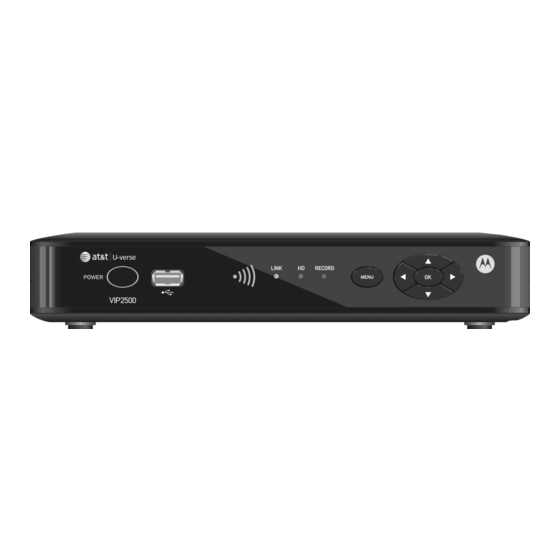
Overview Front Panel The illustration below and the table following it describe the front-panel features, controls and indicator lights. Item Function POWER Turns the U-verse TV receiver on or off If held for ten (10) seconds or longer, restarts the TV receiver Lights green when the TV receiver is on USB 2.0 connector SIGNAL... -
Page 9: Vip2500 Rear Panel
Overview Rear Panel The VIP2500 rear panel features are described in the following table. Item Function RESET Push-pin switch; use only as directed by your service provider. NETWORK Ethernet 10/100Base-T RJ-45 port RCA component video outputs to an HDTV VIDEO OUT RCA standard-definition composite video output to a TV, VCR, or other device Left and right RCA stereo audio (analog) outputs... -
Page 10: Wireless Connection
Wireless Connection As shown in the sketch below, programs and services for the VIP2500 are transmitted wirelessly over the air from a VAP2500 Access Point. The access point, in turn, is connected to your home network gateway device. 802.11n Wireless Link Home Gateway VAP2500 VIP2500... -
Page 11: Connecting Your Tv Receiver
Connecting Your TV Receiver This section describes alternative methods for connecting the VIP2500 to your home entertainment system. Instructions and diagrams are included for connections to: • High-Definition TV (HDTV) • Home Theater Receiver–Audio • Stereo TV Before you move or change components on your entertainment system, always disconnect power from the TV receiver. -
Page 12: Common Cabling Examples
Connecting Your TV Receiver Connector Description To connect a Standard Definition TV, use the composite VIDEO Composite Video OUT connector. VIDEO Composite video provides a Standard-Definition analog video signal. If your equipment supports an optical S/PDIF audio connection, use the OPTICAL connection. Otherwise, use the baseband AUDIO L and R connections. -
Page 13: Connecting To An Hdtv - Video Only
Connecting to an HDTV – Video Only Component video HDMI connection connection Either / or Sample HDTV Component Video Input HDMI CABLE/ ANTENNA IN • If your HDTV has an HDMI input, connect an HDMI cable to the HDMI connector as shown. -
Page 14: Connecting To An Hdtv - Audio Only
Connecting to an HDTV – Audio Only Baseband audio Optical S/PDIF connection connection Either / or INPUT AUDIO LEFT AUDIO RIGHT CABLE/ ANTENNA IN OPTICAL SPDIF Sample HDTV audio inputs If your equipment supports it, use the OPTICAL S/PDIF output. Otherwise, use the AUDIO OUT L and R connectors. -
Page 15: Connecting Audio To A Home Theater Receiver
Connecting Audio to a Home Theater Receiver Baseband audio Optical S/PDIF connection connection Either / or AUDIO VIDEO DIGITAL INPUT VIDEO S-VIDEO COAX OPTICAL CABLE/TV VIDEO 2 TV/MONITOR SPEAKER OUTPUT CONNECTORS VIDEO S-VIDEO Sample home theater receiver If your home theater receiver supports it, use the OPTICAL S/PDIF output. Otherwise, use the AUDIO OUT L and R connectors. -
Page 16: Connecting To A Stereo Tv
Connecting to a Stereo TV Composite video Baseband audio connection connection Sample stereoTV INPUT S-VIDEO VIDEO AUDIO LEFT CABLE/ ANTENNA IN AUDIO RIGHT This video connection method does not support HD video. For more information, see “Connecting an HDTV – Video Only. ” VIP2500 Series High-Definition U-verse Receiver Installation Manual... -
Page 17: Troubleshooting
Troubleshooting Before calling your service provider, review this troubleshooting guide. If the suggestions do not help you quickly solve a problem, contact your service provider. Problem Possible Solution The TV receiver will Verify that the power adapter is connected to the TV receiver not power on. - Page 18 Troubleshooting Problem Possible Solution There is no audio Verify that the Mute button on the remote control has not been when viewing TV pressed. Press Mute on the remote control to restore sound. channels. If the TV receiver audio output is connected to the TV, verify that the Mute button on the TV has not been pressed.
- Page 19 According to 47 CFR, Parts 2 and 15 for Class B Personal Computers and Peripherals; and/or CPU Boards and Power Supplies used with Class B Personal Computers, Motorola Mobility, LLC, 6450 Sequence Drive, San Diego, CA 92121, 1 800 225 9446, declares under sole responsibility that the product identifies with 47 CFR Part 2 and 15 of the FCC Rules as a Class B digital device.
- Page 20 Le guide d’utilisation des dispositifs pour réseaux locaux doit inclure des instructions précises sur les restrictions susmentionnées, notamment : Les dispositifs fonctionnant dans la bande 5 150-5 250 MHz sont réservés uniquement pour une utilisation à l’intérieur afin de réduire les risques de brouillage préjudiciable aux systèmes de satellites mobiles utilisant les mêmes canaux;...
- Page 21 Software provided by third parties may be subject to separate end user license agreements from the manufacturers of such Software. The Software is never sold. Motorola licenses the Software to the original customer and to any subsequent licensee for personal use only on the terms of this License. Motorola and its third party licensors retain the ownership of the Software.
- Page 22 Motorola Mobility, LLC. Motorola reserves the right to revise this publication and to make changes in content from time to time without obligation on the part of Motorola to provide notification of such revision or change. Motorola provides this guide without warranty of any kind, either implied or expressed, including but not limited to the implied warranties of merchantability and fitness for a particular purpose.
- Page 23 Notes VIP2500 Series High-Definition U-verse Receiver Installation Manual...
- Page 24 Visit our website at: www.motorola.com 588574-001-1 07/12...