LG BUSYLJR Owner's Manual
Hide thumbs
Also See for BUSYLJR:
- Service manual (122 pages) ,
- Safety and reference (45 pages) ,
- Owner's manual (37 pages)

Related Manuals for LG BUSYLJR


Summary of Contents for LG BUSYLJR
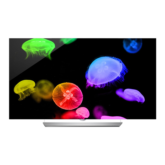
- Page 1 OWNER’S MANUAL Please read this manual carefully before operating your set and retain it for future reference. 55EG9600 55EF9500 55EG9200 65EG9600 65EF9500 *MFL68680222* www.lg.com P/NO : MFL68680222 (1506-REV02)
- Page 2 IMPORTANT SAFETY INSTRUCTIONS IMPORTANT SAFETY INSTRUCTIONS Always comply with the following precautions to avoid dangerous situations and ensure peak performance of your product. Read these instructions. WARNING/CAUTION Keep these instructions. RISK OF ELECTRIC SHOCK Heed all warnings. DO NOT OPEN Follow all instructions.
- Page 3 IMPORTANT SAFETY INSTRUCTIONS Protect the power cord from being walked on not touch the end of the power cord while it is or pinched particularly at plugs, convenience plugged in. receptacles, and the point where they exit Keep the packing anti-moisture material or from the apparatus.
- Page 4 Do not attempt to modify this product in any way cables on the back of the TV. without written authorization from LG Electronics. Do not allow an impact shock or any objects to fall Unauthorized modification could void the user’s into the product, and do not drop anything onto authority to operate this product.
-
Page 5: Fcc Notice
IMPORTANT SAFETY INSTRUCTIONS dots are deactivated pixels and do not affect the Avoid displaying a fixed image on the TV screen performance and reliability of the TV. for a long period of time (2 or more hours for LCD, Generated Sound 1 or more hours for the Plasma TV) to prevent Cracking noise A cracking noise that occurs when image burn. -
Page 6: Industry Canada Statement
20 cm (7.8 inches) between the in some countries. LG Electronics evaluates products’ antenna and your body. recyclability at the design step using LG’s recyclability evaluation tool, with the goal of improving recyclability NOTE: THE MANUFACTURER IS NOT RESPONSIBLE where practicable. -
Page 7: Viewing 3D Imaging
Cautions when using the 3D glasses Symptoms which require discontinuation or refraining from watching 3D contents Make sure to use LG 3D glasses. Otherwise, you may not be able to view 3D videos properly. Do not watch 3D contents when you feel... -
Page 8: Licenses
In addition to the source code, all referred license terms, warranty disclaimers and copyright notices are available for download. LG Electronics will also provide open source code to you on CD-ROM for a charge covering the cost of performing such distribution (such as the cost of media, shipping, and handling) upon email request to [email protected]... -
Page 9: Table Of Contents
- Digital Optical Audio Connection - IC Radiation Exposure Statement Connecting Headphones - Note to Cable/TV Installer Connecting a USB Drive - LG Recycling Policy Viewing 3D Imaging MAGIC REMOTE FUNCTIONS Registering Magic Remote LICENSES How to Use Magic Remote... -
Page 10: Installation Procedure
INSTALLATION PROCEDURE / ASSEMBLING AND PREPARING INSTALLATION PROCEDURE Open the package and make sure all the accessories are included. Attach the stand to the TV set. Connect an external device to the TV set. Make sure the network connection is available. You can use the TV network functions only when the network connection is made. - Page 11 ASSEMBLING AND PREPARING Magic Remote, Owner’s Manual Cable Holder Batteries (AA) (See page 21.) (See page 33.) (For 55EG9600) (For 65EG9600) Cinema 3D Glasses Stand Base Stand Base The number of 3D glasses (See page 16, 17.) (See page 17, 18.) may differ depending upon the model or country.
-
Page 12: Optional Extras
Contact your dealer for buying these items. These devices work only with certain models. The model name or design may be changed manufacturer’s circumstances or policies. AN-MR6** AG-F*** AN-VC550 Magic Remote Cinema 3D Glasses Smart Camera AG-F***DP LG Audio Device Dual Play Glasses... -
Page 13: Parts And Buttons
Intelligent sensor - Adjusts the image quality and brightness based on the surrounding environment. Joystick button is located below the screen of TV. NOTE You can set the LG Logo Light to be on or off by selecting GENERAL in the main menus. (Depending upon model) -
Page 14: Using The Joystick Button
ASSEMBLING AND PREPARING Using the Joystick button You can operate the TV by pressing the button or moving the joystick left, right, up, or down. Basic functions When the TV is turned off, place your finger on the joystick button, Power On press it once, and release it. -
Page 15: Lifting And Moving The Tv
ASSEMBLING AND PREPARING Lifting and Moving the TV Use at least two people to move a large TV. When transporting the TV by hand, hold the TV as shown in the following illustration. When moving or lifting the TV, read the following to prevent the TV from being scratched or damaged and for safe transportation regardless of its type and size. -
Page 16: Setting Up The Tv
ASSEMBLING AND PREPARING Setting Up the TV You can mount your TV to a wall or attach the stand if you wish to place the TV on an entertainment center or other furniture. Attaching the Stand If you are not mounting the TV to a wall, use the following instructions to attach the stand. CAUTION Make sure that the screws are fastened tightly. - Page 17 ASSEMBLING AND PREPARING (For 65EG9600) Packing Brace Stand Cover CAUTION When assembling the stand, lay the packing brace on a table or product box and then 5 EA place the TV with its screen facing down M4 x L20 on the packing brace. Be sure to protect the screen from scratches.
- Page 18 ASSEMBLING AND PREPARING (For 55EF9500) Stand Cover 8 EA M4 x L20 CAUTION Do not place the TV without the stand attached into its upright position. The protruding Joystick Button may be damaged. Use a flat tool to remove the stand cover. Cover Holder Stand Base Insert the protruding parts of the stand cover...
- Page 19 ASSEMBLING AND PREPARING (For 65EF9500) Stand Cover 5 EA M4 x L14 CAUTION Do not place the TV without the stand attached into its upright position. The protruding Joystick Button may be damaged. Use a flat tool to remove the stand cover. Cover Holder Stand Base Insert the protruding parts of the stand cover...
-
Page 20: Mounting On A Table
ASSEMBLING AND PREPARING Mounting on a Table (Image shown may differ from your TV.) Lift and tilt the TV into its upright position on a table. 10 cm - Leave a 10 cm (4 inches) (minimum) space from the wall for proper ventilation. 1 0 c m 1 0 c m 1 0 c m... -
Page 21: Tidying Cables
ASSEMBLING AND PREPARING Tidying Cables Securing the TV to a wall (optional) (Depending upon model) Gather and bind the cables with the cable holder. Insert and tighten the eye-bolts, or TV brackets and bolts on the back of the TV. - If there are bolts inserted at the eye-bolts position, remove the bolts first. -
Page 22: Mounting On A Wall
ASSEMBLING AND PREPARING Mounting on a Wall An optional wall mount can be used with your LG Television. Consult with your local dealer for a wall mount used by your TV model. Carefully attach the Wall mount bracket (optional) wall mount bracket at the rear of the TV. Install the... -
Page 23: Making Connections
MAKING CONNECTIONS MAKING CONNECTIONS You can connect various external devices to the TV. Supported external devices are: HD receivers, DVD players, VCRs, audio systems, USB storage devices, PC, gaming devices, and other external devices. For more information on external device’s connection, refer to the manual provided with each device. NOTE If you record a TV program on a DVD recorder or VCR, make sure to connect the TV signal input cable to the TV through a DVD recorder or VCR. -
Page 24: Connecting To A Hd Receiver, Dvd Player, Or Vcr
MAKING CONNECTIONS Connecting to a HD receiver, DVD Player, or VCR Connect a HD receiver, DVD Player, or VCR to the TV and select an appropriate input mode. NOTE HDMI specifications may be different for each input port, so make sure to check the device specifications before connecting. -
Page 25: Dvi To Hdmi Connection
MAKING CONNECTIONS DVI to HDMI Connection Transmits the digital video signal from an external device to the TV. Connect the external device and the TV with the DVI-HDMI cable as shown in the following illustration. To transmit an audio signal, connect an audio cable. -
Page 26: Component Connection
MAKING CONNECTIONS Component Connection Transmits analog video and audio signals from an external device to the TV. Connect the external device and the TV with a component cable as shown in the following illustration. NOTE If cables are installed incorrectly, it could cause the image to display in black and white or with distorted color. Check to ensure the cables are matched with the corresponding color connection. -
Page 27: Composite Connection
MAKING CONNECTIONS Composite Connection Transmits analog video and audio signals from an external device to the TV. Connect the external device and the TV with the composite cable as shown in the following illustration. NOTE If you have a mono VCR, connect the audio cable from the VCR to the AUDIO L/MONO jack of the TV. Check to ensure the cables are matched with the corresponding color connection. -
Page 28: Connecting To A Pc
MAKING CONNECTIONS Connecting to a PC NOTE Use an HDMI connection for the best image quality. Depending upon the graphics card, DOS mode video may not work if a HDMI to DVI Cable is in use. In PC mode, there may be noise associated with the resolution, vertical pattern, contrast or brightness. If noise is present, change the PC output to another resolution, change the refresh rate to another rate or adjust the brightness and contrast on the PICTURE menu until the picture is clear. -
Page 29: Hdmi Connection Or Dvi To Hdmi Connection
MAKING CONNECTIONS HDMI Connection or DVI to HDMI Connection Choose method A or B to make connection. Method A HDMI Connection (*Not Provided) HDMI Method B DVI to HDMI Connection (*Not Provided) (*Not Provided) AUDIO OUT DVI OUT... -
Page 30: Connecting To An Audio System
MAKING CONNECTIONS Connecting to an Audio System You may use an optional external audio system instead of the built-in speaker. Digital Optical Audio Connection Transmits a digital audio signal from the TV to an external device. Connect the external device and the TV with the optical audio cable as shown in the following illustration. -
Page 31: Connecting Headphones
MAKING CONNECTIONS Connecting Headphones (For EG9600, EF9500 series) Listening to sound with headphones. NOTE Do not use headsets (earphones) at high volume or for a long time. It may cause damage to your hearing. AUDIO menu options are disabled when headphones are connected. When changing AV MODE with a headphone connected, the change is applied to video but not to audio. -
Page 32: Connecting A Usb Drive
MAKING CONNECTIONS Connecting a USB Drive Connect a USB storage device such as a USB flash thumbdrive, external hard drive, or a USB memory card reader to the TV and access the SmartShare menu to use various multimedia files. NOTE Some USB Hubs may not work. -
Page 33: Magic Remote Functions
MAGIC REMOTE FUNCTIONS MAGIC REMOTE FUNCTIONS Magic remote control battery is low. Change the battery When the message . is displayed, replace the battery. To install batteries, open the battery cover, replace batteries (1.5 V AA) matching ends to the label inside the compartment, and close the battery cover. -
Page 34: Registering Magic Remote
MAGIC REMOTE FUNCTIONS / USING THE USER GUIDE Registering Magic Remote Precautions to Take Use the remote control within the specified range (within 10 m or 32.8 ft.) You may How to register the Magic Remote experience communication failures when using the device outside the coverage area or if there are obstacles within the coverage area. -
Page 35: Specifications
SPECIFICATIONS SPECIFICATIONS Product specifications may be changed without prior notice due to upgrade of product functions. Power requirement AC 120 V ~ 50 / 60 Hz Television System NTSC-M, ATSC, 64 & 256 QAM Program Coverage VHF 2-13, UHF 14-69, CATV 1-135, DTV 2-69, CADTV 1-135 External Antenna Impedance 75 Ω... - Page 36 SPECIFICATIONS Wireless module (LGSBW41) Specifications Wireless Lan Bluetooth Standard Standard IEEE 802.11a/b/g/n Bluetooth Version 4.0 2400 to 2483.5 MHz Frequency Range 5150 to 5250 MHz Frequency Range 2400 to 2483.5 MHz 5725 to 5850 MHz 802.11a: 11.5 dBm 802.11b: 11 dBm Output Powe r Output Power 802.11g: 10.5 dBm...
-
Page 37: Maintenance
MAINTENANCE / TROUBLESHOOTING MAINTENANCE Cleaning Your TV Clean your TV regularly to keep it at peak performance and to extend the product lifespan. CAUTION Make sure to turn the power off and disconnect the power cord and all other cables first. When the TV is left unattended or unused for a long time, disconnect the power cord from the wall outlet to prevent possible damage from lightning or power surges. - Page 39 CHILD SAFETY: PROPER TELEVISION PLACEMENT MATTERS THE CONSUMER ELECTRONICS INDUSTRY CARES • Manufacturers, retailers and the rest of the consumer electronics industry are committed to making home entertainment safe and enjoyable. • As you enjoy your television, please note that all televisions – new and old- must be supported on proper stands or installed according to the manufacturer’s recommendations.
- Page 40 LG Customer Information Center Declaration of Conformity For inquires or comments, visit www.lg.com or call; Trade Name 1-800-243-0000 USA, Consumer User Model 55EG9600-UA, 65EG9600-UA 1-888-865-3026 USA, Commercial User 55EF9500-UA, 65EF9500-UA 1-888-542-2623 CANADA 55EG9200-UA Register your product online! Responsible LG Electronics Inc.
- Page 41 OWNER’S MANUAL EXTERNAL CONTROL DEVICE SETUP Please read this manual carefully before operating the set and retain it for future reference. www.lg.com...
-
Page 42: Note
KEY CODES KEY CODES • This feature is not available for all models. Code Code Function Note Function Note (Hexa) (Hexa) CH +, PR + R/C Button List R/C Button CH -, PR - R/C Button Exit R/C Button Volume + R/C Button PIP(AD) R/C Button... -
Page 43: Image Shown May Differ From Your Tv
(TV) (PC) • LGTV supports PL2303 chip-based (Vendor ID : 0x0557, Product ID : 0x2008) USB to serial converter RS-232C IN which is not made nor provided by LG. (CONTROL & SERVICE) (PC) (TV) • It can be purchased from computer stores that carry accessories for IT support professionals. - Page 44 EXTERNAL CONTROL DEVICE SETUP (TV) (PC) (TV) (PC) Phone jack Type RS-232C IN • You need to purchase the phone-jack to RS-232 cable required for the connection between the PC and (CONTROL & SERVICE) (PC) (TV) the TV, which is specified in the manual. RS-232C IN (CONTROL &...
- Page 45 EXTERNAL CONTROL DEVICE SETUP Communication Parameters • Baud rate : 9600 bps (UART) • Stop bit : 1 bit • Data length : 8 bits • Communication code : ASCII code • Parity : None • Use a crossed (reverse) cable. Command reference list (Depending on model) DATA...
- Page 46 EXTERNAL CONTROL DEVICE SETUP Transmission / Receiving Protocol Transmission [Command1][Command2][ ][Set ID][ ][Data][Cr] [Command 1] : First command to control the TV. (j, k, m or x) [Command 2] : Second command to control the TV. [Set ID] : You can adjust the [Set ID] to choose desired monitor ID number in option menu. Adjustment range in TV is 1 to 99.
- Page 47 EXTERNAL CONTROL DEVICE SETUP * Commands may work differently depending on model and signal. 01. Power (Command: k a) Ack [d][ ][Set ID][ ][OK/NG][Data][x] ► To control Power *On or Off of the set. * In case of video mute on only, TV will display On Transmission[k][a][ ][Set ID][ ][Data][Cr] Screen Display(OSD).
- Page 48 EXTERNAL CONTROL DEVICE SETUP Data Min : 00 to Max : 64 * (Depending on model) Ack [i][ ][Set ID][ ][OK/NG][Data][x] 14. Bass (Command: k s) 09. Tint (Command: k j) ► To adjust Bass. ► To adjust the screen tint. You can also adjust in the AUDIO menu.
- Page 49 EXTERNAL CONTROL DEVICE SETUP Set ID = All = 00 5th Band 20(decimal) Data 00 & 01 = Channel Data is 10 = 00 0a Acknowledgement [v][ ][Set ID][ ][OK/NG][Data][x] Data 02 = Analog Antenna TV = 00 Result = ma 00 00 0a 00 * It depends on model, and can adjust when sound mode is EQ adjustable value.
- Page 50 EXTERNAL CONTROL DEVICE SETUP Number Data 05 = Digital Antenna TV = 02 - 22 : Antenna TV (DTV) – Don’t Use Physical Total = ma 00 00 00 11 00 01 02 Channel Number - 26 : Cable TV (CADTV) - Don’t Use Physical 2.
- Page 51 11 11 EXTERNAL CONTROL DEVICE SETUP 24. Input select (Command: x b) (Main Picture Input) ► To select input source for main picture. Transmission [x][b][ ][Set ID][ ][Data][Cr] Data X : don’t care 00 : DTV 01 : CADTV 02 : Satellite DTV 10 : ATV Ack [t][ ][Set ID][ ][OK][Data00][Data01][Data02] ISDB-BS (Japan)
- Page 52 EXTERNAL CONTROL DEVICE SETUP 27. Auto Configure (Command: j u) (Depending on model) ► To adjust picture position and minimize image shaking automatically. It works only in RGB (PC) mode. Transmission [j][u][ ][Set ID][ ][Data][Cr] Data 01 : To set Ack [u][ ][Set ID][ ][OK/NG][Data][x]...