Table of Contents
Quick Links
Table of Contents

Related Manuals for Asus RS720A-E9-RS24-E


Summary of Contents for Asus RS720A-E9-RS24-E
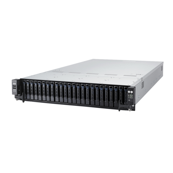
- Page 1 RS720A-E9-RS24-E 2U Rackmount Server User Guide...
- Page 2 ASUSTeK COMPUTER INC. (“ASUS”). ASUS provides this manual “as is” without warranty of any kind, either express or implied, including but not limited to the implied warranties or conditions of merchantability or fitness for a particular purpose. In no...
-
Page 3: Table Of Contents
Installing an expansion card to riser card bracket 3 ....2-18 2.5.4 Installing an expansion card to riser card bracket 4 ....2-20 2.5.5 Replacing the ASUS PIKE II card ..........2-22 2.5.6 Configuring an expansion card ..........2-25 2.5.7 Installing Mezzanine cards ............ - Page 4 Internal LEDs (revised motherboard) ............. 4-31 Internal connectors (revised motherboard) ........... 4-34 Chapter 5: BIOS Setup Managing and updating your BIOS ............5-2 5.1.1 ASUS CrashFree BIOS 3 utility........... 5-2 5.1.2 ASUS EZ Flash Utility ..............5-3 5.1.3 BUPDATER utility ............... 5-4 BIOS setup program ..................
- Page 5 Contents Main menu ....................5-9 5.3.1 System Date [Day xx/xx/xxxx] ............. 5-9 5.3.2 System Time [xx:xx:xx] ............... 5-9 Advanced menu ..................5-10 5.4.1 Trusted Computing..............5-11 5.4.2 PSP Firmware Versions ............5-11 5.4.3 APM ..................5-12 5.4.4 Smart Settings................5-13 5.4.5 NCT6793D Super IO Configuration ..........
- Page 6 I350-AM2 Gigabit Adapters driver ......6-6 VGA driver installation ................6-8 Appendix KNPP-D32 block diagram ..................A-2 Notices ........................A-3 Canadian Department of Communications Statement .........A-4 REACH ....................A-4 ASUS Recycling/Takeback Services ............A-4 Australia statement notice ................A-4 ASUS contact information ..................A-5...
-
Page 7: Safety Information
Safety information Electrical Safety • Before installing or removing signal cables, ensure that the power cables for the system unit and all attached devices are unplugged. • To prevent electrical shock hazard, disconnect the power cable from the electrical outlet before relocating the system. -
Page 8: About This Guide
About this guide Audience This user guide is intended for system integrators, and experienced users with at least basic knowledge of configuring a server. Contents This guide contains the following parts: Chapter 1: Product Introduction This chapter describes the general features of the server, including sections on front panel and rear panel specifications. - Page 9 Refer to the following sources for additional information, and for product and software updates. ASUS Control Center (ACC) user guide This manual tells how to set up and use the proprietary ASUS server management utility. Visit asuscontrolcenter.asus.com for more information. ASUS websites The ASUS websites worldwide provide updated information for all ASUS hardware and software products.
-
Page 11: Chapter 1: Product Introduction
Chapter 1: Product Introduction Product Introduction This chapter describes the general features of the chassis kit. It includes sections on front panel and rear panel specifications. -
Page 12: System Package Contents
1 x SAS/SATA back panel Component 24 x Hot-swap 2.5-inch Storage Device Trays 1 x Front Panel Board 4 x System Fans 1 x RS720A-E9-RS24-E Support CD 1 x Bag of Screws Accessories 2 x CPU Heatsink 2 x AC Power Cable... -
Page 13: System Specifications
System specifications The ASUS RS720A-E9-RS24-E features the ASUS KNPP-D32 server board. The server supports AMD EPYC™ 7000 Series processors plus other latest technologies through the chipsets onboard. Model Name RS720A-E9-RS24-E Motherboard KNPP-D32 AMD EPYC™ 7000 Series Processor Support xGMI (External Global Memory Interface Link) - Page 14 * LAN 3-4 for Mezzanine card use Out of Band Remote On-Board ASMB9-iKVM for KVM-over-IP Management Hardware Solution Software ASUS Control Center (Classic) OS Support Please find the latest OS support from http://www.asus.com/ (continued on the next page) Chapter 1: Product Introduction...
- Page 15 Rating: 100-127/200-240Vac, 10A/8A (x2), 50/60Hz Class I (240Vdc, 6A only for China) Operating temperature: 10°C ~ 35°C Environment Non operating temperature: -40°C ~ 60°C Non operating humidity: 20% ~ 90% (Non condensing) * Specifications are subject to change without notice. ASUS RS720A-E9-RS24-E...
-
Page 16: Front Panel Features
Power button VGA port • * This port is for ASUS ASMB9-iKVM only. • The Q-Code LED provides the most probable cause of an error code as a starting point for troubleshooting. The actual cause may vary from case to case. -
Page 17: Internal Features
Internal features The barebone server includes the basic components as shown. Redundant Power supply ASUS KNPP-D32 Server Board System fans SATA/SAS back panel 24 x 2.5” storage device trays Front panel (hidden) Asset tag (hidden) The barebone server does not include a floppy disk drive. Connect a USB floppy disk drive to any of the USB ports on the front or rear panel if you need to use a floppy disk. -
Page 18: Led Information
LED information 1.7.1 Front panel LEDs Location button Power button LAN1 LED Message LED LAN2 LED Storage device LAN4 LED access LED LAN3 LED RESET button Icon Display status Description Power LED System power ON No activity Storage device access LED Blinking Read/write data into the storage device System is normal;... -
Page 19: Storage Device Status Led
Read/write data from/into the SATA/SAS storage device 1.7.3 LAN (RJ-45) LEDs ACT/LINK LED SPEED LED ACT/LINK LED SPEED LED Status Description Status Description No link 10 Mbps connection GREEN Linked ORANGE 100 Mbps connection BLINKING Data activity GREEN 1 Gbps connection ASUS RS720A-E9-RS24-E... -
Page 20: Q-Code Table
1.7.4 Q-Code table Action PHASE POST CODE TYPE DESCRIPTION 0x01 Progress First post code 0x02 Progress Load BSP microcode 0x03 Progress Perform early platform Initialization SEC Start up Security Phase 0x04 Progress Set cache as ram for PEI phase 0x05 Progress Establish Stack 0x06... - Page 21 Error in checksum from wrapped Knoll/Prom keys 0x9C Error Knoll returned an invalid response to a command 0x9D Error Bootloader failed in Knoll Send Command function 0x9E Error No Knoll device found by verifying MAC (continued on the next page) ASUS RS720A-E9-RS24-E 1-11...
- Page 22 Action PHASE POST CODE TYPE DESCRIPTION 0xA0 Progress Bootloader successfully entered C Main 0xA1 Progress Master initialized C2P / slave waited for master to init C2P 0xA2 Progress HMAC key successfully derived 0xA3 Progress Master got Boot Mode and sent boot mode to all slaves 0xA4 Progress SpiRom successfully initialized...
- Page 23 BIOS Setup Utility password verify 0xA9 Progress BIOS Setup Utility start 0xAB Progress BIOS Setup Utility input wait 0xAD Progress Ready to boot event 0xAE Progress Legacy boot event 0xAA Progress APIC mode Operating system phase 0xAC Progress PIC mode ASUS RS720A-E9-RS24-E 1-13...
- Page 24 1-14 Chapter 1: Product Introduction...
-
Page 25: Chapter 2: Hardware Information
Chapter 2: Hardware Information Hardware Information This chapter lists the hardware setup procedures that you have to perform when installing or removing system components. -
Page 26: Chassis Cover
Chassis cover Removing the rear cover To remove the rear cover: Remove the six (6) screws on the rear cover with a Phillips screwdriver. Push and hold the cover buttons down, then slide the rear cover towards the rear to disengage it from the chassis. -
Page 27: Central Processing Unit (Cpu)
Authorization (RMA) requests only if the motherboard comes with the cap on the Socket SP3. • The product warranty does not cover damage to the socket contacts resulting from incorrect CPU installation/removal, or misplacement/loss/incorrect removal of the PnP cap. 2.2.1 Installing the CPU and heatsink To install a CPU: Remove the rear cover. For more information, see the section Chassis cover. Remove the screws then remove the air ducts. ASUS RS720A-E9-RS24-E... - Page 28 Loosen each screw one by one in the sequence shown on the socket to open the load plate. Slightly lift open the rail frame. Load plate Rail frame External cap Slide the external cap out of the rail frame. External cap Rail frame PnP cap Chapter 2: Hardware Information...
- Page 29 Close the load plate just enough to let it sit on top of the CPU, then secure each screw one by one in the sequence shown on the socket to completely secure the load plate. The load plate screws are T20 models. A torque value of 12 inch-lbf is recommended. ASUS RS720A-E9-RS24-E...
- Page 30 Twist each of the four screws with a Phillips screwdriver just enough to attach the heatsink to the motherboard. When the four screws are attached, tighten them one by one in a diagonal sequence to completely secure the heatsink. Reinstall the air ducts then secure the air ducts with the screws removed in step 2. Chapter 2: Hardware Information...
-
Page 31: System Memory
System memory 2.3.1 Overview The motherboard comes with 32 Double Data Rate 4 (DDR4) Dual Inline Memory Modules (DIMM) sockets. The figure illustrates the location of the DDR4 DIMM sockets: ASUS RS720A-E9-RS24-E... -
Page 32: Memory Configurations
You may install 8GB, 16GB, and 32GB RDIMMs; 32GB, 64GB, and 128GB LRDIMMs into the DIMM sockets. If you are not sure on which slots to install the DIMMS, you can use the recommended memory configuration in this section for reference. • Refer to ASUS Server AVL for the updated list of compatible DIMMs. • Always install DIMMs with the same CAS latency. For optimum compatibility, it is recommended that you obtain memory modules from the same vendor. -
Page 33: Installing A Dimm On A Single Clip Dimm Socket
Always insert the DIMM into the socket vertically to prevent DIMM notch damage. 2.3.4 Removing a DIMM from a single clip DIMM socket Press the retaining clip outward to unlock the DIMM. Remove the DIMM from the socket. Support the DIMM lightly with your fingers when pressing the retaining clips. The DIMM might get damaged when it flips out with extra force. ASUS RS720A-E9-RS24-E... -
Page 34: Storage Devices
The system supports twenty-four (24) 2.5” hot-swap SATA/SAS storage devices. The storage device installed on the storage device tray connects to the motherboard SATA/SAS ports via the SATA/SAS backplane (SAS storage devices require an optional ASUS PIKE II card). To install a 2.5” hot-swap SATA/SAS storage device: Switch the secure lock upward then pull the tray lever outward. The storage device tray ejects slightly after you pull out the lever. - Page 35 Push the tray lever until it clicks and secures the storage device tray in place. Repeat steps 1 to 7 to install the other SATA/SAS storage devices. ASUS RS720A-E9-RS24-E 2-11...
-
Page 36: Expansion Slot
Operation mode Slot 1 Slot 2 Slot 3 x8 (ASUS PIKE II card by default) x8 (ASUS PIKE II card by default) Riser card bracket 2 Riser card bracket 2 supports PCIe Gen3 slots 4-5 top to bottom. Slot 4 can be auto-switch to x16 mode when x16 card is populated whereas slot 5 will be disabled. - Page 37 Slot 7 Riser card bracket 4 Riser card bracket 4 supports PCIe Gen3 slot 8. PCIe slot Operation mode Slot 8 OCP Mezzanine slot OCP Mezzanine slot supports PCIe Gen3 x16. PCIe slot Operation mode OCP Mezzanine ASUS RS720A-E9-RS24-E 2-13...
-
Page 38: Installing An Expansion Card To Riser Card Bracket 1
2.5.1 Installing an expansion card to riser card bracket 1 The pre-installed riser card bracket 1 on the PCIE1 slot supports Full-Height (FH) and Half- Length (HL) PCIE x16 expansion cards. To install an expansion card to the riser card bracket 1: Remove the screw that secures the riser card bracket 1 to the chassis. - Page 39 Install the riser card bracket 1 and the PCIE expansion card assembly into the PCIE1 slot on the motherboard. Ensure that the golden connectors of the riser card bracket 1 is firmly seated in place. Secure the riser card bracket 1 to the chassis with the screw removed in step 1. ASUS RS720A-E9-RS24-E 2-15...
-
Page 40: Installing An Expansion Card To Riser Card Bracket 2
2.5.2 Installing an expansion card to riser card bracket 2 To install an expansion card on the riser card bracket 2: Remove the two screws that secure the riser card bracket 2 to the chassis. Remove the screw that secures Riser card bracket 2 the riser card bracket 2 to the motherboard. - Page 41 Secure the riser card bracket 2 to the motherboard with the screw removed in step 2. Secure the riser card bracket 2 to the chassis with the screws removed in step 1. ASUS RS720A-E9-RS24-E 2-17...
-
Page 42: Installing An Expansion Card To Riser Card Bracket 3
2.5.3 Installing an expansion card to riser card bracket 3 To install an expansion card on the riser card bracket 3: Remove the two screws that secure the riser card bracket 3 to the chassis. Firmly hold the riser card bracket 3, then pull it up to detach it from the PCIE4 slot on the motherboard. - Page 43 Install the riser card bracket 3 and the PCIE expansion card assembly into the PCIE4 slot on the motherboard. Ensure that the golden connectors of the riser card bracket 3 is firmly seated in place. Secure the riser card bracket 3 to the chassis with the screws removed in step 1. ASUS RS720A-E9-RS24-E 2-19...
-
Page 44: Installing An Expansion Card To Riser Card Bracket 4
2.5.4 Installing an expansion card to riser card bracket 4 To install an expansion card to the riser card bracket 4: Remove the riser card bracket 1 and riser card bracket 2. For more information, refer to section 2.5.1 Installing an expansion card to riser card bracket 1 and 2.5.2 Installing an expansion card to riser card bracket 2. - Page 45 Riser card bracket 4 Move the metal lock downward to secure the riser card bracket 4 and the PCIE expansion card assembly to the chassis. Secure the metal lock to the chassis with the screw removed in step 2. ASUS RS720A-E9-RS24-E 2-21...
-
Page 46: Replacing The Asus Pike Ii Card
2.5.5 Replacing the ASUS PIKE II card To replace the pre-installed ASUS PIKE II card on the riser card bracket 1: Remove the screw that secures the riser card bracket 1 to the chassis. Firmly hold the riser card bracket 1, then pull it up to detach it from the PCIE1 slot on the motherboard. - Page 47 Remove the default cable from the ASUS PIKE II card. Prepare the replacement ASUS PIKE II card. Reconnect the default cable to the replacement ASUS PIKE II card. Install the replacement ASUS PIKE II card into the riser card bracket 1 (A), then secure it with the screw (B). ASUS RS720A-E9-RS24-E 2-23...
- Page 48 Install the riser card bracket 1 and the ASUS PIKE II card assembly into the PCIE1 slot on the motherboard. Ensure that the golden connectors of the riser card bracket 1 is firmly seated in place. Secure the riser card bracket 1 to the chassis with the screw removed in step 1. Chapter 2: Hardware Information 2-24...
-
Page 49: Configuring An Expansion Card
ACPI Mode when used IRQ Holder for PCI Steering IRQ Holder for PCI Steering PS/2 Compatible Mouse Port Numeric Data Processor Primary IDE Channel Secondary IDE Channel * These IRQs are usually available for ISA or PCI devices. ASUS RS720A-E9-RS24-E 2-25... -
Page 50: Installing Mezzanine Cards
2.5.7 Installing Mezzanine cards To install a Mezzanine card: Locate the Mezzanine card connector on your motherboard. Remove the riser card bracket 1. For more information, refer to section 2.5.1 Installing an expansion card to riser card bracket 1. Remove the screw from the metal cover (A), then remove the metal cover (B) from chassis. - Page 51 Ensure that the stand screws on the motherboard is aligned and matched to the screw holes of the Mezzanine card. Ports OCP connector Mounting hole Stand screw Stand screw Secure the Mezzanine card with four bundled screws. ASUS RS720A-E9-RS24-E 2-27...
- Page 52 Reinstall the metal cover (A) and secure it with the screw (B). Install the riser card bracket 1 into the PCIE connector on the motherboard. For more information, refer to section 2.5.1 Installing an expansion card to riser card bracket 1. Chapter 2: Hardware Information 2-28...
-
Page 53: Installing M.2 (Ngff) Cards
Locate the M.2 (NGFF) connectors on your motherboard. Top screw Stand screw Remove the top screw and the stand from the motherboard. Select an appropriate screw hole on the motherboard for your M.2 card, then secure the stand to the motherboard. ASUS RS720A-E9-RS24-E 2-29... - Page 54 Prepare the M.2 card. Align and insert the M.2 card into the M.2 connector on the motherboard. Ensure that the golden connector of the M.2 card is inserted firmly in place and that the screw hole on the M.2 card matches the stand screw on the motherboard. Secure the M.2 card with the top screw.
-
Page 55: Cable Connections
8-pin BPPWR2 power connector (from power supply to backplane) Auxiliary panel 1 connector (from motherboard to front I/O board) System fan connectors (from motherboard FAN1, 3, 5, 7 to system fans) Panel connector (from motherboard to front I/O board) ASUS RS720A-E9-RS24-E 2-31... -
Page 56: Sata/Sas Backplane Cabling
SATA/SAS backplane cabling Backplane Connects a 8-pin plug Connects to expander board from motherboard Connects to SATA/SAS storage devices Expander board Connects to backplane Connects the data cable from the ASUS PIKE II card Chapter 2: Hardware Information 2-32... -
Page 57: Removable/Optional Components
(C). Install the fan to the fan cage. The fan can only be installed in one direction. If the fan cannot be installed, turn it around and try again. ASUS RS720A-E9-RS24-E 2-33... -
Page 58: Redundant Power Supply Module
2.8.2 Redundant power supply module To replace a failed redundant power supply module: Lift up the power supply module lever. Hold the power supply module lever and press the PSU latch. Pull the power supply module out of the system chassis. PSU latch Module lever Insert the replacement power supply module into the chassis then push it... -
Page 59: Chapter 3: Installation Options
Chapter 3: Installation Options Installation Options This chapter describes how to install the optional components and devices into the barebone server. -
Page 60: Tool-Less Friction Rail Kit
Tool-less Friction Rail Kit The tool less design of the rail kit allows you to easily install the rack rails into the server rack without the need for additional tools. The kit also comes with a metal stopping bracket that can be installed to provide additional support and stability to the server. -
Page 61: Installing The Tool-Less Rack Rail
Select a desired space and place the appropriate rack rail (left and right) on opposite positions on the rack. A 1U space consists of three square mounting holes with two thin lips on the top and the bottom. ASUS RS720A-E9-RS24-E... - Page 62 Secure the rail components to the rail using the bundled screws. Press the spring lock (A) then insert the studs into the selected square mounting holes on the rack post. Press the spring lock on the other end of rail then insert the stud into the mounting hole on the rack post. Extend the rack rail, if necessary.
-
Page 63: Rail Kit Dimensions
Rail kit dimensions 43.6mm 900mm 43.6mm 589mm ASUS RS720A-E9-RS24-E... - Page 64 Chapter 3: Installation Options...
-
Page 65: Chapter 4: Motherboard Information
Chapter 4: Motherboard Information Motherboard Information This chapter includes the motherboard layout and brief descriptions of the jumpers and internal connectors. -
Page 66: Motherboard Layout
Motherboard layout Chapter 4: Motherboard Information... - Page 67 Storage device activity LED connector (4-pin HDLED1) 4-13 M.2 (NGFF) card connectors (NGFF1-2) 4-20 DMLAN setting (3-pin DM_IP_SEL1) Serial ATA connectors (7-pin SATA1-2) 4-12 Mini-SAS HD connector (ISATA1-2) 4-12 USB 3.0 connectors (OCUUSB1) 4-23 TPM connector (14-1 pin TPM1) 4-15 ASUS RS720A-E9-RS24-E...
-
Page 68: Jumpers
Jumpers Clear RTC RAM (3-pin CLRTC1) This jumper allows you to clear the Real Time Clock (RTC) RAM in CMOS. You can clear the CMOS memory of date, time, and system setup parameters by erasing the CMOS RTC RAM data. The onboard button cell battery powers the RAM data in CMOS, which include system setup information such as system passwords. - Page 69 This jumper allows you to enable or disable the onboard VGA controller. Set to pins 1–2 to activate the VGA feature. LAN controller setting (3-pin LAN_SW1-2) ® These jumpers allow you to enable or disable the onboard Intel I350-AM2 Gigabit LAN1/2 controller. Set to pins 1–2 to activate the Gigabit LAN feature. ASUS RS720A-E9-RS24-E...
- Page 70 Baseboard Management Controller setting (3-pin BMC_EN1) This jumper allows you to enable (default) or disable on-board BMC. Ensure to set this BMC jumper to enabled to avoid system fan control and hardware monitor error. Smart Ride Through (SmaRT) setting (3-pin SMART_PSU1) This jumper allows you to enable or disable the Smart Ride Through (SmaRT) function.
- Page 71 This jumper allows you to select the DMLAN setting. Set to pins 2-3 to force the DMLAN IP to static mode (IP=10.10.10.10, submask=255.255.255.0). LANNCSI setting (3-pin LANNCSI_SEL1) This jumper allows you to enable or disable the LAN NCSI. ASUS RS720A-E9-RS24-E...
- Page 72 MEZZNCSI setting (3-pin MEZZNCSI_SEL1) This jumper allows you to enable or disable the MEZZ NCSI. IPMI SW setting (3-pin IPMI_SW1) This jumper allows you to select which protocol in the GPU sensor to function. Chapter 4: Motherboard Information...
-
Page 73: Internal Leds
This onboard LED lights up when the Location button on the server is pressed or when triggered by a system management software. The Location LED helps visually locate and quickly identify the server in error on a server rack. ASUS RS720A-E9-RS24-E... - Page 74 Storage device activity LED (HDDLED1) This LED is reserved for the storage devices connected to the onboard M.2, or SATA/ SAS add-on card. The read or write activities of any device connected to the onboard M.2, or SATA/SAS add-on card causes the rear panel LED to light up. Message LED (MESLED1) This onboard LED lights up to red when there is a BMC event log is generated.
- Page 75 BMC LED (BMCLED1) The BMC LED lights up to indicate that the on-board BMC is functional. ASUS RS720A-E9-RS24-E 4-11...
-
Page 76: Internal Connectors
Internal connectors Serial ATA connectors (7-pin SATA1-2) These connectors, controlled by AMD integrated SATA controller, are for the Serial ATA signal cables for Serial ATA drives (SATA 1 connector is used for the optical drive by default). If the SATA M.2 (NGFF1) slot is occupied, the SSATA2 slot will be disabled. Mini-SAS HD connector (ISATA1-2) This motherboard comes with mini Serial Attached SCSI (SAS) HD connectors, the storage technology that supports Serial ATA. - Page 77 This LED connector is for the storage add-on card cable connected to the SATA or SAS add-on card. The read or write activities of any device connected to the SATA or SAS add-on card causes the front panel LED to light up. ASUS RS720A-E9-RS24-E 4-13...
- Page 78 USB 2.0 connector (10-1 pin USB67) This connector is for USB 2.0 ports. Connect the USB module cable to the connector, and then install the module to a slot opening at the back of the system chassis. The USB connectors comply with USB 2.0 specification that supports up to 480 Mbps connection speed.
- Page 79 TPM connector (14-1 pin TPM1) This connector supports a Trusted Platform Module (TPM) system, which can securely store keys, digital certificates, passwords, and data. A TPM system also helps enhance network security, protects digital identities, and ensures platform integrity. ASUS RS720A-E9-RS24-E 4-15...
- Page 80 System panel connector (20-1 pin PANEL1) This connector supports several chassis-mounted functions. System power LED (3-pin PLED) This 3-pin connector is for the system power LED. Connect the chassis power LED cable to this connector. The system power LED lights up when you turn on the system power, and blinks when the system is in sleep mode.
- Page 81 This 2-pin connector is for the locator button on the front panel. This button queries the state of the system locator. LAN activity LED and USB port (2-pin LAN3_LED, LAN4_LED, USB ports) These 2-pin connectors are for the Gigabit LAN activity LEDs and USB ports on the front panel. ASUS RS720A-E9-RS24-E 4-17...
- Page 82 Back panel power connectors (8-pin BPPWR1-2) These connectors are for the power supply plugs that connects to the back panel. The power supply plugs are designed to fit these connectors in only one orientation. Find the proper orientation and push down firmly until the connectors completely fit. DO NOT connect VGA cards to these connectors.
- Page 83 When you remove any chassis component, the sensor triggers and sends a high level signal to these leads to record a chassis intrusion event. The default setting is to short the CHASSIS# and the GND pin by a jumper cap to disable the function. ASUS RS720A-E9-RS24-E 4-19...
- Page 84 Mezzanine PCIE card connectors (MEZZPCIE1-2) The MEZZPCIE1-2 connector supports Open Compute Project (OCP) cards. M.2 (NGFF) card connectors (NGFF1-2) These connectors allow you to install M.2 devices. • This connector supports type 2242 / 2260 / 2280 / 22110 devices on both PCI-E and SATA interface.
- Page 85 Memory Card, then reboot the system to access the Memory Card. Some memory cards may not be compatible with your motherboard. Ensure that you use only compatible memory cards to prevent loss of data, damage to your device, or memory card, or both. ASUS RS720A-E9-RS24-E 4-21...
- Page 86 OCP LAN Activity LED connector (4-1 pin OCP_LED1) OCP LAN LED connector supports OCP LAN card Active LED. VPP_I2C1 connector (10-1 pin VPP_I2C1) This connector is used for the Intel VMD function and sensor readings. 4-22 Chapter 4: Motherboard Information...
- Page 87 USB 3.0 including faster data transfer speeds of up to 5 Gbps, faster charging time for USB-chargeable devices, optimized power efficiency, and backward compatibility with USB 2.0. (OCUUSB1 connector is used for the front USB panel by default). The USB port module is purchased separately. ASUS RS720A-E9-RS24-E 4-23...
-
Page 88: Motherboard Layout (Revised Motherboard)
Motherboard layout (revised motherboard) - Page 89 Layout contents Internal connectors / Sockets / Jumpers / LEDs Page Chassis Intrusion (2-pin INTRUSION1) 4-41 USB 2.0 connector (10-1 pin USB67) 4-36 DDR4 DIMM sockets Back panel power connectors (8-pin BPPWR1-2) 4-40 System fan connectors (4-pin FRNT_FAN1-8) 4-37 CPU socket VGA power connectors (8-pin VGAPWR1-3) 4-40 Fan power connectors (FANPWR1-3)
-
Page 90: Jumpers (Revised Motherboard)
Jumpers (revised motherboard) Clear RTC RAM (3-pin CLRTC1) This jumper allows you to clear the Real Time Clock (RTC) RAM in CMOS. You can clear the CMOS memory of date, time, and system setup parameters by erasing the CMOS RTC RAM data. The onboard button cell battery powers the RAM data in CMOS, which include system setup information such as system passwords. - Page 91 VGA controller setting (3-pin VGA_SW1) This jumper allows you to enable or disable the onboard VGA controller. Set to pins 1–2 to activate the VGA feature. LAN controller setting (3-pin LAN_SW1-2) ® These jumpers allow you to enable or disable the onboard Intel I350-AM2 Gigabit LAN1/2 controller.
- Page 92 Baseboard Management Controller setting (3-pin BMC_EN1) This jumper allows you to enable (default) or disable on-board BMC. Ensure to set this BMC jumper to enabled to avoid system fan control and hardware monitor error. Smart Ride Through (SmaRT) setting (3-pin SMART_PSU1) This jumper allows you to enable or disable the Smart Ride Through (SmaRT) function.
- Page 93 DMLAN setting (3-pin DM_IP_SEL1) This jumper allows you to select the DMLAN setting. Set to pins 2-3 to force the DMLAN IP to static mode (IP=10.10.10.10, submask=255.255.255.0). LANNCSI setting (3-pin LANNCSI_SEL1) This jumper allows you to enable or disable the LAN NCSI.
- Page 94 IPMI SW setting (3-pin IPMI_SW1) This jumper allows you to select which protocol in the GPU sensor to function.
-
Page 95: Internal Leds (Revised Motherboard)
Internal LEDs (revised motherboard) Standby Power LED (SBPWR1) The motherboard comes with a standby power LED. The green LED lights up to indicate that the system is ON, in sleep mode, or in soft-off mode. This is a reminder that you should shut down the system and unplug the power cable before removing or plugging in any motherboard component. - Page 96 Storage device activity LED (HDDLED1) This LED is reserved for the storage devices connected to the onboard M.2, or SATA/ SAS add-on card. The read or write activities of any device connected to the onboard M.2, or SATA/SAS add-on card causes the rear panel LED to light up. Message LED (MESLED1) This onboard LED lights up to red when there is a BMC event log is generated.
- Page 97 BMC LED (BMCLED1) The BMC LED lights up to indicate that the on-board BMC is functional.
-
Page 98: Internal Connectors (Revised Motherboard)
Internal connectors (revised motherboard) Serial ATA connectors (7-pin SATA1-4) These connectors, controlled by AMD integrated SATA controller, are for the Serial ATA signal cables for Serial ATA drives (SATA 1 connector is used for the optical drive by default). If the SATA M.2 (NGFF1) slot is occupied, the SSATA2 slot will be disabled. Mini-SAS HD connector (ISATA1-2) This motherboard comes with mini Serial Attached SCSI (SAS) HD connectors, the storage technology that supports Serial ATA. - Page 99 MPCIE_HD connectors (MPCIE_HD1-2) The MPCIE_HD connectors allows you to connect NVME storage device. Storage device activity LED connector (4-pin HDLED1) This LED connector is for the storage add-on card cable connected to the SATA or SAS add-on card. The read or write activities of any device connected to the SATA or SAS add-on card causes the front panel LED to light up.
- Page 100 USB 2.0 connector (10-1 pin USB67) This connector is for USB 2.0 ports. Connect the USB module cable to the connector, and then install the module to a slot opening at the back of the system chassis. The USB connectors comply with USB 2.0 specification that supports up to 480 Mbps connection speed.
- Page 101 System fan connectors (4-pin FRNT_FAN1-8) The fan connectors support cooling fans of 0.8A–1.0A (12 W max.) or a total of 6.4 A–8.0 A (96 W max.) at +12V. Connect the fan cables to the fan connectors on the motherboard, making sure that the black wire of each cable matches the ground pin of the connector.
- Page 102 System panel connector (20-1 pin PANEL1) This connector supports several chassis-mounted functions. System power LED (3-pin PLED) This 3-pin connector is for the system power LED. Connect the chassis power LED cable to this connector. The system power LED lights up when you turn on the system power, and blinks when the system is in sleep mode.
- Page 103 Auxiliary panel connector (20-2 pin AUX_PANEL1, 20-pin AUX_PANEL2) This connector is for additional front panel features including front panel SMB, locator LED and switch, chassis intrusion, and LAN LEDs. Front panel SMB (6-1 pin FPSMB) This 6-1 pin connector is for the front panel SMBus cable. LAN activity LED (2-pin LAN1_LED, LAN2_LED) This 2-pin connector is for the Gigabit LAN activity LEDs on the front panel.
- Page 104 Back panel power connectors (8-pin BPPWR1-2) These connectors are for the power supply plugs that connects to the back panel. The power supply plugs are designed to fit these connectors in only one orientation. Find the proper orientation and push down firmly until the connectors completely fit. DO NOT connect VGA cards to these connectors.
- Page 105 VGA connector (16-pin VGA_HDR1) This connector supports the VGA High Dynamic-Range interface. Chassis Intrusion (2-pin INTRUSION1) These leads are for the intrusion detection feature for chassis with intrusion sensor or microswitch. When you remove any chassis component, the sensor triggers and sends a high level signal to these leads to record a chassis intrusion event.
- Page 106 Mezzanine PCIE card connectors (MEZZPCIE1-2) The MEZZPCIE1-2 connector supports Open Compute Project (OCP) cards. M.2 (NGFF) card connectors (NGFF1-2) These connectors allow you to install M.2 devices. • This connector supports type 2242 / 2260 / 2280 / 22110 devices on both PCI-E and SATA interface.
- Page 107 Serial port connector (10-1 pin COM1) This connector is for a serial (COM) port. Connect the serial port module cable to this connector, then install the module to a slot opening at the back of the system chassis. The COM module is purchased separately. Micro SD card slot (MSD1) Your motherboard supports SD Memory Card v2.00 (SDHC) / v3.00 (SDXC).
- Page 108 OCP LAN Activity LED connector (4-1 pin OCP_LED1) OCP LAN LED connector supports OCP LAN card Active LED. VPP_I2C1 connector (10-1 pin VPP_I2C1) This connector is used for the Intel VMD function and sensor readings.
- Page 109 USB 3.0 connectors (OCUUSB1) Connect a compatible USB module cable to the OCUUSB1 connector, and then install the module to a slot opening at the back or front of the system chassis. You can enjoy all the benefits of USB 3.0 including faster data transfer speeds of up to 5 Gbps, faster charging time for USB-chargeable devices, optimized power efficiency, and backward compatibility with USB 2.0.
- Page 110 4-46 Chapter 4: Motherboard Information...
-
Page 111: Chapter 5: Bios Setup
Chapter 5: BIOS Setup BIOS Setup This chapter tells how to change the system settings through the BIOS Setup menus. Detailed descriptions of the BIOS parameters are also provided. -
Page 112: Managing And Updating Your Bios
BIOS in the future. Copy the original motherboard BIOS using the BUPDATER utility. 5.1.1 ASUS CrashFree BIOS 3 utility The ASUS CrashFree BIOS 3 is an auto recovery tool that allows you to restore the BIOS file when it fails or gets corrupted during the updating process. You can update a corrupted BIOS file using a USB flash drive that contains the updated BIOS file. -
Page 113: Asus Ez Flash Utility
5.1.2 ASUS EZ Flash Utility The ASUS EZ Flash Utility feature allows you to update the BIOS without having to use a DOS-based utility. Before you start using this utility, download the latest BIOS from the ASUS website at www.asus.com. To update the BIOS using EZ Flash Utility: Insert the USB flash disk that contains the latest BIOS file into the USB port. Enter the BIOS setup program. Go to the Tool menu then select ASUS EZ Flash Utility. -
Page 114: Bupdater Utility
The BUPDATER utility allows you to update the BIOS file in the DOS environment using a bootable USB flash disk drive with the updated BIOS file. Updating the BIOS file To update the BIOS file using the BUPDATER utility: Visit the ASUS website at www.asus.com and download the latest BIOS file for the motherboard. Save the BIOS file to a bootable USB flash disk drive. Copy the BUPDATER utility (BUPDATER.exe) from the ASUS support website at www.asus.com/support to the bootable USB flash disk drive you created earlier. Boot the system in DOS mode, then at the prompt, type: BUPDATER /i[filename].CAP where [filename] is the latest or the original BIOS file on the bootable USB flash disk drive, then press. A:\>BUPDATER /i[file name].CAP Chapter 5: BIOS Setup... - Page 115 The utility verifies the file, then starts updating the BIOS file. ASUS Tek. EzFlash Utility Current Platform New Platform Platform : KNPP-D32 Platform : KNPP-D32 Version : 0215 Version : 0217 Build date: 01/13/2017 Build date: 02/20/2017 Start Programming Flash. DO NOT SHUTDOWN THE SYSTEM!!! Write DO NOT shut down or reset the system while updating the BIOS to prevent system boot failure! The utility returns to the DOS prompt after the BIOS update process is completed.
-
Page 116: Bios Setup Program
If the system becomes unstable after changing any BIOS settings, load the default settings to ensure system compatibility and stability. Pressand select Yes to load the BIOS default settings. • The BIOS setup screens shown in this section are for reference purposes only, and may not exactly match what you see on your screen. • Visit the ASUS website (www.asus.com) to download the latest BIOS file for this motherboard. Chapter 5: BIOS Setup... -
Page 117: Bios Menu Screen
For changing the security settings Boot For changing the system boot configuration Tool For configuring options for special functions Save & Exit For selecting the exit options AMD CBS For configuring AMD CBS settings For changing the event log settings Event Logs Server Mgmt For changing the Server Mgmt settings To select an item on the menu bar, press the right or left arrow key on the keyboard until the desired item is highlighted. ASUS RS720A-E9-RS24-E... -
Page 118: Menu Items
5.2.3 Menu items The highlighted item on the menu bar displays the specific items for that menu. For example, selecting Main shows the Main menu items. The other items (such as Advanced) on the menu bar have their respective menu items. 5.2.4 Submenu items A solid triangle before each item on any menu screen means that the item has a submenu. To display the submenu, select the item then press. -
Page 119: Main Menu
Main menu When you enter the BIOS Setup program, the Main menu screen appears. The Main menu provides you an overview of the basic system information, and allows you to set the system date, time, language, and security settings. 5.3.1 System Date [Day xx/xx/xxxx] Allows you to set the system date. 5.3.2 System Time [xx:xx:xx] Allows you to set the system time. ASUS RS720A-E9-RS24-E... -
Page 120: Advanced Menu
Advanced menu The Advanced menu items allow you to change the settings for the CPU and other system devices. Take caution when changing the settings of the Advanced menu items. Incorrect field values can cause the system to malfunction. 5-10 Chapter 5: BIOS Setup... -
Page 121: Trusted Computing
5.4.1 Trusted Computing Configuration Security Device Support [Disabled] Allows you to enable or disable the BIOS support for security device. Configuration options: [Disabled] [Enabled] 5.4.2 PSP Firmware Versions This page displays the PSP firmware versions. ASUS RS720A-E9-RS24-E 5-11... -
Page 122: Apm
5.4.3 Allows you to configure the Advance Power Management (APM) settings. Restore AC Power Loss [Last State] When set to [Power Off], the system goes into off state after an AC power loss. When set to [Power On], the system will reboot after an AC power loss. When set to [Last State], the system goes into either off or on state, whatever the system state was before the AC power loss. Configuration options: [Power Off] [Power On] [Last State] Power On By PCIE [Disabled] [Disabled] Disables the PCIE devices to generate a wake event. [Enabled] Enables the PCIE devices to generate a wake event. Power On By RTC [Disabled] [Disabled] Disables RTC to generate a wake event. [Enabled] W hen set to [Enabled], the items RTC Alarm Date (Days) and Hour/Minute/Second will become user-configurable with set values. 5-12 Chapter 5: BIOS Setup... -
Page 123: Smart Settings
Allows you to run SMART Self Test on all HDDs during POST. Configuration options: [Disabled] [Enabled] 5.4.5 NCT6793D Super IO Configuration Serial Port 1 Configuration Allows you to set the parameters of Serial Port 1. Serial Port [Enabled] Allows you to enable or disable Serial Port. Configuration options: [Disabled] [Enabled] ASUS RS720A-E9-RS24-E 5-13... -
Page 124: Onboard Lan Configuration
5.4.6 Onboard LAN Configuration Intel LAN1 Enable [Enabled] Allows you to enable or disable the Intel LAN. Configuration options: [Disabled] [Enabled] The following items appear only when Intel LAN1 Enable is set to [Enabled]. Intel LAN 1 ROM Type [PXE] Allows you to select the Intel LAN ROM type. Configuration options: [PXE] [iSCSI] [Disabled] Intel LAN2 Enable [Enabled] Allows you to enable or disable the Intel LAN. Configuration options: [Disabled] [Enabled] The following items appear only when Intel LAN2 Enable is set to [Enabled]. Intel LAN 2 ROM Type [Disabled] Allows you to select the Intel LAN ROM type. -
Page 125: Serial Port Console Redirection
Allows you to set the terminal type. [VT100] ASCII char set. [VT100+] Extends VT100 to support color, function keys, etc. [VT-UTF8] Uses UTF8 encoding to map Unicode chars onto 1 or more bytes. [ANSI] Extended ASCII char set. Bits per second [57600] Selects serial port transmission speed. The speed must be matched on the other side. Long or noisy lines may require lower speeds. Configuration options: [9600] [19200] [38400] [57600] [115200] Data Bits [8] Configuration options: [7] [8] ASUS RS720A-E9-RS24-E 5-15... - Page 126 Parity [None] A parity bit can be sent with the data bits to detect some transmission errors. [Mark] and [Space] parity do not allow for error detection. [None] None [Even] parity bit is 0 if the num of 1’s in the data bits is even [Odd] parity bit is 0 if num of 1’s in the data bits is odd [Mark] parity bit is always 1 [Space] parity bit is always 0 Stop Bits [1] Stop bits indicate the end of a serial data packet. (A start bit indicates the beginning.) The standard setting is 1 stop bit. Communication with slow devices may require more than 1 stop bit. Configuration options: [1] [2] Flow Control [Hardware RTS/CTS] Flow control can prevent data loss from buffer overflow. When sending data, if the receiving buffers are full, a “stop” signal can be sent to stop the data flow. Once the buffers are empty, a “start” signal can be sent to re-start the flow. Hardware flow...
-
Page 127: Cpu Configuration
Console Redirection Settings Out-of-Band Mgmt Port [COM1] Microsoft Windows Emergency Management Services (EMS) allow for remote management of a Windows Server OS through a serial port. Configuration options: [COM1] [COM2] Terminal Type [VT-UTF8] Microsoft Windows Emergency Management Services (EMS) allow for remote management of a Windows Server OS through a serial port. Configuration options: [VT100] [VT100+] [VT-UTF8] [ANSI] Bits per second [115200] Microsoft Windows Emergency Management Services (EMS) allow for remote management of a Windows Server OS through a serial port. Configuration options: [9600] [19200] [57600] [115200] Flow Control [None] Microsoft Windows Emergency Management Services (EMS) allow for remote management of a Windows Server OS through a serial port. Configuration options: [None] [Hardware RTS/CTS] [Software Xon/Xoff] 5.4.8 CPU Configuration This page displays the CPU node information. ASUS RS720A-E9-RS24-E 5-17... -
Page 128: Pci Subsystem Settings
5.4.9 PCI Subsystem Settings Allows you to configure PCI, PCI-X, and PCI Express Settings. VGA Palette Snoop [Disabled] This option enables or disables VGA Palette Registers Snooping. Configuration options: [Disabled] [Enabled] VGA Priority [Offboard Device] This option allows you to select the priority of the VGA. Configuration options: [Offboard Device] [Onboard Device] Load RT32 Image [Disabled] This option enables or disables RT32 Image Loading. Configuration options: [Disabled] [Enabled] Above 4G Decoding [Disabled] Allows you to enable or disable 64-bit capable devices to be decoded in above 4G address... -
Page 129: Network Stack Configuration
Ipv4 HTTP Support [Disabled] Enables or disables the Ipv4 HTTP Boot Support. If disabled, Ipv4 HTTP boot option will not be created. Configuration options: [Disabled] [Enabled] Ipv6 PXE Support [Disabled] Enables or disables the Ipv6 PXE Boot Support. If disabled, Ipv6 PXE boot option will not be created. Configuration options: [Disabled] [Enabled] Ipv6 HTTP Support [Disabled] Enables or disables the Ipv6 HTTP Boot Support. If disabled, Ipv6 HTTP boot option will not be created. Configuration options: [Disabled] [Enabled] PXE boot wait time [0] Wait time to press ESC key to abort the PXE boot. Media detect time [1] Wait time (in seconds) to detect media. ASUS RS720A-E9-RS24-E 5-19... -
Page 130: Csm Configuration
5.4.11 CSM Configuration CSM Support [Enabled] This option allows you to enable or disable CSM Support. Configuration options: [Disabled] [Enabled] The following item appears only when CSM Support is set to [Enabled]. GateA20 Active [Upon Request] This allows you to set the GA20 option. Configuration options: [Upon Request] [Always] Option ROM Messages [Force BIOS] This allows you to set the display mode for option ROM. -
Page 131: Nvme Configuration
5.4.12 NVMe Configuration This page will display the NVMe controller and drive information. 5.4.13 SATA Configuration This page will display the SATA controller and drive information. ASUS RS720A-E9-RS24-E 5-21... -
Page 132: Usb Configuration
5.4.14 USB Configuration Legacy USB Support [Enabled] Allows you to enable or disable Legacy USB device support. Configuration options: [Enabled] [Disabled] [Auto] XHCI Hand-off [Enabled] Allows you to enable or disable workaround for OSes without XHCI hand-off support. The XHCI ownership change should be claimed by XHCI driver. Configuration options: [Enabled] [Disabled] USB Mass Storage Driver Support [Enabled] Allows you to enable or disable the USB Mass Storage driver support. Configuration options: [Disabled] [Enabled] Port 60/64 Emulation [Enabled] Allows you to enable or disable I/O port 60h/64h emulation support. This should be enabled for the complete keyboard legacy support for non-USB aware OSes. -
Page 133: Iscsi Configuration
Allows you to select time-out value for USB mass storage device Start Unit command. Configuration options: [10 sec] [20 sec] [30 sec] [40 sec] Device power-up delay [Auto] Allows you to select maximum time the device will take before it properly reports itself to the Host Controller. Configuration options: [Auto] [Manual] Mass Storage Devices AMI Virtual CDROM0-2 / Floppy / HDisk0 1.00 [Auto] Allows you to select the mass storage device emulation type. Configuration options: [Auto] [Floppy] [Forced FDD] [Hard Disk] [CD-ROM] 5.4.15 iSCSI Configuration Allows you to configure the iSCSi parameters. ASUS RS720A-E9-RS24-E 5-23... -
Page 134: Chipset Menu
Chipset menu The Chipset menu items allow you to change the Chipset settings. SMT Mode [Auto] Allows you to select the simultaneous multithreading mode. Configuration options: [Auto] [Off] North Bridge Memory Configuration Memory Clock [Auto] This option allows you to select different memory clock values. Configuration options: [Auto] [1333MHz] [1600MHz] [1866MHz] [2133MHz] [2400MHz] Socket 0 Information This item displays the memory information on Socket 0. Socket 1 Information This item displays the memory information on Socket 1. -
Page 135: Security Menu
Mode state. Administrator Password To set an administrator password: Select the Administrator Password item and press. From the Create New Password box, key in a password, then press . Confirm the password when prompted. To change an administrator password: Select the Administrator Password item and press . From the Enter Current Password box, key in the current password, then press . From the Create New Password box, key in a new password, then press . Confirm the password when prompted. To clear the administrator password, follow the same steps as in changing an administrator password, but press when prompted to create/confirm the password. ASUS RS720A-E9-RS24-E 5-25... -
Page 136
User Password To set a user password: Select the User Password item and press
. From the Create New Password box, key in a password, then press . Confirm the password when prompted. To change a user password: Select the User Password item and press . From the Enter Current Password box, key in the current password, then press . From the Create New Password box, key in a new password, then press . Confirm the password when prompted. To clear a user password: Select the Clear User Password item and press . Select Yes from the Warning message window then press . - Page 137 This item will allow the image to run in Secure Boot mode. Save All Secure Boot Variables This item will ask you if you want to save all secure boot variables. Select Yes if you want to save all secure boot variables, otherwise select No. Platform Key (PK) / Key Exchange Key (KEK) / Authorized Signatures (DB) / Forbidden Signatures (DBX) / Authorized TimeStamps (DBT) / OsRecovery Signatures Configuration options: [Erase] [Set New] [Save to File] ASUS RS720A-E9-RS24-E 5-27...
-
Page 138: Boot Menu
Boot Option Priorities These items specify the boot device priority sequence from the available devices. The number of device items that appears on the screen depends on the number of devices installed in the system. • To select the boot device during system startup, presswhen ASUS Logo appears. • To access Windows OS in Safe Mode, please press after POST. 5-28... -
Page 139: Tool Menu
IPMI HWM Allows you to run the IPMI hardware monitor. Start EZ Flash Allows you to run ASUS EZ Flash BIOS ROM Utility when you press. Refer to the ASUS EZ Flash Utility section for details. Save & Exit menu The Exit menu items allow you to save or discard your changes to the BIOS items. -
Page 140
Pressing
does not immediately exit this menu. Select one of the options from this menu or from the legend bar to exit. Save Changes and Exit Exit system setup after saving the changes. Discard Changes and Exit Exit system setup without saving any changes. Save Changes and Reset Rest system setup after saving the changes. -
Page 141: Amd Cbs Menu
This option allows you to control IO based C-state generation and DF c-states. Configuration options: [Disabled] [Enabled] [Auto] 5.10.2 DF Common Options Memory interleaving [Auto] This option allows you to control fabric level memory interleaving. Configuration options: [None] [Channel] [Die] [Socket] [Auto] Memory interleaving size [Auto] This option allows you to control the memory interleaving size. Configuration options: [256 Bytes] [512 Bytes] [1 KB] [2 KB] [Auto] ASUS RS720A-E9-RS24-E 5-31... -
Page 142: Umc Common Option
5.10.3 UMC Common Option DRAM Memory Mapping Chipselect Interleaving [Auto] This option allows you to interleave memory blocks accross DRAM chip selects for node 0. Configuration options: [Disabled] [Auto] BankGroupSwap [Auto] This option allows you enable or disable BankGroupSwap. Configuration options: [Disabled] [Enabled] [Auto] 5.10.4 NBIO Common Options NB Configuration IOMMU [Auto] This option allows you enable or disable IOMMU. Configuration options: [Disabled] [Enabled] [Auto] 5-32 Chapter 5: BIOS Setup... -
Page 143: Event Logs Menu
Configuration options: [Do Nothing] [Erase Immediately] Smbios Event Log Standard Settings Log System Boot Event [Disabled] This option allows you to enable or disable logging System boot event. Configuration options: [Disabled] [Enabled] 5.11.2 View Smbios Event Log Pressto view all smbios event logs. ASUS RS720A-E9-RS24-E 5-33... -
Page 144: Server Mgmt Menu
5.12 Server Mgmt menu The Server Management menu displays the server management status and allows you to change the settings. OS Watchdog Timer [Disabled] This item allows you to start a BIOS timer which can only be shut off by Intel Management Software after the OS loads. -
Page 145: Chapter 6: Driver Installation
Chapter 6: Driver Installation Driver Installation This chapter provides the instructions for installing the necessary drivers for different system components in the Windows Operating System. ®... -
Page 146: Management Applications And Utilities Installation
The contents of the support DVD are subject to change at any time without notice. Visit the ASUS website (www.asus.com) for the latest updates on software and utilities. -
Page 147: Drivers Menu Tab
The Drivers Menu shows the available device drivers if the system detects installed devices. Install the necessary drivers to activate the devices. 6.2.2 Utilities menu tab The Utilities menu displays the software applications and utilities that the motherboard supports. ASUS RS720A-E9-RS24-E... -
Page 148: Manual Menu
You need an internet browser installed in your OS to view the User Guide. 6.2.4 Contact information menu The Contact menu displays the ASUS contact information, e-mail addresses, and useful links if you need more information or technical support for your motherboard. Chapter 6: Driver Installation... -
Page 149: Amd Chipset Device Software Installation
ASSETUP.EXE from the BIN folder. Double-click the ASSETUP.EXE to run the support DVD. Click the item AMD Software from the menu. The AMD Software window appears. Click Accept and Install to start the installation, and follow the onscreen instructions to complete the setup process. ASUS RS720A-E9-RS24-E... -
Page 150: Installing The Intel ® I350-Am2 Gigabit Adapters Driver
Installing the Intel I350-AM2 Gigabit Adapters ® driver This section provides the instructions on how to install the Intel I350-AM2 Gigabits Adapter ® Driver on the system. To install the Intel I350-AM2 Gigabit Adapters Driver on the Windows operating system: ®... - Page 151 Click Install to start the installation. When the installation is done, press Finish to complete the installation. ASUS RS720A-E9-RS24-E...
-
Page 152: Vga Driver Installation
VGA driver installation This section provides the instructions on how to install the ASPEED Video Graphics Adapter (VGA) driver. You need to manually install the ASPEED VGA driver on a Windows operating system. ® To install the ASPEED VGA driver: Restart the computer, and then log on with Administrator privileges. - Page 153 Click Install to start the installation process. Click Finish to complete the installation. ASUS RS720A-E9-RS24-E...
- Page 154 6-10 Chapter 6: Driver Installation...
-
Page 155: Appendix
Appendix Appendix This appendix includes additional information that you may refer to when configuring the motherboard. -
Page 156: Knpp-D32 Block Diagram
KNPP-D32 block diagram Appendix... -
Page 157: Notices
The use of shielded cables for connection of the monitor to the graphics card is required to assure compliance with FCC regulations. Changes or modifications to this unit not expressly approved by the party responsible for compliance could void the user’s authority to operate this equipment. ASUS RS720A-E9-RS24-E... -
Page 158: Canadian Department Of Communications Statement
If you require assistance please call ASUS Customer Service 1300 2787 88 or visit us at https://www.asus.com/support/. -
Page 159: Asus Contact Information
ASUS contact information ASUSTeK COMPUTER INC. Address 4F, No. 150, Li-Te Rd., Peitou, Taipei 112, Taiwan Telephone +886-2-2894-3447 +886-2-2890-7798 Web site https://www.asus.com Technical Support Telephone +86-21-38429911 +86-21-58668722 ext: 9101 Online Support https://www.asus.com/support/Product/ContactUs/Services/ questionform/?lang=en ASUSTeK COMPUTER INC. (Taiwan) Address 4F, No. 150, Li-Te Rd., Peitou, Taipei 112, Taiwan... - Page 160 +1-510-608-4555 Web site https://www.asus.com/us/ Technical Support Support fax +1-812-284-0883 General support +1-812-282-2787 Online support https://www.asus.com/support/Product/ContactUs/Services/ questionform/?lang=en-us ASUS COMPUTER GmbH (Germany and Austria) Address Harkort Str. 21-23, 40880 Ratingen, Germany +49-2102-959911 Web site https://www.asus.com/de/ Technical Support Telephone +49-1805-010923 Support Fax +49-2102-959911 Online support https://www.asus.com/support/Product/ContactUs/Services/...
- Page 161 Web site https://www.asus.com/nl/ Technical Support Telephone +31-(0)591-5-70292 +31-(0)591-666853 E-mail [email protected] Online Support https://www.asus.com/support/Product/ContactUs/Services/ questionform/?lang=nl-nl ASUS Polska Sp. z o.o. (Poland) Address Ul. Postępu 6, 02-676 Warszawa, Poland Web site https://www.asus.com/pl/ Technical Support Telephone +48-225718033 Online Support https://www.asus.com/support/Product/ContactUs/Services/ questionform/?lang=pl-pl ASK-Service (Russia and CIS) Address г.Москва, ул.
- Page 162 Appendix...