Table of Contents
Quick Links
Table of Contents

Related Manuals for Asus GQE100


Summary of Contents for Asus GQE100
- Page 1 ASUS Hangouts Meet hardware kit GQE10A User Guide...
- Page 3 ASUS will only be responsible for or indemnify you for loss, damages or claims based in contract, tort or infringement under this Warranty Statement. This limit also applies to ASUS’ suppliers and its reseller. It is the maximum for which ASUS, its suppliers, and your reseller are collectively responsible.
-
Page 4: Table Of Contents
Setup your system ..................28 Enroll your device ...................37 Manage devices and rooms .................40 Troubleshooting Fix a problem .....................42 Help and support .....................42 Appendix Safety information ...................44 Setting up your system.................44 Care during use ....................44 Regulatory notices ...................46 ASUS contact information ................53... -
Page 5: About This User Guide
About this user guide This user guide provides information about the hardware and software features of your Meeting Computer System hardware kit, organized through the following chapters: Chapter 1: Getting to know your Meeting Computer System This chapter details the hardware components of your Meeting Computer System. -
Page 6: Package Contents
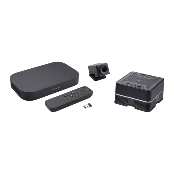
Package contents Your Meeting Computer System hardware kit package contains the following items: Meeting Computer System Wall mounting plate Power cable* Wall mounting plate screw set AC power adapter* Standing mount Camera Camera USB cable Technical documentations (Type-A to Type-C™) Speakermic Speakermic cable (Type-A to Micro USB) - Page 7 • If the device or its components fail or malfunction during normal and proper use within the warranty period, bring the warranty card to the ASUS Service Center for replacement of the defective components. • Some bundled accessories may vary with different models. For details on these accessories, refer to their respective user manuals.
- Page 8 GQE10A hardware kit...
-
Page 9: Getting To Know Your Meeting Computer System
Getting to know your Meeting Computer System... -
Page 10: Features
Features Rear view Power button The power button allows you to turn the Meeting Computer System on or off. You can use the power button to put your Meeting Computer System to sleep mode or press it for four (4) seconds to force shutdown your Meeting Computer System. - Page 11 USB 3.2 Gen 1 port The USB 3.2 Gen 1 (Universal Serial Bus) port provides a transfer rate up to 5 Gbit/s. This port also supports the Battery Charging 1.2 technology that allows you to charge your USB devices. NOTE: Battery Charging 1.2 technology is only available on selected models, and provides a maximum of 5V / 1.5A output.
-
Page 12: Left Side View
Left side view Air vents (exhaust vent) The air vents allow your Meeting Computer System chassis to expel hot air out. IMPORTANT! For an optimum heat dissipation and air ventilation, ensure that the air vents are free from obstructions. Right side view Air vents (intake vent) The air vents allow cooler air to enter your Meeting Computer System chassis. -
Page 13: Bottom View
Bottom view Mount pad slots The mount slots are used to attach the Meeting Computer System to the wall mounting plate or the standing mount. GQE10A hardware kit... - Page 14 GQE10A hardware kit...
-
Page 15: Using Your Meeting Computer System Hardware Kit
Using your Meeting Computer System hardware kit... -
Page 16: Getting Started
Getting started Connect a display panel to your Meeting Computer System You can connect a display panel or projector that has the following connectors: • HDMI™ connector • DisplayPort (USB Type-C ® • DVI connector (used with an HDMI™–DVI adapter) NOTE: •... -
Page 17: Connect The Speakermic
Connect the speakermic Connect the speakermic to a USB 3.2 Gen 1 port on the rear of your Meeting Computer System. NOTE: Please refer to pages 35-36 for more information on the recommended USB 3.2 Gen 1 port to connect the speakermic to. GQE10A hardware kit... -
Page 18: Connect The Camera
Connect the camera Connect the camera to a USB 3.2 Gen 1 port on the rear of your Meeting Computer System. NOTE: Please refer to pages 35-36 for more information on the recommended USB 3.2 Gen 1 port to connect the camera to. GQE10A hardware kit... -
Page 19: Connect The Touchscreen
Connect the touchscreen To connect the touchscreen to your Meeting Computer System NOTE: Ensure to use the Touchscreen USB data cable (Blue). A. Connect the Touchscreen USB data cable (Blue) to the data USB port on your touchscreen. Connect the touchscreen to a USB 3.2 Gen 1 port on the rear of your Meeting Computer System. - Page 20 To connect the AC power adapter of your touchscreen NOTE: Ensure to use the Touchscreen USB power cable (Red). A. Connect the Touchscreen USB power cable (Red) to the AC power adapter. Connect the Touchscreen USB power cable (Red) to the power USB port on your touchscreen.
- Page 21 To connect the touchscreen for local presentations (optional) NOTE: Ensure to use the Touchscreen HDMI™ cable (Green). A. Connect the Touchscreen HDMI™ cable (Green) to the HDMI™ port on your touchscreen. Connect the touchscreen to a device’s (such as a laptop) HDMI™ out port for local presentations.
-
Page 22: Connect The Ac Power Adapter To Your Meeting Computer System
Connect the AC power adapter to your Meeting Computer System To connect the AC power adapter to your Meeting Computer System: A. Connect the AC power cord to the AC/DC adapter. Connect the DC power connector into your Meeting Computer System’s power (DC) input port. - Page 23 IMPORTANT! • We strongly recommend that you use only the AC power adapter that came with your Meeting Computer System. • We strongly recommend that you use a grounded wall socket while using your Meeting Computer System. • The socket outlet must be easily accessible and near your Meeting Computer System.
-
Page 24: Turn On Your Meeting Computer System
Turn on your Meeting Computer System Press the power button to turn on your Meeting Computer System. IMPORTANT! Ensure that all peripherals (speakermic, camera, touchscreen) and AC power adapter are connected properly before you turn on your Meeting Computer System. GQE10A hardware kit... -
Page 25: Configuring Your Meeting Computer System Hardware Kit
Configuring your Meeting Computer System hardware kit... -
Page 26: Before You Begin Using Your Device For Video Conferencing
Before you begin using your device for video conferencing Setup requirements Room size and setup Your Meeting Computer System hardware kit system is designed for a 2-10 person conference room. We recommend a room that contains either a long table with the monitor at one end (optimal), or a round table. - Page 27 Display requirements and placement Your Meeting Computer System work with LCD, LED, plasma, and projector-type monitors and televisions. The display must have an HDMI™ or DisplayPort input. The screen resolution must be at least 1280 x 720 pixels. For best video quality, we recommend a resolution of 1920 x 1080 pixels.
-
Page 28: Setup Your System
• Cable concealers, if needed for wall mounting NOTE: The cable concealers for wall mounting and CAT5e Ethernet cable are not included in the package and must be purchased separately. IMPORTANT! The included cable for the camera is 5 feet long, and the included cable for the speakermic is 3 feet long. - Page 29 Secure the wall mount to a wall using the four (4) screws. NOTE: The screws are self tapping M3.5 24 mm long, flat countersunk head type screws. Locate the pill-shape on the bottom of your device and orientate it as shown in the illustration below so that the exhaust air vents faces upwards.
- Page 30 Your device will be magnetized onto the wall mount plate, please ensure the mount pad slots are aligned with the wall mount before placing the device onto the wall mount plate. NOTE: Please refer to Chapter 1 Getting to know your Meeting Computer System for more information on the location of the mount pad slots.
- Page 31 Using the standing mount To attach your Meeting Computer System to the bundled standing mount, please follow the steps below: Locate the pill-shape on the bottom of your device and orientate it as shown in the illustration below so that the exhaust air vents faces upwards.
- Page 32 Align your device’s mount pad slot to the standing mount, then bring the device closer to the mount. Your device will be magnetized and attach onto the standing mount. Manually adjust your device if needed for a more secure fit. GQE10A hardware kit...
- Page 33 Place your camera You may install your camera below or on top of the display depending on the screen height. NOTE: Keep the camera as close to eye level as possible. Recommended meeting room configuration 1 System setup GQE10A WALL MOUNT MEET CAMERA DISPLAY CHROMEBOX (WITH VESA MOUNT...
- Page 34 Recommended meeting room configuration 2 System setup GQE10A MEET CAMERA MEET CAMERA DISPLAY DISPLAY MICROPHONE & SPEAKER TOUCH PANEL CREDENZA RECOMMENDED HEIGHT BETWEEN CREDENZA 750 - 1000mm " - 39 "] CHROMEBOX OPTIONAL USB HUB FRONT WALL EXAMPLE EQUIPMENT LAYOUT CABLING (SURFACE/CONCEALED RUN) Room layout example...
- Page 35 Connect your cables Using the included cables and sensor, connect your Meeting Computer System to the other system components: NOTE: The connections shown in the illustrations are recommended, you may adjust the connections accordingly to suit your needs. LAN port connects to a router. NOTE: Although you can use your Meeting Computer System device over a wireless network connection, we recommend using a wired network connection for optimal sound and...
- Page 36 USB 3.2 Gen 1 port connects to the touchscreen HDMI™ connects a display with HDMI™ connector. DisplayPort connects a display with USB Type-C connector. ® Power port connects to a power outlet. IMPORTANT! Be sure to connect to a power outlet last, after you have made all the other connections.
-
Page 37: Enroll Your Device
Enroll your device Complete basic enrollment This section explains the basic enrollment flow, which works for almost all users. To learn about other options shown during the enrollment process, see Advanced enrollment options. NOTE: We recommend connecting a USB keyboard to make entering the enrollment information easier. - Page 38 Select Continue. Accept the Google Chrome OS Terms. Sign in with your Google Apps email address and password. The enrollment process takes place automatically. After the process is complete, click Done. When the Hangouts screen appears, follow the onscreen instructions to test your camera and speakermic. NOTE: If you can’t see video or hear audio during the test: •...
- Page 39 Advanced enrollment options Users can go through the simple enrollment flow described in Complete basic enrollment to enroll their device. Additional options are available for users who want to customize the setup experience or learn more. These options appear on the second enrollment screen, except for accessibility, which appears on both the first and second screens: Accessibility: Accessibility options include larger font and cursor...
-
Page 40: Manage Devices And Rooms
Manage devices and rooms You can view, modify and update your Meeting Computer System and rooms through the Google Admin console. For more details on managing your devices and rooms, please visit the Meeting Computer System Help website. GQE10A hardware kit... -
Page 41: Troubleshooting
Troubleshooting... -
Page 42: Fix A Problem
Fix a problem Manage devices and rooms I do not know how to identify the Meeting Computer System device I want on the device list screen. If you are not sure which device to click, you can identify the correct one by its serial number. -
Page 43: Appendix
Appendix... -
Page 44: Safety Information
Safety information Your Meeting Computer System is designed and tested to meet the latest standards of safety for information technology equipment. However, to ensure your safety, it is important that you read the following safety instructions. Setting up your system •... - Page 45 • If you encounter the following technical problems with the product, unplug the power cord and contact a qualified service technician or your retailer. – The power cord or plug is damaged. – Liquid has been spilled into the system. –...
-
Page 46: Regulatory Notices
Regulatory notices COATING NOTICE IMPORTANT! To provide electrical insulation and maintain electrical safety, a coating is applied to insulate the device except on the areas where the I/O ports are located. Federal Communications Commission Statement This device complies with Part 15 of the FCC Rules. Operation is subject to the following two conditions: (1) This device may not cause harmful interference, and (2) This device must accept any interference received, including... - Page 47 CAUTION! Changes or modification not expressly approved by the grantee of this device could void the user’s authority to operate the equipment. RF exposure warning This equipment must be installed and operated in accordance with provided instructions and the antenna(s) used for this transmitter must be installed to provide a separation distance of at least 20 cm from all persons and must not be co-located or operating in conjunction with any other antenna or transmitter.
- Page 48 Wireless Operation Channel for Different Domains N. America 2.412-2.462 GHz Ch01 through CH11 Japan 2.412-2.484 GHz Ch01 through Ch14 Europe ETSI 2.412-2.472 GHz Ch01 through Ch13 Regional notice for Singapore Complies with This ASUS product complies with IMDA Standards. IMDA Standards DB103778 GQE10A hardware kit...
- Page 49 ASUS follows the green design concept to design and manufacture our products, and makes sure that each stage of the product life cycle of ASUS product is in line with global environmental regulations. In addition, ASUS disclose the relevant information based on regulation requirements.
- Page 50 ASUS products sold in Vietnam, on or after September 23, 2011,meet the requirements of the Vietnam Circular 30/2011/TT-BCT. Các sản phẩm ASUS bán tại Việt Nam, vào ngày 23 tháng 9 năm2011 trở về sau, đều phải đáp ứng các yêu cầu của Thông tư 30/2011/TT- BCT của Việt Nam.
- Page 51 EPEAT (Electronic Product Environmental Assessment Tool) registered products The public disclosure of key environmental information for ASUS EPEAT registered products is available on CSR web site http://csr. asus.com/english/article.aspx?id=41. More information about EPEAT program and purchaser guidance can be found on the EPEAT website www.epeat.net.
- Page 52 Optical Drive Safety Information Laser Safety Information CLASS 1 LASER PRODUCT WARNING! To prevent exposure to the optical drive’s laser, do not attempt to disassemble or repair the optical drive by yourself. For your safety, contact a professional technician for assistance. Manufacturer ASUSTeK Computer Inc.
-
Page 53: Asus Contact Information
+1-510-608-4555 Web site http://www.asus.com/us/ Technical Support Support fax +1-812-284-0883 Telephone +1-812-282-2787 Online support https://www.asus.com/support/Product/ContactUs/Services/ questionform/?lang=en-us ASUS COMPUTER GmbH (Germany and Austria) Address Harkort Str. 21-23, 40880 Ratingen, Germany +49-2102-959931 Web site http://www.asus.com/de Online contact http://eu-rma.asus.com/sales Technical Support Telephone +49-2102-5789555 Support Fax...