Mitsubishi Electric E1032 Installation Manual
Hide thumbs
Also See for E1032:
- Installation manual (20 pages) ,
- Service and maintenance manual (65 pages)
Table of Contents
Quick Links
Table of Contents

Related Manuals for Mitsubishi Electric E1032


Summary of Contents for Mitsubishi Electric E1032
- Page 1 E1032 Installation Manual English MA00816D, 2014-12...
- Page 2 The information in this document is subject to change without notice and is provided as available at the time of printing. Mitsubishi Electric Automation Inc reserves the right to change any information without updating this publication. Mitsubishi Electric Automation Inc assumes no responsibility for any errors that may appear in this document.
-
Page 3: Table Of Contents
Screen and Keyboard Protector ........14 5 Operator Panel Drawings ..........15 Communication Ports ........... 15 E1032 Outline ........... 16 E1032 Text Strip ..........17 6 Additional Installation Tips ..........18 Grounding the Operator Panel ......... 18 Ethernet Connection in the Panel ......19 To Achieve Better EMC Protection ...... -
Page 4: Safety Precautions
UL and cUL Installation Caution: This section is only valid for UL labeled E1032 panels. • This equipment is suitable for use in non-hazardous locations only. [Combinations of equipment in your system are subject to investigation by the local authority having jurisdiction at the time of installation]. - Page 5 X1/X100 Anytek connectors AWG 24–12 • These devices are Class 2 supplied programmable controllers (industrial PCs) for the use in industrial control equipment and are intended to be (front) panel mounted (Type 1 and 4x for indoor use only). Mitsubishi Electric, MA00816D...
-
Page 6: During Installation
• Replacing the battery incorrectly may result in explosion. Only use batteries recommended by the supplier. During the warranty period, the battery needs to be replaced by an authorized Mitsubishi Electric service center. Dismantling and Scrapping • The operator panel or parts thereof shall be recycled according to local regulations. -
Page 7: Installation
1. Unpack and check the delivery. If damage is found, notify the supplier. Panel cut out 166 x 149 mm (6.54 x 5.87 inch) Note: Place the operator panel on a stable surface during installation. Dropping it or letting it fall may cause damage. Mitsubishi Electric, MA00816D... - Page 8 For text strip 7.0 mm (0.28 inch) 3. Secure the operator panel in position, using all the fastening holes and the provided brackets and screws: 0.5 - 1.0 Nm Mitsubishi Electric, MA00816D...
- Page 9 Connect cable C. – Connect cable D. – 5. Carefully remove the laminated film over the operator panel display, to avoid static electricity that could damage the panel. Mitsubishi Electric, MA00816D...
-
Page 10: Mode Switches
file for the driver in question. 2.2.3 Other Connections and Peripherals Cables, peripheral equipment and accessories must be suitable for the application and its environment. For further details or recommendations, please refer to the supplier. Mitsubishi Electric, MA00816D... -
Page 11: Technical Data
Horizontal installation: 0 ° to +40 °C Storage temperature -20 ° to +70 °C Relative humidity 5 - 85 % non-condensed Approvals and Information is available on the web site. certifications * See section Chemical Resistance for more information. Mitsubishi Electric, MA00816D... -
Page 12: Chemical Resistance
Phenol Xylene Ammonia, conc. Sodium hydroxide 5% 97 octan unleaded petrol Ethyl acetate Sodium hydroxide 30% 98 octan leaded petrol Screen and Overlay Material 4.2.1 Autotex F157/207 Autotex F157 or F207 covers the overlay surrounding the screen. Mitsubishi Electric, MA00816D... -
Page 13: Screen Surface
4.2.2 Screen Surface The screen surface on the operator panel withstands exposure to the following solvents without visible change: Solvents Time Acetone 10 minutes Isopropanol 10 minutes Toluene 5 hours Mitsubishi Electric, MA00816D... -
Page 14: Screen And Keyboard Protector
Screen and Keyboard Protector For harsh environments and exposure to outdoor conditions, it is recommended to use a protective film to guard the screen and the keyboard from damage. These optional parts can be ordered from Mitsubishi Electric. Mitsubishi Electric, MA00816D... -
Page 15: Operator Panel Drawings
Operator Panel Drawings Operator Panel Drawings Communication Ports RS-232 RS-422 RS-485 RS-422/485 Ethernet Mitsubishi Electric, MA00816D... -
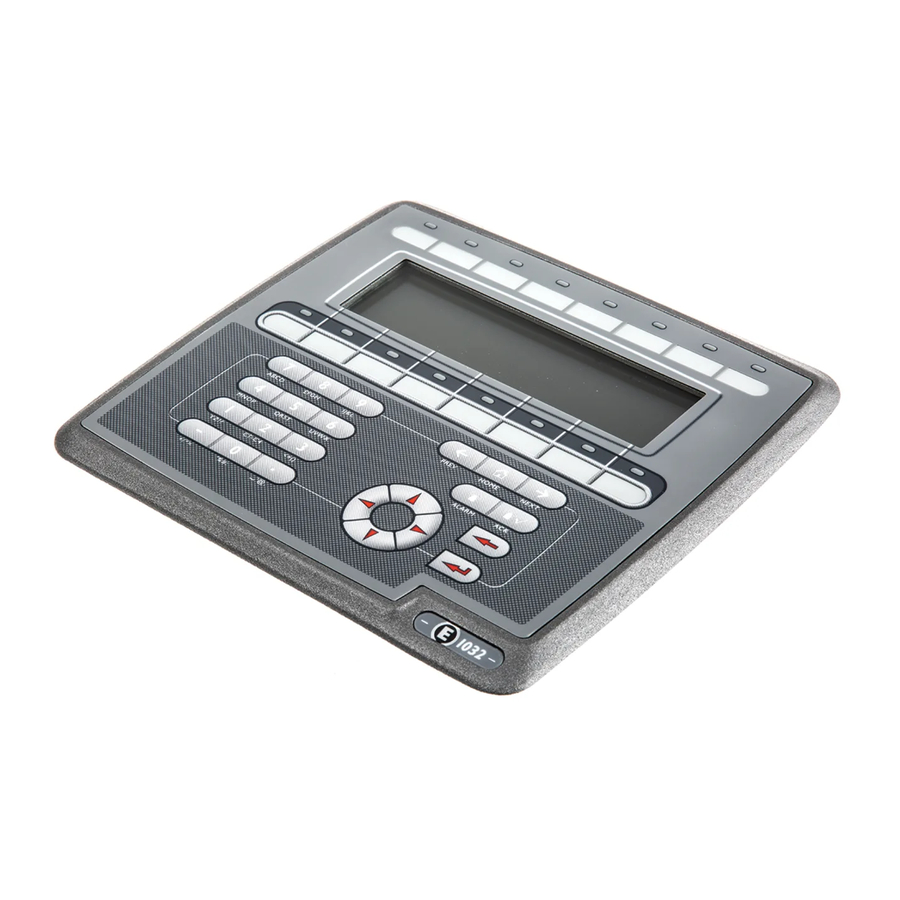
Page 16: E1032 Outline
Operator Panel Drawings E1032 Outline Mitsubishi Electric, MA00816D... -
Page 17: E1032 Text Strip
Operator Panel Drawings E1032 Text Strip Text max 17,0x8,0 Text max 18,5x8,0 Mitsubishi Electric, MA00816D... -
Page 18: Additional Installation Tips
Multi-wire conductors are better than single wire conductors with the same area. A braided conductor wire with the same area is even better. The best is a short, thick grounding braid. Mitsubishi Electric, MA00816D... -
Page 19: Ethernet Connection In The Panel
A more elegant method is to expand the shielded Ethernet cabling with a piece of unshielded Ethernet cable, see 4 in drawing above. You can ground the shield via an external 0.1 μ F/250 V plastic capacitor, see 5 in drawing above. This will connect the HF transients to the ground. Mitsubishi Electric, MA00816D... -
Page 20: To Achieve Better Emc Protection
Ferrite cores that are snapped onto the shielded cabling may remove minor disturbances. Large ferrite pieces that are snapped onto unshielded cabling and where the wires go 2-4 times around the cores are approximately 5-25 times more efficient. Mitsubishi Electric, MA00816D... -
Page 21: Ambient Temperature
An approximate value of the net power consumption for the operator panel can be calculated by multiplying the supply voltage with the current drawn by the operator panel. This is assuming that all supplied power is transformed to heat. Mitsubishi Electric, MA00816D... -
Page 22: Safety
Transients on the 24 V feed are connected to the ground. • No risk that the 24 V feed is at a high level in relationship to the ground. This is not unusual since there is high static electricity. Mitsubishi Electric, MA00816D... -
Page 23: Galvanic Isolation
24 V feed, disturbances and grounding currents from the 0 V on the 24 V side will disrupt communication. Using this type of unit solves one problem but creates a larger problem! A substandard installation may work now, but problems may arise when other devices are connected. Mitsubishi Electric, MA00816D... -
Page 24: Cable And Bus Termination Rs485
Set jumper pins 6-19. • Use CAB8. It offers the option of bus termination with pull-up/-down. It is also easy to connect the bus cable via the screw terminal block. See 4 in drawing above. Mitsubishi Electric, MA00816D... - Page 25 Mitsubishi Electric Automation, Inc. 500 Corporate Woods Parkway Vernon Hills, IL 60061, USA Mitsubishi Electric Europe B.V. Gothaer Strasse 8 D-40880 Ratingen, Germany...