
Related Manuals for Yamaha 01V


Summary of Contents for Yamaha 01V
- Page 1 Owner’s Manual Owner’s Manual interstage Phistersvej 31, 2900 Hellerup, Danmark Telefon 3946 0000, fax 3946 0040 www.interstage.dk - pro audio with a smile...
- Page 2 1. IMPORTANT NOTICE: DO NOT MODIFY THIS UNIT! This product, when installed as indicated in the instructions contained in this manual, meets FCC requirements. Modifications not expressly approved by Yamaha may void your authority, granted by the FCC, to use the product.
-
Page 3: Important Information
AC outlet. Consult your dealer for repair. Using the 01V in this condition is a fire and electrical shock hazard. • If you plan not to use the 01V for a long period of time, remove the power cord from the AC outlet. Leaving the 01V connected is a fire hazard. -
Page 4: Package Contents
If interference does occur, relocate the affected equipment. Copyright © 1998 Yamaha Corporation. All rights reserved. No part of the 01V software or this Owner’s Manual may be reproduced or distributed in any form or by any means without the prior written authorization of Yamaha Cor- poration. -
Page 5: Table Of Contents
01V System Example ........ - Page 6 About the 01V EQ ........
- Page 7 Omni Out Block Diagram ........118 Contents 01V—Owner’s Manual...
- Page 8 Protecting Scene Memories ........189 01V—Owner’s Manual...
- Page 9 Two 01Vs & two Tascam-Interface Recorders ....248 01V & Pro Tools (AES/EBU) ....... . . 250 Troubleshooting .
- Page 10 01V Dimensions ........
-
Page 11: Welcome To The 01V
Welcome to the 01V ........ -
Page 12: Welcome To The 01V
finishing up at the buses. 01V Installation Site the 01V on a stable surface, somewhere that complies with the important informa- tion at the front of this manual. The 01V can be rack-mounted using an optional rack-mount kit. 01V—Owner’s Manual... -
Page 13: 01V Features
01V Features 01V Sonic Specs • Linear 20-bit 128-times oversampling A/D converters • Linear 20-bit 8-times oversampling D/A converters (STEREO OUT) • 105 dB typical dynamic range (CH INPUT to STEREO OUT) • 20 Hz–20 kHz (+1, –3 dB) frequency response •... -
Page 14: Key Feature Discussion
Key Feature Discussion Configuration The 01V provides a total of 24 inputs: 12 mono input channels (1 through 12), 2 stereo input channels (13/14 and 15/16), and 8 digital inputs (17 through 24) by means of an Option I/O card. The stereo output signal is available from the analog STEREO OUT, coaxial DIGITAL STEREO OUT, and can be assigned to the analog OMNI OUTs and Option I/O digital outputs. - Page 15 D/A conversion, are virtually eliminated. Consequently, audio signal integrity is maintained from input through to output. The 01V can generate the industry standard sampling rate of 44.1 kHz, or synchronize to an external wordclock source from 44.1 kHz –10% to 48 kHz +6%.
- Page 16 “Digital Stereo In” on page 213 for more information. Easy-to-Learn GUI Interface 01V operation is both logical and intuitive. The 320 x 80 dot LCD display uses graphical icons to represent rotary controls, switches, and faders, and provides a clear indication of the current mix settings and EQ curves.
- Page 17 On many mixers, the only way to store mix settings is with marker pen and masking tape. With the 01V, however, virtually every mix setting can be stored in a mix scene using the 01V’s 99 scene memories. Mix scenes can be recalled instantly with just one button press, or remotely using MIDI Program Change commands.
- Page 18 Chapter 1—Welcome to the 01V 01V—Owner’s Manual...
-
Page 19: Getting Started
01V System Example ........ -
Page 20: System Example
Chapter 2—Getting Started 01V System Example This example shows the kind of system possible with the 01V. Personal computer running MIDI software MONITOR OUT Serial port MIDI IN MIDI interface MIDI OUT Drum machine MIDI IN Tone generator MIDI IN... -
Page 21: Important Wordclock Information
See “About Word- clocks” on page 206 for more information. If the 01V is the only digital audio device in your system, no special wordclock settings are required, and the 01V synchronizes to its own internal wordclock. Add a DAT recorder or digital multitrack recorder, however, and the system must be configured so... - Page 22 Chapter 2—Getting Started 01V—Owner’s Manual...
-
Page 23: Touring The 01V
Touring the 01V Touring the 01V In this chapter... Top Panel Controls ..........14 Inputs &... -
Page 24: Top Panel Controls
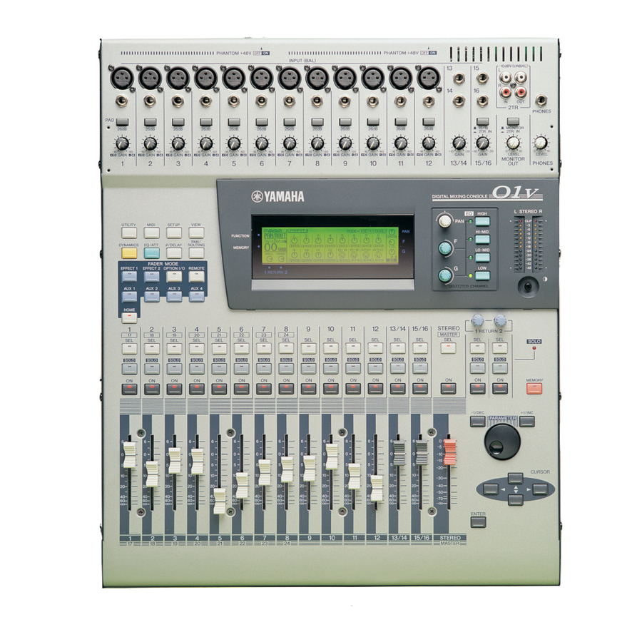
HOME SOLO SOLO SOLO SOLO SOLO SOLO ∞ ∞ ∞ ∞ ∞ ∞ The individual sections of the 01V are explained on the following pages. 01V—Owner’s Manual PHANTOM +48V INPUT (BAL) 26dB 26dB 26dB 26dB 26dB –16 –60 –16 –60 –16... - Page 25 GAIN –34 GAIN –34 GAIN –34 GAIN –34 Top Panel Controls 26dB 26dB 15/16 MONITOR 2TR IN 2TR IN –60 –16 –60 –20 –20 –20 GAIN GAIN LEVEL LEVEL GAIN –34 GAIN –34 MONITOR 13/14 15/16 PHONES 01V—Owner’s Manual –20...
- Page 26 AUTO SCREEN option is turned on, and an EQ control is adjusted, the EQ page appears automatically. Likewise, for the PANPOT AUTO SCREEN option and PAN control. See “Setting 01V Preferences” on page 203 for more information. Contrast This control is used to adjust the display contrast. Adjust it so that the display is clear and easy-to-read from your viewing position.
-
Page 27: Function Buttons
Input Meter, Rtn/Output Meter, Omni Out Meter, St Out Meter, HOME Metering Point Top Panel Controls VIEW MEMORY PAN/ ROUTING Pages FADER MODE EFFECT 2 OPTION I/O REMOTE AUX 1 AUX 2 AUX 3 AUX 4 HOME Pages 01V—Owner’s Manual... -
Page 28: Sel, Solo, On Buttons & Faders
Chapter 3—Touring the 01V SEL, SOLO, ON buttons & Faders SOLO SOLO SOLO SOLO SOLO SOLO ∞ ∞ ∞ ∞ ∞ ∞ SEL buttons The [SEL] buttons are used to select channels for parameter editing: input channels 1 through 24, effects returns 1 and 2, aux sends 1 through 4, effects sends 1 and 2, and the stereo output. - Page 29 238 for more information. Faders Depending on the selected fader mode, the 01V’s 60 mm motorized faders are used to control channel levels, aux send levels, or effects sends levels. Normally, faders 1 through 8 control channels 1 through 8. When the [OPTION I/O] button is pressed, however, they control input channels 17 through 24, which are only available when an Option I/O card is installed.
-
Page 30: Inputs & Outputs
Chapter 3—Touring the 01V Inputs & Outputs Input and output connectors are located on the top and rear panels. Top Panel PHANTOM +48V INPUT (BAL) 1–12 Input channels 1 through 12 feature balanced XLR-3-31-type and balanced phone jack connectors, both with a nominal input range of –60 dB to +10 dB. Phantom powering (+48 V) is supplied to the XLR connectors, with master on/off switches for connectors 1 through 6 and 7 through 12. - Page 31 Inputs & Outputs Phono plug Sleeve Phono plug Sleeve Tip (left) 1/4" TRS phone plug Ring (right) Sleeve (ground) 01V—Owner’s Manual...
-
Page 32: Rear Panel
Chapter 3—Touring the 01V Rear Panel CH 7-12 MONITOR OUT +4dB (BAL) MONITOR OUT These are balanced 1/4-inch phone jacks with a +4 dB nominal output level. Bal- anced or unbalanced phone plugs can be connected. They output the monitor sig- nals and should be connected to the inputs on a monitor amplifier. - Page 33 MIDI messages received at the MIDI IN port. TO HOST This 8-pin mini DIN port is used to connect the 01V to a personal computer for use with MIDI software. It eliminates the need for a computer MIDI interface, and together with the MIDI ports allows the 01V to be used as a MIDI interface for other MIDI equipment.
-
Page 34: Block Diagram
Chapter 3—Touring the 01V Block Diagram 01V—Owner’s Manual... - Page 35 Block Diagram 01V—Owner’s Manual...
- Page 36 Chapter 3—Touring the 01V 01V—Owner’s Manual...
-
Page 37: Getting Around The User Interface
Title Edit Dialog Box ..........37 01V—Owner’s Manual... -
Page 38: About The User Interface
Chapter 4—Getting Around the User Interface About the User Interface Thanks to a user-friendly interface, 01V operation is both logical and intuitive. The 320 x 80 dot LCD display provides clear indication of mix settings and operating status, while dedicated SELECTED CHANNEL controls allow for quick EQ and pan adjust- ments. - Page 39 As well as showing parameter values numerically, faders and rotary controls are represented graphically, so you can actually see pan and fader posi- tions. See “Display Elements” on page 30 for more information. An example page is shown below. 01V—Owner’s Manual...
-
Page 40: Display Elements
Pages such as VIEW and BUS MASTER display faders graphi- cally. To adjust a fader, use the cursor buttons to select it, and the PARAMETER wheel or [–1/DEC] and [+1/INC] buttons to set it. Fader knobs appear highlighted when set to the nominal posi- tion. 01V—Owner’s Manual Nominal... -
Page 41: Cursor Buttons
ON/OFF. It’s also used to confirm settings and enter characters when titling scene memories, effects programs, and so on. On the EQ page, the [ENTER] button is used solely to turn the EQ on and off. Cursor Buttons CURSOR PARAMETER –1/DEC +1/INC PARAMETER ENTER 01V—Owner’s Manual... -
Page 42: Fader Modes
Chapter 4—Getting Around the User Interface Fader Modes The 01V [SEL], [SOLO], and [ON] buttons, channel faders, and STEREO (MASTER) fader are multifunction controls, and their exact operation depends on the selected Fader mode. Operation of these controls is shown in the following tables. - Page 43 [HOME] button.) To solo input channel 20, press the [OPTION I/O] button, and then press [SOLO] but- ton 20. Fader Modes SOLO button 9–12 13/14 RETURN 1/2 15/16 RETURN 1/2 solo — — — — — — 01V—Owner’s Manual...
- Page 44 To turn on or off input channel 20, press the [OPTION I/O] button, and then press [ON] button 20. Master [ON] Button Examples To turn on or off the stereo output, press the [HOME] button, and then use the MAS- TER [ON] button. 01V—Owner’s Manual ON button 1–8 9–12 13/14 [17–24]...
- Page 45 RETURN 1 EFFECT EFFECT 2 master level RETURN 2 level STEREO — RETURN 1/2 levels master level — 01V—Owner’s Manual RETURN 1/2 1 send levels 2 send levels 3 send levels 4 send levels 1 send level 2 send level —...
- Page 46 PAN/ROUT page 3, use the cursor buttons to select the BUS 1 fader, and then adjust it using the PARAMETER wheel or [–1/DEC] and [+1/INC] buttons. Note: Bus out master levels can only be set using the virtual faders on PAN/ROUT page 3. 01V—Owner’s Manual...
-
Page 47: Title Edit Dialog Box
4. Use the [+1/INC] button to enter a space at the cursor position. 5. Use the [–1/DEC] button to t oggle the character at the cursor position between uppercase, lowercase, and numerals. 6. Press the [ENTER] button to store. Title Edit Dialog Box 01V—Owner’s Manual... - Page 48 Chapter 4—Getting Around the User Interface 01V—Owner’s Manual...
-
Page 49: Input Channels
Input Channel Block Diagram ........60 01V—Owner’s Manual... -
Page 50: Input Channel Overview
Chapter 5—Input Channels Input Channel Overview This section provides an overview of 01V input channels. Input Channels 1–12 XLR INPUT (balanced) Phone jack INPUT (balanced) Input Channels 13–16 Phone jacks INPUT (balanced) Input Channels 17–24 OPTION I/O 01V—Owner’s Manual Input channels 1 through 12 feature balanced XLR-3-31-type and balanced phone jack connectors, both with a nominal input range of –60 dB to +10 dB. -
Page 51: Phantom Powering
–10 dB to 20 dB. –20 GAIN GAIN control settings are not stored in scene memories. Metering Input Channels Signal levels can be metered on the HOME pages. See “Metering Signal Levels” on page 83 for more information. Phantom Powering 01V—Owner’s Manual... -
Page 52: Changing The Input Phase
The Phase switches on input channels 13 and 14 (likewise 15 and 16) are not linked, and can be set independently. When input channels 1 through 12 are paired (“Pairing Input Channels” on page 52), their Phase switches continue to work independently. Input channels 17 through 24 do not have Phase switches. 01V—Owner’s Manual... -
Page 53: Attenuating Input Channel Signals
1. Use the [OPTION I/O] button to locate OPTION page 2. 2. Use [SEL] buttons 17 through 24 to select channels. 3. Use the cursor buttons to select the ATT control, and the PARAMETER wheel or [–1/DEC] and [+1/INC] buttons to adjust it. Attenuating Input Channel Signals 01V—Owner’s Manual... -
Page 54: Applying Eq To Input Channels
Input channels 1 through 16 feature a dynamics processor. See “Dynamics Processors” on page 161 for more information. The dynamics can be turned on or off and the dynamics curve viewed on the Dynamics page and VIEW page. See “Viewing Input Channel Settings” on page 57 for more information. 01V—Owner’s Manual... -
Page 55: Delaying Channel Signals
These switches are used to turn on and off the delays. Delay can be specified in milliseconds, meters, or samples (“Setting 01V Preferences” on page 203). The maximum delay in samples is fixed at 11025. The maximum delay in milliseconds and meters depends on the sampling rate. At 44.1 kHz, for example, it is 250 milliseconds and 85.2... -
Page 56: Muting Input Channels
When input channels 1 through 12 are paired (“Pairing Input Chan- nels” on page 52), their faders are linked. Faders can be grouped together for multi-channel control using a single fader. See “Grouping Faders” on page 55 for more information. 01V—Owner’s Manual... -
Page 57: Panning Input Channels
“R” or “L” appears on the display next to the panpot icon. 2. Use the PAN control to pan the selected channel. If the PANPOT AUTO SCREEN option is turned on in the preferences (“Setting 01V Preferences” on page 203), the PAN/ROUT page shown below appears, and the Home fader mode is selected. - Page 58 GANG —In this mode, panpots are ganged (i.e., linked) together. INV. GANG —In this mode, panpots are ganged together but operation is inverted (i.e., panpots move in opposite directions). 01V—Owner’s Manual Hard left Center L16 ··· L3 L2 L1 CENTER R1 R2 R3 ··· R16...
-
Page 59: Routing Input Channels
(1, 2, 3, 4) and a stereo out routing switch (ST). Routing switches work in conjunction with Panpots to feed signals through to the left and right channels of the stereo out and the odd and even bus outs. The following table Routing Input Channels 01V—Owner’s Manual... -
Page 60: Monitoring Input Channels
Input channels 1 through 16 can be selected as sources for the Option I/O outs. See “Routing Input Channels” on page 49 and “About Option I/O Cards” on page 216 for more information. 01V—Owner’s Manual Signal Destination Signals are fed equally to bus outs 1 and 2 and the left and right channels of the stereo out. -
Page 61: Swapping Inputs 1-8 & 17-24
When channels are swapped, their meter numbers appear highlighted on HOME page 1 and OPTION page 1, as shown below. When a swapped channel is selected, the selected channel area of the display alternately shows the channel number and “SWAP”, also shown below. Swapping Inputs 1–8 & 17–24 01V—Owner’s Manual... -
Page 62: Pairing Input Channels
RESET BOTH —Reset both input channels to their initial settings. 2. Use the cursor buttons to select a pairing mode, and then press the [ENTER] button. The highlighted switch and STEREO label show that the input channels are now configured as a stereo pair. 01V—Owner’s Manual... - Page 63 On SETUP page 4, use the cursor buttons to select the paired channel switch, and then press the [ENTER] button. The following dialog box appears. 2. Select OK, and then press the [ENTER] button. The stereo pair is broken, and both input channels operate independently. Pairing Input Channels 01V—Owner’s Manual...
- Page 64 Chapter 5—Input Channels Input Channel Pair Block Diagram 01V—Owner’s Manual...
-
Page 65: Grouping Faders
1. Use the up and down cursor buttons to select the fader group that you want to disable: A, B, or C. 2. Use the [ENTER] button, PARAMETER wheel, or [–1/DEC] and [+1/INC] buttons to enable or disable the selected group. Fader group enabled Fader group disabled Grouping Faders 01V—Owner’s Manual... -
Page 66: Grouping Mutes
1. Use the up and down cursor buttons to select the mute group that you want to disable: D, E, or F. 2. Use the [ENTER] button, PARAMETER wheel, or [–1/DEC] and [+1/INC] buttons to enable or disable the selected group. Mute group enabled Mute group disabled 01V—Owner’s Manual... -
Page 67: Viewing Input Channel Settings
VIEW pages for input channels 13/14 and 15/16 appear as below. 2. Use [SEL] buttons 1 through 16 to select channels. 3. Use the cursor buttons to select the parameters, and the PARAMETER wheel, [–1/DEC], [+1/INC], and [ENTER] buttons to set them. Viewing Input Channel Settings 01V—Owner’s Manual... - Page 68 3. Use the cursor buttons to select the parameters, and the PARAMETER wheel, [–1/DEC], [+1/INC], and [ENTER] buttons to set them. Most of the parameters for input channels 17 through 24 can be set only on OPTION page 2. 01V—Owner’s Manual...
-
Page 69: Copying & Swapping Channel Settings
ALL —All input channel settings. EQ —EQ settings. DELAY —Delay settings. DYNAMICS —Dynamics settings. FADER —Fader settings. 4. Use the cursor buttons to select COPY or SWAP, and the [ENTER] button to execute the function. Copying & Swapping Channel Settings 01V—Owner’s Manual... -
Page 70: Input Channel Block Diagram
(BAL) from 2TR IN INPUT Unchanged (BAL) De-emphasis Option I/O 17-24 or DC Cut This section is available only when an optional Option I/O card is installed. 01V—Owner’s Manual Meter Meter 4-Band Dynamics Delay Meter Meter 4-Band Dynamics Delay 4-Band... - Page 71 About the 01V EQ ........
-
Page 72: About The 01V Eq
Chapter 6—EQ About the 01V EQ Input channels 1 through 16, the effects returns, aux sends, and stereo out all feature four-band parametric EQ, with variable gain, frequency, Q, and ON/OFF parameters. Input channels 17 through 24 feature a simplified two-band parametric EQ. See the “Block Diagram”... -
Page 73: Adjusting The Eq
F and G controls to adjust the frequency and gain, respec- tively. If the EQ AUTO SCREEN option is turned on in the preferences (“Setting 01V Prefer- ences” on page 203), the EQ page shown below appears, and the Home fader mode is selected. - Page 74 F and G controls to adjust the frequency and gain, respec- tively. If the EQ AUTO SCREEN option is turned on in the preferences (“Setting 01V Prefer- ences” on page 203), the EQ page shown below appears, and the Home fader mode is selected.
- Page 75 F and G controls to adjust the frequency and gain, respec- tively. If the EQ AUTO SCREEN option is turned on in the preferences (“Setting 01V Prefer- ences” on page 203), the EQ page shown below appears, and the Home fader mode is selected.
-
Page 76: Eq Specs
The following table contains the initial EQ values. Gain (G) Frequency (F) 1. Four-band EQs only (low and high bands only on input channels 17 through 24). 01V—Owner’s Manual Lo-Mid –18.0 dB to +18.0 dB (0.5 dB steps) 21 Hz–20.1 kHz (1/12 octave steps, 120 steps) HPF, 10.0–0.10... -
Page 77: Eq Library
Male Vocal 1 Male Vocal 2 Female Vo. 1 Female Vo. 2 Chorus&Harmo Total EQ 1 Total EQ 2 Total EQ 3 Bass Drum 3 Snare Drum 3 Tom-tom 2 Piano 3 Piano Low Piano High Fine-EQ Cass Narrator 01V—Owner’s Manual... -
Page 78: Storing Eq Programs
The Title Edit dialog box appears. If the STORE CONFIRMATION option is turned off in the preferences (“Setting 01V Preferences” on page 203), the Title Edit dialog box does not appear and the EQ program is stored. 5. Enter a title for the EQ program. -
Page 79: Recalling Eq Programs
The EQ program is recalled. If the RECALL CONFIRMATION option is turned on in the preferences (“Setting 01V Preferences” on page 203), a confirmation dialog box appears. In this case, select OK, and then press the [ENTER] button to confirm the recall. -
Page 80: Editing Eq Program Titles
The Title Edit dialog box appears. 4. Edit the program title. See “Title Edit Dialog Box” on page 37 for more information. 5. When you’ve finished, select OK, and then press the [ENTER] button. The new title is stored. 01V—Owner’s Manual... -
Page 81: Preset Eq Program Parameters
— H.SHELF Makes a tight electric 0.0 dB bass sound by cutting 4.00 kHz very low frequencies. — H.SHELF Unlike program 9, this +0.5 dB program emphasizes the low range of an 4.00 kHz electric bass. — 01V—Owner’s Manual... - Page 82 Chapter 6—EQ Title Syn.Bass 1 Syn.Bass 2 Piano 1 Piano 2 E.G.Clean E.G.Crunch 1 E.G.Crunch 2 E.G.Dist. 1 E.G.Dist. 2 A.G.Stroke 1 01V—Owner’s Manual Parameter L-MID H-MID PEAKING PEAKING PEAKING +3.5 dB +8.5 dB 0.0 dB 83 Hz 944 Hz 4.00 kHz...
- Page 83 Use as a template for a +3.0 dB chorus. It makes the entire chorus much 4.49 kHz brighter. H.SHELF Use on a stereo mix dur- +6.5 dB ing mixdown. Sounds even better when used 16.0 kHz with a compressor. — 01V—Owner’s Manual...
- Page 84 Title Total EQ 2 Total EQ 3 Bass Drum 3 Snare Drum 3 Tom-tom 2 Piano 3 Piano Low Piano High Fine-EQ Cass Narrator 01V—Owner’s Manual Parameter L-MID H-MID PEAKING PEAKING PEAKING +4.0 dB +1.5 dB +2.0 dB 94 Hz 749 Hz 1.78 kHz...
-
Page 85: Solo, Monitors & Meters
Effects Send Meters ..........86 01V—Owner’s Manual... -
Page 86: About Monitor & Solo
Chapter 7—Solo, Monitors & Meters About Monitor & Solo Flexible monitoring and solo functions mean the 01V can be used in a wide range of applications. All inputs and outputs can be monitored pre or post fader via the monitor out or phones. -
Page 87: Monitor Outputs
Normally, the input signals for these input channels are derived from phone jack inputs 15 and 16. The 2TR OUT jacks are explained on page 88. Monitor Outputs MONITOR OUT +4dB(BAL) LEVEL MONITOR PHONES LEVEL PHONES –10dBV (UNBAL) MONITOR 2TR IN 15/16 2TR IN 01V—Owner’s Manual... -
Page 88: Monitor Setup
4. Use the [SETUP] button to locate SETUP page 2, explained previously. 5. Set the SOURCE to STEREO OUT. If MONITOR SETUP LISTEN is set to AFL, the STEREO fader must be raised. Other- wise, you won’t hear anything. 01V—Owner’s Manual... -
Page 89: Monitor Block Diagram
LISTEN Meter Meter master fader LISTEN DIGITAL STEREO ST CASCADE IN from LISTEN MONITOR 2TR IN LEVEL LEVEL Monitor Block Diagram 2TR OUT STEREO DIGITAL STEREO Dither OUTPUT SELECT MONI OUTPUT SELECT OUTPUT SELECT MONITOR PHONES 01V—Owner’s Manual... -
Page 90: Solo Setup
Stereo bus. In this mode, the MONITOR SETUP LISTEN switch can be used to select either PFL or AFL. SOLO TRIM —This parameter is used to adjust the level of the solo signal from –60 dB to +6 dB. 01V—Owner’s Manual... -
Page 91: Using Solo
8. Use the effects returns [SOLO] buttons to solo effects returns 1 and 2. When a channel is soloed, its [SOLO] button and the main SOLO indicator flash. If SOLO SETUP LISTEN is set to AFL, you must raise the soloed channel’s fader. Oth- erwise, you won’t hear anything. Using Solo 01V—Owner’s Manual... -
Page 92: Solo Block Diagram
Chapter 7—Solo, Monitors & Meters Solo Block Diagram 01V—Owner’s Manual... -
Page 93: Metering Signal Levels
Meters for the effects returns also appear on the EFFECT and VIEW pages. See “Using the Effects” on page 123 and “Viewing Effects Returns Settings” on page 130. Meters for the aux sends also appear on the VIEW pages. See “Viewing Aux Send Settings” on page 98 for more information. 01V—Owner’s Manual... -
Page 94: Main Stereo Meters
Peak Hold function on or off. To reset the Peak Hold function, turn it off and then on again. 01V—Owner’s Manual In addition to the meters on HOME page 4, stereo output levels are displayed on the dedicated 12-segment main stereo meters, with Peak Hold. -
Page 95: Setting The Metering Point
Signal level meters for the Option I/O outputs are displayed on OPTION page 3, as shown below. The source assigned to each output is displayed below its meter. These assignments are made on OPTION page 4. See “Assigning Option I/O Digital Outputs” on page 219 for more information. Setting the Metering Point 01V—Owner’s Manual... -
Page 96: Effects Send Meters
2. Use the [VIEW] button to locate VIEW pages 1 and 2, as shown below. Signal level meters for effects send 1 are displayed on VIEW pages 1 and 2, as shown below. Signal level meters for effects send 2 are displayed on VIEW pages 1 and 2, as shown below. 01V—Owner’s Manual... -
Page 97: Stereo Output
Stereo Output Block Diagram ........92 01V—Owner’s Manual... -
Page 98: About The Stereo Output
Setup” on page 80 for more information. Monitoring the Stereo Output The stereo output can be monitored using the monitor out or phones. See “Monitor Setup” on page 78 for more information. 01V—Owner’s Manual STEREO OUT +4dB(BAL) –10dBV (UNBAL) DIGITAL STEREO... -
Page 99: Metering The Stereo Output
2. Use the [VIEW] button to locate VIEW pages 1 and 2, as shown below. 3. Use the cursor buttons to select the parameters, and the PARAMETER wheel, [–1/DEC], [+1/INC], and [ENTER] buttons to set them. Parameters are explained in the following sections. Metering the Stereo Output 01V—Owner’s Manual... -
Page 100: Setting The Stereo Output Level
VIEW page. See “Viewing Stereo Output Settings” on page 89 for more information. 01V—Owner’s Manual The stereo output level is controlled using the STEREO fader. Since this fader is also used to control the aux and effects send master levels, you may need to press the [HOME] button before adjusting the stereo output level. -
Page 101: Stereo Output Delay
These switches are used to turn on and off the delays. Delay can be specified in milliseconds, meters, or samples (“Setting 01V Preferences” on page 203). The maximum delay in samples is fixed at 13229. The maximum delay in milliseconds and meters depends on the sampling rate. At 44.1 kHz, for example, it is 300 milliseconds and 102.2... -
Page 102: Stereo Output Block Diagram
Chapter 8—Stereo Output Stereo Output Block Diagram 1 2 3 4 4-Band 4-Band 01V—Owner’s Manual Meter Meter Dynamics Delay BALANCE Dynamics Delay STEREO OUT LISTEN 2TR OUT STEREO DIGITAL STEREO Dither OUTPUT SELECT MONI... -
Page 103: Aux Sends
Stereo Pair Aux Send Block Diagram ....... . 105 01V—Owner’s Manual... -
Page 104: About The Aux Sends
Chapter 9—Aux Sends About the Aux Sends The 01V’s four aux sends, which can be used individually or in stereo pairs, feature four-band parametric EQ and dynamics processors. Signals from input channels 1 through 16 and the effects returns can be sent to aux sends 1 through 4, while those from input channels 17 through 24 can be sent to aux sends 1 and 2. -
Page 105: Sending Channel Signals To Aux Sends
If the aux send is configured post-fader (“Pre-fader/Post-fader Aux Sends” on page 97), you’ll have to raise the channel’s regular fader as well. If the Option I/O fader mode is still selected, simply raise the fader. Sending Channel Signals to Aux Sends 01V—Owner’s Manual... - Page 106 If the aux send is configured post-fader (“Pre-fader/Post-fader Aux Sends” on page 97), you’ll have to raise the effects returns regular control as well. To do this, press the [HOME] button, and then turn up the rotary control. 01V—Owner’s Manual...
-
Page 107: Pre-Fader/Post-Fader Aux Sends
3. Use the cursor buttons to select the AUX PRE/POST switches, and the PARAMETER wheel or [–1/DEC] and [+1/INC] buttons to set them. When aux 1 and 2 are paired (“Pairing Aux Sends” on page 101), the PRE/POST switches are linked. Pre-fader/Post-fader Aux Sends 01V—Owner’s Manual... -
Page 108: Viewing Aux Send Settings
2. Use the [VIEW] button to locate VIEW pages 1 and 2, as shown below. 3. Use the cursor buttons to select the parameters, and the PARAMETER wheel, [–1/DEC], [+1/INC], and [ENTER] buttons to set them. Parameters are explained in the following sections. 01V—Owner’s Manual... -
Page 109: Setting Aux Send Master Levels
When aux sends are paired (“Pairing Aux Sends” on page 101), their master faders are linked. The aux send master levels can be viewed and adjusted on the VIEW pages. See “View- ing Aux Send Settings” on page 98 for more information. Setting Aux Send Master Levels 01V—Owner’s Manual... -
Page 110: Muting Aux Sends
Each aux send features a dynamics processor. See “Dynamics Processors” on page 161 for more information. The dynamics can be turned on or off, and the dynamics curve viewed on the VIEW page. See “Viewing Aux Send Settings” on page 98 for more infor- mation. 01V—Owner’s Manual... -
Page 111: Pairing Aux Sends
1. On SETUP page 4, use the cursor buttons to select the paired aux switch, and then press the [ENTER] button. The following dialog box appears. 2. Select OK, and then press the [ENTER] button. The stereo pair is broken, and both aux sends operate independently. Pairing Aux Sends 01V—Owner’s Manual... - Page 112 With the inner control set at L16 and the outer control set at R16, as shown here, the width of a stereo signal is 100%. With both controls set at CENTER, as shown here, the width of the stereo signal is zero (i.e., mono). 01V—Owner’s Manual Center Hard right...
- Page 113 Setting the controls to positions in between these two extremes allows you to set the width of the stereo signal. To maintain a central balance, however, you must set both controls to corresponding values. For example, L8 and R8, or L10 and R10. 01V—Owner’s Manual...
-
Page 114: Aux Send Block Diagram
Chapter 9—Aux Sends Aux Send Block Diagram 1 2 3 4 01V—Owner’s Manual Meter Meter AUX 1 master fader 4-Band Dynamics LISTEN Meter Meter AUX 2 master fader 4-Band Dynamics LISTEN Meter Meter AUX 3 master fader 4-Band Dynamics LISTEN... -
Page 115: Stereo Pair Aux Send Block Diagram
Stereo Pair Aux Send Block Diagram Stereo Pair Aux Send Block Diagram 01V—Owner’s Manual... - Page 116 Chapter 9—Aux Sends 01V—Owner’s Manual...
-
Page 117: Bus Outs
Stereo Pair Bus Out Block Diagram ....... . . 113 01V—Owner’s Manual... -
Page 118: About The Bus Outs
Chapter 10—Bus Outs About the Bus Outs The 01V’s four bus outs can be used individually or in stereo pairs. Signals from input channels 1 through 24 and the effects returns can be routed to bus outs 1 through 4. See “Routing Input Channels”... -
Page 119: Setting Bus Out Master Levels
When bus outs are paired (“Pairing Bus Outs” on page 111), their ON switches are linked. Bus outs can be muted using regular [ON] buttons on REMOTE page 1. See “Assigning Faders & On Buttons” on page 194 for more information. Setting Bus Out Master Levels 01V—Owner’s Manual... -
Page 120: Routing Bus Signals To The Stereo Bus
3. Use the cursor buttons to select the panpots, and the PARAMETER wheel or [–1/DEC] and [+1/INC] buttons to set them. Including center, there are 33 pan positions. Hard left L16 ··· L3 L2 L1 CENTER R1 R2 R3 ··· R16 01V—Owner’s Manual Center Hard right... -
Page 121: Pairing Bus Outs
1. On SETUP page 4, use the cursor buttons to select the paired bus switch, and then press the [ENTER] button. The following dialog box appears. 2. Select OK, and then press the [ENTER] button. The stereo pair is broken, and both bus outs operate independently. Pairing Bus Outs 01V—Owner’s Manual... -
Page 122: Bus Out Block Diagram
Chapter 10—Bus Outs Bus Out Block Diagram 1 2 3 4 01V—Owner’s Manual Meter Meter BUS 1 master fader LISTEN TO ST Meter Meter BUS 2 master fader LISTEN TO ST Meter Meter BUS 3 master fader LISTEN TO ST... -
Page 123: Stereo Pair Bus Out Block Diagram
BUS 2 LISTEN TO ST BUS 3 Meter master fader BUS 3 LISTEN TO ST BUS 4 Meter master fader BUS 4 LISTEN TO ST BUS 1 Unchanged BUS 2 Unchanged BUS 3 Unchanged BUS 4 Unchanged 01V—Owner’s Manual... - Page 124 Chapter 10—Bus Outs 01V—Owner’s Manual...
-
Page 125: Omni Outs
Omni Out Block Diagram ......... 118 01V—Owner’s Manual... -
Page 126: About The Omni Outs
Chapter 11—Omni Outs About the Omni Outs The 01V’s four omni outs can be used as aux send outputs, bus out outputs, additional stereo outputs, or post-fader direct outputs for input channels 1 through 16. Each omni out features a variable output delay of up to 300 milliseconds. -
Page 127: Omni Out Delay
These switches are used to turn on and off the delays. Delay can be specified in milliseconds, meters, or samples (“Setting 01V Preferences” on page 203). The maximum delay in samples is fixed at 13229. The maximum delay in milliseconds and meters depends on the sampling rate. At 44.1 kHz, for example, it is 300 milliseconds and 102.2... -
Page 128: Omni Out Block Diagram
Chapter 11—Omni Outs Omni Out Block Diagram STEREO L STEREO R BUS 1 BUS 4 AUX 1 from AUX 4 CH 1 CH 2 CH 15 CH 16 01V—Owner’s Manual OMNI OUT Select Delay OMNI... -
Page 129: Effects
Effects Block Diagram ..........159 01V—Owner’s Manual... -
Page 130: About The Onboard Effects
Chapter 12—Effects About the Onboard Effects The 01V’s two onboard stereo multi-effects processors, Effect 1 and Effect 2, provide a wide range of high-quality effects, including reverb, delay, chorus, flange, amp simula- tor, and freeze. There are 42 different types of effect available. Effects processors 1 and 2 are fed by Effect buses 1 and 2, respectively, and processed signals are returned via effect returns 1 and 2. -
Page 131: Preset Effects Programs
Description Three-phase stereo chorus. The well-known flanging effect. A Yamaha proprietary effect that produces a richer and more complex modulation than chorus. Stereo phaser with 2–16 stages of phase shift. An effect which cyclically moves the sound between left and right. -
Page 132: Dynamic Effects
An effect that modifies the pitch by applying amplitude modulation to the frequency of the input. RING MOD. On the 01V, even the modulation frequency can be controlled by modulation. An effect which uses an LFO to modulate the MOD.FILTER frequency of the filter. -
Page 133: Using The Effects
This step is necessary because effects sends are initially configured as post-fader sends. If the channel fader is not raised, no signal is fed to the effects sends. See “Pre-fader/Post-fader Effects Sends” on page 125 for more information. Using the Effects 01V—Owner’s Manual... - Page 134 The processed signal is returned into the mix. 3. Set the EQ, pan, and so on for the effects return channel. Effects programs can be recalled from the effects library. See “Recalling Effects Pro- grams” on page 134 for more information. 01V—Owner’s Manual...
-
Page 135: Pre-Fader/Post-Fader Effects Sends
The PRE/POST switches on input channels 13 and 14 (likewise 15 and 16) are perma- nently linked. When input channels 1 through 12 are paired (“Pairing Input Channels” on page 52), their PRE/POST switches are linked. Pre-fader/Post-fader Effects Sends 01V—Owner’s Manual... - Page 136 1. Use the [OPTION I/O] button to locate OPTION page 2, as shown below. 2. Use [SEL] buttons 17 through 24 to select channels. 3. Use the cursor buttons to select the EFFECT PRE/POST switches, and the PARAMETER wheel or [–1/DEC] and [+1/INC] buttons to set them. 01V—Owner’s Manual...
-
Page 137: Viewing Effects Send Settings
[–1/DEC], [+1/INC], and [ENTER] buttons to set them. Parameters are explained in the following sections. Metering Effects Sends Effects sends signal levels can be metered on the VIEW pages. See “Viewing Effects Send Settings” on page 127 for more information. Viewing Effects Send Settings 01V—Owner’s Manual... -
Page 138: Setting Effects Send Master Levels
The effects send master levels can be viewed and adjusted on the VIEW pages. See “Viewing Effects Send Settings” on page 127 for more information. 01V—Owner’s Manual Effects send master levels are controlled using the MASTER fader. The function of this fader depends on the selected Fader mode. See “Fad-... -
Page 139: Muting Effects Sends
2. Use the MASTER [ON] button to turn the effects send on or off. The effects send master switches can be viewed and set on the VIEW pages. See “View- ing Effects Send Settings” on page 127 for more information. Muting Effects Sends 01V—Owner’s Manual... -
Page 140: Viewing Effects Returns Settings
See “Viewing Effects Returns Settings” on page 130 for more information. Muting Effects Returns Effects returns can be turned on and off (i.e., muted) using the effects returns [ON] buttons. When an effects returns is on, its [ON] button lights up. 01V—Owner’s Manual... -
Page 141: Setting Effects Returns Levels
Signals from effects returns 1 and 2 can be sent to aux sends 1 through 4. Effects return sends can be configured as either pre-fader or post-fader sends. When aux sends are paired, aux send panpots become available on each effects return. See “Aux Sends” on page 93 for more information. Setting Effects Returns Levels 01V—Owner’s Manual... -
Page 142: Effects Library
Below these is the library window, which can be scrolled using the PARAME- TER wheel. The “R” icon next to a preset program means read only. The meters indicate effects returns signal levels for the selected effects processor. 01V—Owner’s Manual... -
Page 143: Storing Effects Programs
[ENTER] button. The Title Edit dialog box appears. If the STORE CONFIRMATION option is turned off in the preferences (“Setting 01V Preferences” on page 203), the Title Edit dialog box does not appear and the effects program is stored. 4. Title the effects program. -
Page 144: Recalling Effects Programs
The effects program is recalled. If the RECALL CONFIRMATION option is turned on in the preferences (“Setting 01V Preferences” on page 203), a confirmation dialog box appears. In this case, select OK, and then press the [ENTER] button to confirm the recall. -
Page 145: Editing Effects Program Titles
The Title Edit dialog box appears. 4. Edit the program title. See “Title Edit Dialog Box” on page 37 for more information. 5. Select OK, and then press the [ENTER] button. The program is stored with its new title. Editing Effects Program Titles 01V—Owner’s Manual... -
Page 146: Editing Effects
Effects parameters, including variable range and description, are listed on page 138. To store the edited program, see “Storing Effects Programs” on page 133. 01V—Owner’s Manual... -
Page 147: Setting Delay, Freq, Note & Tempo Parameters
To use Tap Tempo, select the TAP TEMPO switch, and then press the [ENTER] button on each beat. The TEMPO is calculated automatically based on the time between each button press. Only the DELAY and FREQ. parameters can be controlled by using MIDI Control Change and System Exclusive Parameter Change messages. 01V—Owner’s Manual... -
Page 148: Effects Parameters
Early reflections. Parameter TYPE ROOMSIZE 0.1–20.0 LIVENESS INI.DLY DIFF. DENSITY ER NUM. FB GAIN HI.RATIO 01V—Owner’s Manual Range 0.3–99.9 s Reverb time 0.0–500.0 ms Initial delay before reverb begins 0.1–1.0 High-frequency reverb time ratio 0.1–2.4 Low-frequency reverb time ratio 0–10 Reverb diffusion (left–right reverb spread) -
Page 149: Mono Delay
Used in conjunction with TEMPO to determine DELAY Feedback gain (plus values for normal-phase feedback, minus values for reverse-phase feedback) High-frequency feedback ratio High-pass filter cutoff frequency Low-pass filter cutoff frequency Used in conjunction with NOTE to determine DELAY (Maximum value depends 01V—Owner’s Manual... -
Page 150: Stereo Delay
TEMPO on the tempo setting) 3. For more information about the DELAY, NOTE, and TEMPO parameters, see “Setting Delay, Freq, Note & Tempo Parameters” on page 137. 01V—Owner’s Manual Range 0.0–1350.0 ms Left channel delay time Used in conjunction with TEMPO to determine left... - Page 151 Feedback gain (plus values for normal-phase feedback, minus values for reverse-phase feedback) High-frequency feedback ratio High-pass filter cutoff frequency Used in conjunction with NOTE parameters to determine DELAY L, DELAY C, DELAY R, and FB.DLY (Maximum value depends 01V—Owner’s Manual...
- Page 152 WAVE TEMPO 2. For more information about the FREQ., NOTE, and TEMPO parameters, see “Setting Delay, Freq, Note & Tempo Parameters” on page 137. 01V—Owner’s Manual Range 0.0–1350.0 ms Left channel delay time Used in conjunction with TEMPO to determine DELAY Left channel feedback gain (plus values for –99 to +99%...
- Page 153 Used in conjunction with NOTE to determine FREQ. Description Modulation speed Used in conjunction with TEMPO to determine FREQ. Modulation depth Feedback gain (plus values for normal-phase feedback, minus values for reverse-phase feedback) Lowest phase-shifted frequency offset Used in conjunction with NOTE to determine FREQ. 01V—Owner’s Manual...
- Page 154 TEMPO the tempo setting) 2. For more information about the DELAY, NOTE, and TEMPO parameters, see “Setting Delay, Freq, Note & Tempo Parameters” on page 137. 01V—Owner’s Manual Range 0.05–40.00 Hz Modulation speed Used in conjunction with TEMPO to determine FREQ.
- Page 155 Used in conjunction with NOTE parameters to determine DELAY L and DELAY R (Maximum value depends on Description Rotation stop, start Rotation speed (see SLOW and FAST parameters) Overdrive level Accelation at speed changes Low-frequency filter High-frequency filter SLOW rotation speed FAST rotation speed 01V—Owner’s Manual...
-
Page 156: Ring Mod
Delay, Freq, Note & Tempo Parameters” on page 137. DISTORTION Distortion effect. Parameter DST TYPE DRIVE MASTER TONE N.GATE 01V—Owner’s Manual Range OSC, SELF Modulation source: oscillator or input signal 0.0–3000.0 Hz Oscillator frequency 0.05–40.00 Hz Oscillator frequency modulation speed Used in conjunction with TEMPO to determine FM FREQ 0–100%... - Page 157 Filter frequency change decay speed Description Control source: input signal or MIDI note on velocity Sensitivity Feedback gain (plus values for normal-phase feedback, minus values for reverse-phase feedback) Delay time offset Upward or downward frequency change Decay speed 01V—Owner’s Manual...
- Page 158 WAVE REV/CHO TEMPO 2. For more information about the FREQ., NOTE, and TEMPO parameters, see “Setting Delay, Freq, Note & Tempo Parameters” on page 137. 01V—Owner’s Manual Range INPUT, MIDI Control source: input signal or MIDI note on velocity 0–100...
- Page 159 Modulation delay time Feedback gain (plus values for normal-phase feedback, minus values for reverse-phase feedback) Modulation waveform Reverb and flange balance (0% = flange, 100% = reverb) High-pass filter cutoff frequency Used in conjunction with NOTE to determine FREQ. 01V—Owner’s Manual...
- Page 160 MOD.DLY WAVE REV/SYM TEMPO 2. For more information about the FREQ., NOTE, and TEMPO parameters, see “Setting Delay, Freq, Note & Tempo Parameters” on page 137. 01V—Owner’s Manual Range 0.3–99.9 s Reverb time 0.0–500.0 ms Initial delay before reverb begins 0.1–1.0...
- Page 161 Used in conjunction with TEMPO to determine FREQ. Modulation depth Panning direction Modulation waveform Reverb and panned reverb balance (0% = panned reverb, 100% = reverb) High-pass filter cutoff frequency Low-pass filter cutoff frequency Used in conjunction with NOTE to determine FREQ. 01V—Owner’s Manual...
- Page 162 TEMPO on the tempo setting) 2. For more information about the DELAY, NOTE, and TEMPO parameters, see “Setting Delay, Freq, Note & Tempo Parameters” on page 137. 01V—Owner’s Manual Range 0.0–1000.0 ms Left channel delay time Used in conjunction with TEMPO to determine left...
- Page 163 Early reflections decay characteristics (0 = dead, 10 = live) Initial delay before reverb begins Reverb density Number of early reflections Used in conjunction with NOTE parameters to determine DELAY L, DELAY R, and FB.DLY (Maximum value depends on 01V—Owner’s Manual...
- Page 164 TEMPO the tempo setting) 2. For more information about the DELAY, NOTE, and TEMPO parameters, see “Setting Delay, Freq, Note & Tempo Parameters” on page 137. 01V—Owner’s Manual Range 0.0–1000.0 ms Left channel delay time Used in conjunction with TEMPO to determine left...
- Page 165 100% = delay) Reverb time Initial delay before reverb begins High-frequency reverb time ratio Reverb density High-pass filter cutoff frequency Used in conjunction with NOTE parameters to determine DELAY L, DELAY R, and FB.DLY (Maximum value depends on 01V—Owner’s Manual...
- Page 166 FREQ. 1 FREQ. 2 FREQ. 3 LEVEL 1 LEVEL 2 LEVEL 3 RESO. 1 RESO. 2 RESO. 3 01V—Owner’s Manual Range DST1, DST2, OVD1, Distortion type (DST = distortion, OVD = overdrive) OVD2, CRUNCH 0–100 Distortion drive 0–100 Master volume –10 to +10...
- Page 167 For minus values, recording starts before the trigger is received. Once playback has been triggered, subsequent triggers are ignored for the duration of the TRG MASK time. Sample playback can be triggered using MIDI Note on/off messages. Playback pitch shift fine 01V—Owner’s Manual...
- Page 168 Use the PLY MODE parameters to set the type of playback, and the START, END, and LOOP parameters to edit the sample. Be aware that samples are lost when another type of effect is recalled or the 01V is turned off.
-
Page 169: Effects Block Diagram
AUX2 AUX3 AUX4 EFF2 AUX/EFF PRE/POST EFF RTN 2 Rotary PAN* AUX1 AUX2 AUX3 AUX4 EFF1 AUX/EFF PRE/POST *PAN: INDIVIDUAL/GANG/INV. GANG Effects Block Diagram 1 2 3 4 Effect send 1 master fader Effect send 2 master fader 01V—Owner’s Manual... - Page 170 Chapter 12—Effects 01V—Owner’s Manual...
-
Page 171: Dynamics Processors
Preset Dynamics Program Settings ........177 01V—Owner’s Manual... -
Page 172: About The Dynamics Processors
The GR meter indicates the amount of gain reduction being applied to the selected channel. Next to this are level meters for the selected channel and its neighbor. 01V—Owner’s Manual... -
Page 173: Preset Dynamics Programs
Sampling SN Hip Comp Solo Vocal1 Solo Vocal2 Chorus Click Erase Announcer Limiter1 Limiter2 Total Comp1 Total Comp2 Type COMP COMP COMP COMP COMP COMP COMP COMPAND-S COMP COMP COMPAND-S COMP COMP COMP EXPAND COMPAND-H COMPAND-S COMP COMP COMP 01V—Owner’s Manual... -
Page 174: Using The Dynamics Processors
3. Press the [ENTER] button to turn on the dynamics processor. The ON/OFF switch appears highlighted when the dynamics processor is on. While DYNAMICS page 1 is displayed, the [ENTER] button turns the dynamics processor on or off regardless of the cursor position. 01V—Owner’s Manual... - Page 175 DYNAMICS page 1 is displayed, the [ENTER] button turns the dynamics processor on or off regardless of the cursor position. 4. Use the cursor buttons to select the parameters, and the PARAMETER wheel or [–1/DEC] and [+1/INC] buttons to set them. Using the Dynamics Processors 01V—Owner’s Manual...
-
Page 176: Editing The Dynamics Processors
GATE type, the processor is active when the input signal is below the threshold, so the GR meter displays the amount of gain reduction when the input signal is below the threshold, and when there is no input signal. The dynamics processors parameters are explained in detail on page 167. 01V—Owner’s Manual... -
Page 177: Processor Types
–70 –60 –50 –40 –30 –20 –10 Input Level (dB) Compression ratio = 20:1 –10 Threshold = –20dB –20 Knee = hard –30 –40 –50 –60 –70 –70 –60 –50 –40 –30 –20 –10 Input Level (dB) Range 01V—Owner’s Manual... - Page 178 “oomph” on the beat. Parameter THRESHOLD RANGE HOLD ATTACK DECAY 01V—Owner’s Manual –10 –20 –30 –40 –50 –60 –70 Range –54 dB to 0 dB (55 steps) –70 dB to 0 dB (71 steps)
- Page 179 Processor Types –10 Threshold = –20dB –20 –30 –40 –50 Range = –30dB –60 –70 –70 –60 –50 –40 –30 –20 –10 Input Level (dB) Range 01V—Owner’s Manual...
- Page 180 Signals above the threshold pass through the expander unaffected. Signals at and below the threshold level are attenuated by the amount specified using the Ratio parameter. The trigger signal is sourced using the KEY IN parameter. 01V—Owner’s Manual Knee = hard Threshold = –10dB –50...
- Page 181 –60 –70 –70 –60 –50 –40 –30 –20 –10 Input Level (dB) Hard Compander Processor Types Width –10 –20 Threshold –30 –40 –50 –60 –70 –70 –60 –50 –40 –30 Input Level (dB) Soft Compander Threshold –20 –10 01V—Owner’s Manual...
- Page 182 5:1 ratio, a 10 dB change in input level (above the threshold) results in a 2 dB change in output level. The expander ratios are fixed: 1.5:1 for the soft compander (S) and 5:1 for the hard compander (H). 01V—Owner’s Manual Range –54 dB to 0 dB (55 steps) –18 dB to 0 dB (0.5 dB steps)
-
Page 183: Dynamics Library
TER wheel. The “R” icon next to a preset program means read only. As each program is selected, its dynamics curve is displayed. The GR meter indicates the amount of gain reduction being applied to the selected channel. Next to this are level meters for the selected channel and its neighbor. 01V—Owner’s Manual... -
Page 184: Storing Dynamics Programs
[ENTER] button. The Title Edit dialog box appears. If the STORE CONFIRMATION option is turned off in the preferences (“Setting 01V Preferences” on page 203), the Title Edit dialog box does not appear and the dynamics program is stored. 5. Title the dynamics program. -
Page 185: Recalling Dynamics Programs
The Dynamics program is recalled. If the RECALL CONFIRMATION option is turned on in the preferences (“Setting 01V Preferences” on page 203), a confirmation dialog box appears. In this case, select OK, and then press the [ENTER] button to confirm the recall. -
Page 186: Editing Dynamics Program Titles
The Title Edit dialog box appears. 4. Edit the program title. See “Title Edit Dialog Box” on page 37 for more information. 5. Select OK, and then press the [ENTER] button. The program is stored with its new title. 01V—Owner’s Manual... -
Page 187: Preset Dynamics Program Settings
Compressor program for use Attack (ms) with acoustic kit’s bass drum. Out gain (dB) Knee Release (ms) Threshold (dB) –11 Range (dB) –53 Gate program for use with acous- Attack (ms) tic kit’s bass drum. Hold (ms) 1.93 Decay (ms) Description 01V—Owner’s Manual... - Page 188 COMP A.Dr.SN EXPAND A.Dr.SN GATE A.Dr.SN COMPAND-S A.Dr.Tom EXPAND A.Dr.OverTop COMPAND-S E.B.Finger COMP 01V—Owner’s Manual Type Parameter Value Threshold (dB) Ratio ( :1) Attack (ms) Out gain (dB) Width (dB) Release (ms) Threshold (dB) Ratio ( :1) Attack (ms) Out gain (dB)
- Page 189 Attack (ms) Compressor program for strings. Out gain (dB) Knee Release (ms) Threshold (dB) –12 Ratio ( :1) Attack (ms) A variation on program 23, intended for violas or cellos. Out gain (dB) Knee Release (ms) 1.35 S Description 01V—Owner’s Manual...
- Page 190 Syn.Pad COMP SamplingPerc COMPAND-S Sampling BD COMP Sampling SN COMP Hip Comp COMPAND-S Solo Vocal1 COMP 01V—Owner’s Manual Type Parameter Value Threshold (dB) Ratio ( :1) Attack (ms) Out gain (dB) Knee Release (ms) Threshold (dB) Ratio ( :1) Attack (ms)
- Page 191 Out gain (dB) down. It can also be used with Knee hard the stereo input. Release (ms) Threshold (dB) –16 Ratio ( :1) Attack (ms) A variation on program 39 with greater compression. Out gain (dB) Knee Release (ms) Description 01V—Owner’s Manual...
- Page 192 Chapter 13—Dynamics Processors 01V—Owner’s Manual...
-
Page 193: Scene Memories
Recalling Scene Data Safely ........192 01V—Owner’s Manual... -
Page 194: About Scene Memories
Scene memories are memory locations that are used to store mix scenes. A mix scene consists of all 01V mix settings (i.e., EQ, fader positions, effects, dynamics, and so on). There are 100 scene memories, and 1 through 99 can be titled for easy identification. -
Page 195: About The Edit Buffer & Indicator
Edit Buffer match those of scene memory The Edit Buffer settings are stored when the 01V is turned off, so they don’t have to be stored to a scene memory before the 01V is turned off. -
Page 196: Storing Mix Scenes
[ENTER] button. The Title Edit dialog box appears. If the STORE CONFIRMATION option is turned off in the preferences (“Setting 01V Preferences” on page 203), the Title Edit dialog box does not appear and the mix scene is stored. 4. Title the mix scene. -
Page 197: Recalling Mix Scenes
If the INC/DEC MEMORY RECALL option is turned on in the preferences (“Setting 01V Preferences” on page 203), the [–1/DEC] and [+1/INC] buttons can be used to select and recall scene memories. As the [–1/DEC] or [+1/INC] button is pressed, sub- sequent scene memories that contain a mix scene are selected and recalled. -
Page 198: Recalling Mix Scenes Using Midi Program Change Messages
Program Change message when a voice is selected. This could be used to recall a corresponding mix scene on the 01V, so that just one press of a button (or foot- switch), the synthesizer and 01V are reconfigured ready for the next song or scene. -
Page 199: Undoing Mix Scene Recalls
1. Use the [MEMORY] button to locate MEMORY page 1, as shown below. 2. Use the cursor buttons to select the RECALL UNDO switch. The RECALL UNDO switch appears gray until a mix scene is recalled after the 01V is initialized. -
Page 200: Editing Scene Memory Titles
3. Use the cursor buttons to select the list on the right, and the PARAMETER wheel or [–1/DEC] and [+1/INC] buttons to select the insertion point. 4. Use the cursor buttons to select the SORT switch, and then press the [ENTER] button. The selected scene memory is renumbered. 01V—Owner’s Manual... -
Page 201: Setting A Fade Time
With a 5-second fade time, for example, it takes the enabled faders 5 sec- onds to reach their new positions. In a typical crossfade, one channel would fade out while another channel fades in. Setting a Fade Time 01V—Owner’s Manual... -
Page 202: Recalling Scene Data Safely
Recall Safe settings are not stored in mix scenes. They are, however, stored as part of the 01V Setup data. See “Bulk Dump” on page 232 for more information. 01V—Owner’s Manual... -
Page 203: Other Functions
Setting 01V Preferences ........ -
Page 204: Assigning Faders & On Buttons
To reset a bank back to its initial assignments, make it the active bank, select the INI- TIALIZE switch, and then press the [ENTER] button. A confirmation dialog box appears. Select OK, and then press the [ENTER] button to confirm your action. The selected bank is reset to its initial assignments. 01V—Owner’s Manual... - Page 205 CH1–12, CH13-14, CH15-16, CH17–24, RETURN1, RETURN2, AUX1–4, ST OUT CH1–12, CH13-14, CH15-16, CH17–24 CH1–12, CH13-14, CH15-16, AUX1–4, ST OUT PARAM1–19 CH1–24, RETURN1 L, RETURN1 R, RETURN2 L, RETURN2 R CH1–16, RETURN1 L, RETURN1 R, RETURN2 L, RETURN2 R BUS1–4 ST OUT 01V—Owner’s Manual...
- Page 206 On buttons 1 through 16 and master can be assigned to the following parameters. NO ASSIGN ON (channel on/off) PHASE (normal/reverse) PRE/POST (pre/post) DELAY (on/off) EQ (on/off) DYNAMICS (on/off) 01V—Owner’s Manual Parameter — — CH1–12, CH13-14, CH15-16, CHANNEL CH17–24, RETURN1, RETURN2 AUX1–4, BUS1–4, EFFECT1, EFFECT2, MASTER...
- Page 207 — NO ASSIGN — NO ASSIGN — NO ASSIGN — NO ASSIGN — NO ASSIGN — NO ASSIGN — MASTER FADER MASTER 01V—Owner’s Manual BUS1 BUS1 BUS2 BUS2 BUS3 BUS3 BUS4 BUS4 AUX1 AUX1 AUX2 AUX2 AUX3 AUX3 AUX4 AUX4...
- Page 208 Chapter 15—Other Functions Initial Assignments for Bank 2 These are the initial fader and [ON] button assignments for Bank 2. Channel 13–14 15–16 01V—Owner’s Manual Control [ON] button DELAY Fader DELAY [ON] button DELAY Fader DELAY [ON] button DELAY Fader...
- Page 209 EFFECT1 NO ASSIGN — EFFECT EFFECT1 NO ASSIGN — EFFECT EFFECT1 NO ASSIGN — EFFECT EFFECT1 NO ASSIGN — EFFECT EFFECT1 01V—Owner’s Manual — PARAM1 — PARAM2 — PARAM3 — PARAM4 — PARAM5 — PARAM6 — PARAM7 — PARAM8 —...
- Page 210 Chapter 15—Other Functions Initial Assignments for Bank 4 These are the initial fader and [ON] button assignments for Bank 4. Channel 13–14 15–16 01V—Owner’s Manual Control [ON] button NO ASSIGN Fader EFFECT [ON] button NO ASSIGN Fader EFFECT [ON] button...
- Page 211 [ON] button Fader [ON] button Fader [ON] button Fader [ON] button Fader [ON] button Fader [ON] button Fader [ON] button Fader [ON] button 13–14 Fader [ON] button 15–16 Fader [ON] button Fader Assigning Faders & On Buttons Parameter 01V—Owner’s Manual...
-
Page 212: Using The Oscillator
Chapter 15—Other Functions Using the Oscillator The 01V features a useful audio oscillator with 100 Hz, 1 kHz, and 10 kHz sine wave tones and pink noise and burst pink noise. It can be assigned to individual aux sends, bus outs, effects sends, or the stereo output, and is useful for calibration or diagnostic purposes. -
Page 213: Setting 01V Preferences
DIGITAL IN SYNC CAUTION —When this option is turned on, a warning message appears if digital signals from the Digital Stereo Coaxial In or Option I/O inputs are not wordclock synchronized with the 01V. See “Setting the Wordclock” on page 209 for more information. -
Page 214: Initializing The 01V
Calibrating the Faders If the 01V is not used for a long time, it’s moved to a new location, or fader movements have been obstructed, the faders may need calibrating. The calibration process calcu- lates the torque required by each fader motor to drive its fader accurately and smoothly. -
Page 215: Using The Digital Inputs & Outputs
Option I/O Block Diagram ........220 01V—Owner’s Manual... -
Page 216: About Wordclocks
If the 01V is the only digital audio device in your system, no special wordclock settings are required and the 01V synchronizes to its own internal wordclock. Add a DAT recorder or digital multitrack recorder, however, and you must decide which device to use as wordclock master and which devices to use as slaves. -
Page 217: Multitrack Recording
In this system, the 01V’s stereo output signal is digitally transferred to a DAT recorder. The 01V works as wordclock master and the DAT works as wordclock slave. The 01V is set to internal wordclock. The DAT derives its wordclock signal from the Digital Stereo Coaxial Out connection of the 01V. - Page 218 In this system, audio is recorded to, and mixed from the digital multitrack recorder. The DAT output signal is digitally transferred to the 01V for recording to the digital multitrack recorder. The DAT recorder is wordclock master and the 01V and digital multitrack recorder are wordclock slaves.
-
Page 219: Setting The Wordclock
44.1 kHz –10% and 48 kHz +6%, which can be sourced from the Digital Stereo In or a digital Option I/O card. Note: If the 01V is the only digital audio device in your system, you do not need to change the wordclock source. It can be left at internal 44.1 kHz. - Page 220 01V—Owner’s Manual This window displays the status of the 01V wordclock. 44.1k indicates that the 01V is locked to a sampling rate of 44.1 kHz. When the word- clock source is changed, the word LOCK appears, indicating that the 01V is in the process of locking to the new source.
-
Page 221: Digital Stereo Out
Dither function. See “Output Dither” on page 212 for more information. In the following example, the Digital Stereo Coaxial Out on the 01V is connected to the digital input of a DAT recorder for digital mixdown recording. The 01V works as word- clock master, while the DAT works as wordclock slave. -
Page 222: Output Dither
Instead of simply chopping the unwanted bits off, the 01V uses the industry-standard tech- nique known as dither is used to optimize the wordlength reduction process. -
Page 223: Digital Stereo In
Digital audio signals containing emphasis are automatically deemphasized. In the following example, the Digital Stereo Coaxial In on the 01V is connected to the digital output of a DAT recorder for mixing from a digital source. The 01V works as wordclock slave, while the DAT works as wordclock master. -
Page 224: Cascading 01Vs
48-channel digital mixing, as shown below. 01V-A audio signals are combined into a stereo mix that is then sent to 01V-B via the Digital Stereo Coaxial connections and mixed with the audio signals of 01V-B. 01V-A works as wordclock master and is set to INT 44.1K, while 01V-B works as wordclock slave with its word-... - Page 225 Since it takes 01V-A several hundred microseconds to process its digital audio data, the input signals of 01V-B need to be delayed slightly to bring them into phase with the sig- nals from 01V-A. The following illustration shows why phase correction is necessary.
-
Page 226: About Option I/O Cards
ADAT, Tascam, and AES/EBU. Various Option I/O cards with analog inputs and outputs are also available. See the Yamaha PA Web site for news of other 01V Option I/O cards. 01V Option I/O cards are not interchangeable with the YGDAI cards used by the Yamaha 02R and 03D Digital Recording Consoles. - Page 227 8 (CH17–24) 25-pin D-sub x1 reo, ch direct) 8 (CH17–24) 25-pin D-sub x1 4 (bus, aux, ste- XLR-3-32 type — reo, ch direct) (balanced) x4 8 (CH17–24) — Phone jack x8 XLR-3-31 type 4 (CH17–20) — (balanced) x4 01V—Owner’s Manual...
-
Page 228: Installing Option I/O Cards
5. Turn on the 01V. The 01V checks to see what type of Option I/O card is installed when it’s turned on. If installation is successful, the type of card installed is displayed on OPTION page 1, as shown below. -
Page 229: Assigning Option I/O Digital Outputs
1 through 4, the left or right channels of the stereo output, or the post-fader direct out- puts of input channels 1 through 16. Although the 01V is a four-bus mixer, assigning the four bus outs and four aux sends to digital outputs allows eight-track simultaneous recording. -
Page 230: Option I/O Block Diagram
Chapter 16—Using the Digital Inputs & Outputs Option I/O Block Diagram 01V—Owner’s Manual... -
Page 231: Midi
MIDI & the 01V ........ -
Page 232: Midi & The 01V
The MIDI IN port receives MIDI messages, while the MIDI OUT port transmits them. The MIDI THRU port transmits all MIDI messages received at the MIDI IN port. In addition to regular MIDI ports, the 01V features a TO HOST port for connecting to a personal computer without a MIDI interface. - Page 233 Using the TO HOST Port In this system, the 01V is connected to a personal computer without a MIDI interface via the TO HOST port. The PORT parameter on MIDI page 1 is set to match the type of computer (PC-1, PC-2, or Mac). See “MIDI Setup” on page 224 for more informa- tion.
-
Page 234: Midi Receive Indicators
Program Change messages are transmitted via the port assigned as the Link Port for simultaneous scene recall on both 01Vs. See “Cascad- ing 01Vs” on page 214 for more information. 01V-A (sub-mixer) PHANTOM +48V 26dB... - Page 235 MIDI messages, and can be set from 1 through 16. The device receiving MIDI messages from the 01V should be set to the same MIDI Channel. When the 01V transmits MIDI data in response to a request, that data is transmitted on the same MIDI Channel that the request was received on.
- Page 236 Chapter 17—MIDI ECHO determines whether received Parameter Change System Exclusive messages are echoed through to the MIDI OUT port. When ECHO is on, the 01V receives Parameter Change System Exclusive messages and echoes them through to the MIDI OUT port regardless of the MIDI Channel settings.
-
Page 237: Program Change Scene Recall
Program Change assignment table. Likewise, when a mix scene is recalled, the 01V transmits a Program Change message that can be used to recall a mix scene on another 01V or recorded to a MIDI sequencer for automated scene recall. - Page 238 Program Change assignment table is being used. By editing the Program Change to scene memory assignments, Program Change #10 could be used to recall a different scene memory on 01V-B, or 01V-A could be set to transmit a different Program Change when scene memory #10 is recalled.
-
Page 239: Control Change Parameter Control
Yamaha 03D Digital Mixing Console are also provided. In order for the 01V to receive and transmit MIDI Control Change messages, the Con- trol Change Rx and Tx switches on MIDI page 1 must be turned on. See “MIDI Setup”... - Page 240 Control Change #85. When this controller is adjusted, Control Change #85 is transmitted, hence the effects 1 send level for input channel 9 is adjusted on the 01V. This assumes that the initial Control Change assignment table is being used. By editing the Control Change to parameter assignments, MIDI controllers can be used to control various 01V parameters.
-
Page 241: System Exclusive Parameter Control
MIDI sequencer using Control Change #5. During playback, the sequencer trans- mits Control Change #5 messages back to the 01V and fader 5 moves accordingly. This technique can also be used with [ON] buttons, panpots, and effects, providing auto- mated mixing. -
Page 242: Bulk Dump
01V scene memories, library programs, and setup data can be transferred to another MIDI device using System Exclusive Bulk Dump. This can be used to back up impor- tant 01V data to a MIDI data filer or controlling computer, or to exchange data between 01Vs. - Page 243 STEREO MASTER In the following example, all data from the 01V is transferred to a MIDI data filer. The storage device could also be a computer running software with Bulk data management features. In order to transfer Bulk Dump data from the MIDI data filer back to the 01V, the BULK Rx switch on MIDI page 1 must be turned on.
-
Page 244: Local Control
Control is turned off, the parameter values displayed on the local 01V are in fact those of the remote 01V. In addition, the meters on the local 01V display the signals levels of the remote 01V. This is useful when two 01Vs are cascaded together. See “Cascading 01Vs”... - Page 245 01V-B is turned ON. To control 01V-A, the Local Control function on 01V-B is turned OFF. Both 01Vs should be set to the same PORT (MIDI or TO HOST), and the MIDI receive channel (Rx) on 01V-A should match the MIDI transmit channel (Tx) on 01V-B.
-
Page 246: Midi Machine Control
Using MIDI Machine Control (MMC) commands, an MMC-compatible recorder can be controlled from the 01V. [ON] buttons 1 through 6 can be used to control transport functions, while [SEL] buttons 1 through 6 can be used to locate six definable locate points. - Page 247 In the following example, an MMC-compatible hard disk recording system running on a personal computer is remotely controlled from an 01V using MMC commands. The device number on REMOTE page 2 of the 01V should match that of the hard disk recorder.
-
Page 248: User Defined Midi Controllers
MIDI controller is operated. Custom assignments are stored when other banks are selected, and banks can be stored using MIDI Bulk Dump. See “Bulk Dump” on page 232 for more information. 01V—Owner’s Manual... -
Page 249: Linking 01Vs
The TO HOST connection links the two or more 01Vs together for simultaneous oper- ation, so when, for example, the fader mode is set to Aux 1 on 01V-B, the fader mode on 01V-A is also set to Aux 1, and vice versa. Other linked functions include •... - Page 250 Three or more 01Vs can be linked as shown below, although in this case, only settings made on 01VA are reflected to the other 01Vs. Adjustments made on 01V-B or 01V-C do not affect the other 01Vs. The LINK PORT parameters on MIDI page 1 should be set to MIDI.
-
Page 251: System Examples
01V & ADAT-Interface Recorder ........242... -
Page 252: 01V & Adat-Interface Recorder
Chapter 18—System Examples 01V & ADAT-Interface Recorder This example shows how the 01V can be used with an 8-track digital tape recorder, or 8-track hard disk recorder, featuring ADAT optical connections to create a 16-input, 8-track fully digital recording system, with the 16 mic/line inputs and eight digital tape returns providing up to 24 inputs during mixdown. - Page 253 MIDI IN MIDI interface MIDI OUT Drum machine MIDI IN Tone generator MIDI IN MIDI keyboard MIDI IN MIDI OUT Vocals 01V & ADAT-Interface Recorder Monitors Power Amp MONITOR PHONES PHANTOM +48V PHANTOM +48V INPUT (BAL) –10dBV (UNBAL) PHONES 26dB 26dB...
-
Page 254: Two 01Vs & Two Adat-Interface Recorders
01V-A. The TO HOST connection links the two 01Vs together for simultaneous operation, so when, for example, the fader mode is set to Aux 1 on 01V-A, the fader mode on 01V-B is also set to Aux 1, and vice versa. See “Cascading 01Vs” on page 214 for more information. - Page 255 ∞ – ∞ ENTER 13/14 15/16 STEREO MASTER Headphones Digital multitrack-A (wordclock master) Digital in ADAT Digital out DAT recorder (wordclock slave) Digital in 00.00.00.00 Digital out Digital multitrack-B (wordclock slave) Digital in ADAT Digital out 01V—Owner’s Manual SYNC SYNC...
-
Page 256: 01V & Tascam-Interface Recorder
Chapter 18—System Examples 01V & Tascam-Interface Recorder This example shows how the 01V can be used with an 8-track digital tape recorder, or 8-track hard disk recorder, featuring a Tascam Digital Audio Interface (TDIF-1) con- nection to create a 16-input, 8-track fully digital recording system, with the 16 mic/line inputs and eight digital tape returns providing up to 24 inputs during mixdown. - Page 257 MIDI IN MIDI interface MIDI OUT Drum machine MIDI IN Tone generator MIDI IN MIDI keyboard MIDI IN MIDI OUT Vocals 01V & Tascam-Interface Recorder Monitors Power Amp MONITOR PHONES PHANTOM +48V PHANTOM +48V INPUT (BAL) TDIF-1 –10dBV (UNBAL) PHONES 26dB...
-
Page 258: Two 01Vs & Two Tascam-Interface Recorders
01V-A. The TO HOST connection links the two 01Vs together for simultaneous operation, so when, for example, the fader mode is set to Aux 1 on 01V-A, the fader mode on 01V-B is also set to Aux 1, and vice versa. See “Cascading 01Vs” on page 214 for more information. - Page 259 ∞ – ∞ ENTER 13/14 15/16 STEREO MASTER Headphones Digital multitrack-A PW-88D (wordclock master) TDIF-1 8-TRACK DIGITAL DAT recorder (wordclock slave) Digital in 00.00.00.00 Digital out Digital multitrack-B (wordclock slave) TDIF-1 8-TRACK DIGITAL 01V—Owner’s Manual SYNC PW-88S sync cable SYNC...
-
Page 260: Pro Tools (Aes/Ebu)
Chapter 18—System Examples 01V & Pro Tools (AES/EBU) This example shows how the 01V can be used with a Pro Tools system to create a 16-input, 8-track fully digital recording system, with the 16 mic/line inputs and eight digital tape returns providing up to 24 inputs during mixdown. - Page 261 – ∞ ENTER Digital out 13/14 15/16 STEREO MASTER MIC/LINE inputs 1–16 01V & Pro Tools (AES/EBU) Pro Tools (wordclock master) 50-pin Pro Tools cable 888 I/O Audio Interface XLR cables XLR to D-sub splitter box 25-pin D-sub cable DAT recorder...
- Page 262 Chapter 18—System Examples 01V—Owner’s Manual...
-
Page 263: Troubleshooting
See “Connecting the Power Cord” on page 11 for more informa- tion. Make sure that the 01V POWER switch is set to the ON position. See “Turning On the 01V” on page 11 for more information. If you still cannot turn on the 01V, contact your Yamaha dealer. - Page 264 Signals sound delayed. Added faders to a fader group but grouping does not work. 01V—Owner’s Manual Advice Make sure that the MONITOR–2TR IN switch is set to MONITOR. See “Using Monitor” on page 78 for more information.
- Page 265 Perhaps these channels are safe channels? See “Recalling Scene Data Safely” on page 192 for more information. Fade Time settings must be stored in mix scenes before they take effect. See “Setting a Fade Time” on page 191 for more information. Troubleshooting 01V—Owner’s Manual...
- Page 266 Tx and Rx switches for Program Change, Control Change, etc. See “MIDI Setup” on page 224 for more information. Make sure that the 01V is configured to receive Program Change mes- sages and that the MIDI Channels of the 01V and transmitting device match.
-
Page 267: Appendix A: General
01V Level Diagram Appendix A: General 01V Level Diagram 01V—Owner’s Manual... -
Page 268: Display Messages
An incorrect signal may have been input to the TO HOST connector. The 01V is probably receiving too much MIDI data at the TO HOST connector. The 01V is probably transmitting too much MIDI data from the TO HOST connector. -
Page 269: Security Cover
fixing holes to affix a custom-made cover. If you fit such a cover, make sure that the fix- ing screws do not protrude inside the 01V by more than 10 mm. The fixing holes accept M3-size machine screws, and are spaced 40.0 mm vertically, 414 mm horizontally. - Page 270 Appendix A: General 01V—Owner’s Manual...
-
Page 271: Appendix B: Specifications
CH IN faders at min. –64 dB (68 dB S/N) ST OUT fader at nominal level and one CH IN fader at nominal level. 70 dB 70 dB 76 dB –70 dB –60 dB –70 dB 01V—Owner’s Manual... - Page 272 Power consumption Dimensions (W Weight Free-air operating temperature range Security cover Options 01V—Owner’s Manual PAD (0/26 dB) GAIN (–16 to –60) PHANTOM +48 V switched (CH 1–6, 7–12) GAIN (+10 to –20) GAIN (+10 to –20) INPUT SELECT (15/16, 2TR IN)
-
Page 273: Input Channels 1-16
AUX 1–4, EFFECT 1, EFFECT 2 (pre/post fader) ON/OFF Solo AFL/PFL 33 positions (L1–16, CENTER, R1–16) STEREO, BUS 1–4 Routing Direct out (OMNI OUT 1–4, OPTION OUT via OUTPUT SELECT) Displayed on LCD Metering Peak hold ON/OFF Input Channels 1–16 01V—Owner’s Manual... -
Page 274: Option I/O Inputs 17-24 (Need Optional Card)
ON/OFF Level control AUX, EFFECT send Solo Routing Metering 01V—Owner’s Manual Automatic de-emphasis filter (15 s/50 s) Normal (CH 17–24)/Swap (CH 1–8) 0 to –96 dB (1 dB steps) 2-band PEQ (Low, High) 60 mm motorized AUX 1, AUX 2, EFFECT 1, EFFECT 2 (pre/post fader) -
Page 275: Bus 1-4
20-bit linear 8-times oversampling Omni Out 1–4 Output select CH 1–16, BUS 1–4, AUX 1–4, STEREO L, STEREO R Delay 0–300 ms, fs=44.1 kHz DA converter 18-bit linear 8-times oversampling Bus 1–4 2 LED meters. (post fader) and displayed on LCD 01V—Owner’s Manual... -
Page 276: Monitor Out (Solo)
(MY4-DA) Dither Memories & Libraries Type Scene Memories Effects Library Dynamics Library EQ Library 01V—Owner’s Manual +6 to –60 dB (1 dB steps) 18-bit linear 8-times oversampling MONITOR/2TR IN Analog rotary control Analog rotary control ON/OFF Word length: 16–24 bit... - Page 277 *2. When the low and high EQ bands are configured as HPF and LPF, their gain controls function as filter on and off switches. Lo-Mid Hi-Mid –18.0 dB to +18.0 dB (0.5 dB steps) 21 Hz–20.1 kHz (1/12 octave steps, 120 steps) 10.0–0.10 (41 steps) High LPF, 10.0–0.10 (41 steps), H.SHELF 01V—Owner’s Manual...
-
Page 278: Analog Inputs
*1. Sensitivity is the lowest level that will produce an output of +4 dB (1.23 V) or the nominal output level when the 01V is set to maximum gain (all faders and level controls at maximum positions). *2. Input channel XLR-type connectors are balanced (pin 1 = ground, pin 2 = hot, pin 3 = cold). -
Page 279: Digital Audio Inputs
8 OUT (BUS, AUX, ST, CH direct) 8 IN (CH 17–24) 8 OUT (BUS, AUX, ST, CH direct) — 4 OUT (BUS, AUX, ST, CH direct) 8 IN (CH 17–24) 4 IN (CH 17–20) Level Connector Phono Level Connector Phono Outputs — — 01V—Owner’s Manual... -
Page 280: Control I/O
Appendix B: Specifications Control I/O Connection TO HOST MIDI IN MIDI THRU MIDI OUT 01V—Owner’s Manual Format Level — RS-422 MIDI — MIDI — MIDI — Connector 8-pin mini DIN 5-pin DIN 5-pin DIN 5-pin DIN... -
Page 281: 01V Dimensions
01V Dimensions 01V Dimensions W:430 Specifications and external appearance are subject to change without notice. 01V—Owner’s Manual... - Page 282 Appendix B: Specifications 01V—Owner’s Manual...
-
Page 283: Appendix C: Midi
Scene # Program Initial User Change# Scene # Scene # — — — — — — — — — — — — — — — — — — — — — — — — — — — — 01V—Owner’s Manual... -
Page 284: 01V Parameter To Control Change Table
Appendix C: MIDI 01V Parameter to Control Change Table Control Change # 01V Initial (Default) FADER CHANNEL FADER CHANNEL FADER CHANNEL FADER CHANNEL FADER CHANNEL FADER CHANNEL FADER CHANNEL FADER CHANNEL FADER CHANNEL FADER CHANNEL FADER CHANNEL FADER CHANNEL FADER... - Page 285 CHANNEL CHANNEL CHANNEL CHANNEL CHANNEL CHANNEL CHANNEL CHANNEL CHANNEL BALANCE FADER EFF1 SEND FADER EFF1 SEND FADER EFF1 SEND 01V Parameter to Control Change Table Parameter CH10 CH11 CH12 CH13-14 CH15-16 RETURN1 RETURN2 AUX1 AUX2 AUX3 AUX4 BUS1 BUS2 BUS3...
- Page 286 Appendix C: MIDI Control Change # 01V Initial (Default) FADER EFF1 SEND FADER EFF1 SEND FADER EFF1 SEND FADER EFF1 SEND FADER EFF1 SEND FADER EFF1 SEND FADER EFF1 SEND FADER EFF1 SEND FADER EFF1 SEND FADER EFF1 SEND FADER...
-
Page 287: Programmable Mixer 01 Parameter To Control Change Table
CHANNEL AUX3 CHANNEL AUX4 CHANNEL CHANNEL BUS1 CHANNEL BUS2 CHANNEL BUS3 CHANNEL BUS4 CHANNEL ST OUT CHANNEL CH10 CH11 CH12 CH17 CH18 CH19 CH20 CH13-14 RETURN1 RETURN2 AUX1 AUX2 ST OUT CH10 CH11 CH12 CH17 CH18 CH19 CH20 01V—Owner’s Manual... - Page 288 CHANNEL CHANNEL CHANNEL CHANNEL CHANNEL CHANNEL CHANNEL CHANNEL CHANNEL CHANNEL CHANNEL CHANNEL NO ASSIGN NO ASSIGN NO ASSIGN NO ASSIGN 01V—Owner’s Manual Parameter Programmable Mixer 01 Arrangement CHANNEL CHANNEL CHANNEL MASTER MASTER MASTER CHANNEL CHANNEL CHANNEL CH10 CHANNEL CH11 CHANNEL...
- Page 289 FADER AUX1 SEND FADER AUX1 SEND FADER AUX1 SEND FADER AUX1 SEND FADER AUX1 SEND CH13-14 FADER AUX1 SEND ST OUT CH17 CH18 CH19 CH20 CH13-14 CH10 CH11 CH10 CH11 CH12 CH17 CH18 CH19 CH20 CH13-14 NO ASSIGN 01V—Owner’s Manual...
-
Page 290: Midi Data Format
C = 128 (byte parameter) 16384 (word parameter) S = number of total possible steps for the parameter 01V—Owner’s Manual C / S = X remainder Y INT((Y+1)/2) = Z If (MIDI DATA - Z) < 0 then If ((MIDI DATA - Z)/X) >... -
Page 291: Parameter Change
Manufacturer's ID No.(YAMAHA) p=mode 1:parameter change or response 0pppnnnn pn for request, 3:parameter request n=0-15(Device Channel No.1-16) 00111110 3e MODEL ID (digital mixer) 00000100 04 Device code (01V) (type) 0ttttttt tt data 0 0ddddddd dd0 0ddddddd ddn data n 11110111 F7... - Page 292 0001nnnn 1n nel No.1-16) GROUOP ID 00111110 3e MODEL ID MODEL ID 00000100 04 Device code (01V) 7bit operation for edit buffer (type) PARAM TYPE 00010000 10 address( H) high 7 bits of 14 bits address DATA 0aaaaaaa dd0 address( L) low 7 bits of 14 bits address...
- Page 293 ID No. SUB STATUS GROUOP ID MODEL ID PARAM TYPE DATA If 01V receives a bulk request for an empty memory, TITLEs are not transmitted. function --------------------------------------------------------------------------------------------- 0x30 scene title 0x31 eq lib title 0x32 dynamics lib title 0-79(library 1-80)
- Page 294 This message is valid only for the connector that has been specified as the LINK PORT. When two '01V' units have been connected by a cable, some of the functions (refer to the following table) will be linked. The same LINK PORT connector settings must be made on both units.
- Page 295 PARAMETER VALUE REQUEST(type 0x05:remote meter) This message is used to obtain meter data from the 01V. It is used in LOCAL OFF MODE to display the meter of the remote device, or to display the meter on the screen of a personal computer, etc.
- Page 296 MIDI Data Format SCENE MEMORY BULK DUMP FORMAT STATUS 11110000 F0 System Exclusive Message ID No. 01000011 43 Manufacturer's ID No.(YAMAHA) n=0-15(Device Channel No.1-16) SUB STATUS 0000nnnn 0n Universal Bulk Dump FORMAT No. 01111110 7E 2048(2038+10)bytes BYTE COUNT(HIGH) 00010000 10...
- Page 297 REMOTE(MMC) MEMORY BULK DUMP FORMAT STATUS 11110000 F0 System Exclusive Message ID No. 01000011 43 Manufacturer's ID No.(YAMAHA) n=0-15(Device Channel No.1-16) SUB STATUS 0000nnnn 0n Universal Bulk Dump FORMAT No. 01111110 7E 34(24+10)bytes BYTE COUNT(HIGH) 00000000 00 BYTE COUNT(LOW) 00100010 22...
- Page 298 MIDI Data Format DYNAMICS LIBRARY BULK DUMP FORMAT STATUS 11110000 F0 System Exclusive Message ID No. 01000011 43 Manufacturer's ID No.(YAMAHA) n=0-15(Device Channel No.1-16) SUB STATUS 0000nnnn 0n Universal Bulk Dump FORMAT No. 01111110 7E 36(26+10)bytes BYTE COUNT(HIGH) 00000000 00...
- Page 299 PROGRAM CHANGE ASSIGNMENT TABLE BULK DUMP FORMAT System Exclusive Message STATUS 11110000 F0 Manufacturer's ID No.(YAMAHA) ID No. 01000011 43 n=0-15(Device Channel No.1-16) SUB STATUS 0000nnnn 0n FORMAT No. 01111110 7E Universal Bulk Dump BYTE COUNT(HIGH) 00000001 01 138(128+10)bytes BYTE COUNT(LOW) 00001010 0A...
-
Page 300: Midi Implementation Chart
YAMAHA [Digital Mixing Console—Internal Parameters] Model: 01V Function... Basic Default Channel Changed Default Mode Messages Altered Note Number True Voice Note On Velocity Note Off After Keys Touch Ch’s Pitch bend Control 0–95, 102–119 Change Prog Change :True# System Exclusive... -
Page 301: Appendix D: Resources
The second edition also includes a comprehensive section on MIDI. Yamaha Web Site Information on Yamaha professional audio products can be found at the Yamaha Pro- fessional Audio Web site. - Page 302 Appendix D: Resources 01V—Owner’s Manual...
-
Page 303: Glossary
Dynamic range—The difference between the loudest and quietest signal levels in a system. In an audio device, usually the difference between the maximum output level and the residual noise floor. In a digital system, the available dynamic range is deter- 01V—Owner’s Manual... - Page 304 Mdulation—A technique for controlling a signal’s frequency (pitch) or amplitude (level) using an LFO (low frequency oscillator). The LFO frequency is set using modu- lation speed parameters and the amount of LFO control is set using modulation depth parameters. 01V—Owner’s Manual...
- Page 305 The advantage of this is that the aux send signal can be controlled independently of the main channel signal. Pre-fader aux sends are often used for foldback mixes. See also PFL. Program Change—A type of MIDI message for selecting programs. 01V—Owner’s Manual...
- Page 306 floor expressed as a decibel ratio, commonly used to measure a system’s noise performance. Snapshot—See Mix scene. ST OUT—The 01V stereo output. System Exclusive—A type of MIDI message for exclusive use with a particular device. See also Bulk Dump.
-
Page 307: Index
185 effects 120 effects library 132 EQ 62 EQ library 67 input channels 40 interface 28 MIDI & the 01V 222 monitor & solo 76 omni outs 116 option I/O cards 216 scene memories 184 stereo output 88 wordclocks 206... - Page 308 Index Cascading the 01V 214 CH copy page 59 CH, definition 293 CH13-14 flip page 213 CHORUS 142 Clipping, definition 293 Coaxial definition 293 Coaxial digital input. Digital stereo input Coaxial digital output. Digital stereo output Comp 167 Compander 171...
- Page 309 15 using 41 Gang, pan mode 48 Gate 168 GATE REVERB 139 General MIDI definition 294 General specifications 261 GR, definition 294 Group page 55 Grouping faders 55 Grouping mutes 56 GUI interface about 28 summary 6 01V—Owner’s Manual...
- Page 310 HOME page 1 83 HOME page 2 83 HOME page 3 84 HOME page 4 84 HOME page 5 85 Home page, Yamaha web site 291 HPF 62 HQ.PITCH 144 Implementation chart, MIDI 290 INC button 31 INC/DEC SCENE RECALL,...
- Page 311 41 Page area, display 29 Pages aux pan 102 aux pre/post 95 bulk 232 bus master 109 CH copy 59 CH13-14 flip 213 control change 229 control, option I/O 43 Delay 45 dither 212 dynamics edit 164 01V—Owner’s Manual...
- Page 312 TO HOST 23 using MIDI 223 using TO HOST 223 Post fader, definition 295 Power cord 11 POWER switch 23 Powering down the 01V 11 Powering up the 01V 11 Pre fader, definition 295 Pre/post aux sends 97 effects sends 125...
- Page 313 STEREO OUT 23 Stereo output 2TR OUT 88 about 88 balancing 90 block diagram 92 connectors 23 D/A converters 88 delay 91 digital stereo output 88 dynamics processors 165 EQ 65 fader 90 level setting 90 metering 84 01V—Owner’s Manual...
- Page 314 MIDI bulk dump 232 scene memories 186 SW, user define 238 Swapping channel settings 59 Swapping input channels 51 Switches, display 30 Switching off the 01V 11 Switching on the 01V 11 SYMPHONIC 143 System examples ADAT-interface recorder 242 general 10...
- Page 315 Phistersvej 31, 2900 Hellerup, Danmark Telefon 3946 0000, fax 3946 0040 www.interstage.dk YAMAHA CORPORATION Pro Audio Division, #18/3 P.O. Box 3, Hamamatsu, 430-8651, Japan 98 04 2000 AP Printed in Japan...