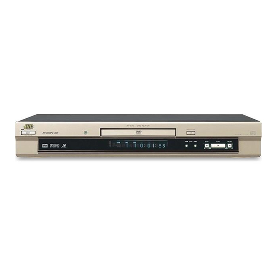
JVC XV-S40BK Service Manual
Hide thumbs
Also See for XV-S40BK:
- Instructions manual (55 pages) ,
- Service manual (50 pages) ,
- Instructions manual (48 pages)
Quick Links
SERVICE MANUAL
XV-S40BK/XV-S42SL
XV-S45GD/XV-S30BK
OPEN
STANDBY/ON
/CLOSE
PLAY
3D
MODE
PHONIC CANCEL
RETURN
1
2
3
4
5
6
7
8
9
10
0
+10
THEATER
ANGLE
SUBTITLE
AUDIO
POSITION
DIGEST
ZOOM
SELECT
ENTER
RM-SXVB40A REMOTE CONTROL
This service manual is a service manual of the
model which changes a part of specification of the
above-mentioned model which has already been
put on the market.
Please refer to the following page for details.
Contents
For this service manual ------------------ 1-2
Safety precautions ------------------------ 1-3
Preventing static electricity ------------- 1-4
Importance admistering
point on the safety ---------- 1-5
Important for laser products ------------ 1-6
DVD VIDEO PLAYER
XV-E100SL
[ MK2 ]
DVD/CD PLAYER
STANDBY
STANDBY ON
DOLBY
D I G I T A L
VIDEO CD
For only Asia
This service manual is printed on 100% recycled paper.
COPYRIGHT
2001 VICTOR COMPANY OF JAPAN, LTD.
OPEN/CLOSE
DVD/VIDEO CD/CD
SKIP
STOP
PLAY
PAUSE
Precautions for service ----------------- 1-7
Disassembly method -------------------- 1-8
Adjustment method ---------------------- 1-17
Troubleshooting -------------------------- 1-21
Description of major ICs ---------------- 1-25
XV-S40BK/XV-S42SL
XV-S45GD/XV-S30BK
XV-E100SL
Area Suffix
(XV-S40BK/XV-S30BK)
J -------------------- U.S.A.
C ----------------- Canada
Area Suffix (XV-S42SL)
C ----------------- Canada
A ---------------- Australia
UG -------- Turkey,Egypt,
South Africa
US ------------ Singapore
UP ------------------ Korea
UW - Brazil,Mexico,Peru
Area Suffix (XV-S45GD)
J -------------------- U.S.A.
Area Suffix (XV-E100SL)
J -------------------- U.S.A.
C ----------------- Canada
US ------------ Singapore
UP ------------------ Korea
UB ----------- Hong Kong
No.A0023
Nov. 2001

Related Manuals for JVC XV-S40BK


Summary of Contents for JVC XV-S40BK
- Page 1 XV-S40BK/XV-S42SL XV-S45GD/XV-S30BK XV-E100SL SERVICE MANUAL DVD VIDEO PLAYER XV-S40BK/XV-S42SL XV-S45GD/XV-S30BK XV-E100SL [ MK2 ] Area Suffix (XV-S40BK/XV-S30BK) J -------------------- U.S.A. OPEN STANDBY/ON /CLOSE C ----------------- Canada PLAY MODE PHONIC CANCEL RETURN Area Suffix (XV-S42SL) THEATER ANGLE SUBTITLE AUDIO POSITION C ----------------- Canada...
- Page 2 XV-S40BK/XV-S42SL/XV-S45GD XV-S30BK/XV-E100SL For this service manual This service manual is a service manual of the model which changes a part of specification of the above-mentioned model which has already been put on the market. < When the label in figure is pasted in the main body >...
- Page 3 XV-S40BK/XV-S42SL/XV-S45GD XV-S30BK/XV-E100SL 1. This design of this product contains special hardware and many circuits and components specially for safety purposes. For continued protection, no changes should be made to the original design unless authorized in writing by the manufacturer. Replacement parts must be identical to those used in the original circuits. Services should be performed by qualified personnel only.
- Page 4 XV-S40BK/XV-S42SL/XV-S45GD XV-S30BK/XV-E100SL Preventing static electricity Electrostatic discharge (ESD), which occurs when static electricity stored in the body, fabric, etc. is discharged, can destroy the laser diode in the traverse unit (optical pickup). Take care to prevent this when performing repairs.
- Page 5 XV-S40BK/XV-S42SL/XV-S45GD XV-S30BK/XV-E100SL Importance admistering point on the safety < For only version J,C > J703 J604 J602 C904 C1701 J691 S691 J601 B7029 L710 B7030 B7034 B7309 D702 B7026 Q754 C694 D901 B7031 C738 B7308 C737 B7307 B7124 B7306 R616...
- Page 6 XV-S40BK/XV-S42SL/XV-S45GD XV-S30BK/XV-E100SL Important for laser products < For only europe > 1.CLASS 1 LASER PRODUCT 5.CAUTION : If safety switches malfunction, the laser is able to function. 2.DANGER : Invisible laser radiation when open and inter 6.CAUTION : Use of controls, adjustments or performance of lock failed or defeated.
- Page 7 XV-S40BK/XV-S42SL/XV-S45GD XV-S30BK/XV-E100SL Precautions for Service Handling of Traverse Unit and Laser Pickup 1. Do not touch any peripheral element of the pickup or the actuator. 2. The traverse unit and the pickup are precision devices and therefore must not be subjected to strong shock.
-
Page 8
XV-S40BK/XV-S42SL/XV-S45GD XV-S30BK/XV-E100SL Disassembly method There is a part different from the photograph according to the model and the destination though explains this disassembly method by using XV-E100SL.
Removing the top cover (see Fig.1) A x 2 1.Remove the two screws A attaching the top cover on both sides of the body. - Page 9 XV-S40BK/XV-S42SL/XV-S45GD XV-S30BK/XV-E100SL Removing the rear panel (see Fig.5) *Prior to performing the following procedure, remove Rear panel the top cover. 1.Remove the eight screws D attaching the rear panel on the back of the body. * As for the screw D, the number and the position are different according to the destination.
-
Page 10
XV-S40BK/XV-S42SL/XV-S45GD XV-S30BK/XV-E100SL
Removing the clamper assembly Joint a Joint a (See Fig.1) Remove the four screws A attaching the clamper assembly. Move the clamper in the direction of the arrow to release the two joints a on both sides. - Page 11 XV-S40BK/XV-S42SL/XV-S45GD XV-S30BK/XV-E100SL Removing the traverse mechanism assembly (See Fig.4 and 5) Prior to performing the following procedure, remove the clamper assembly and the tray. Traverse mechanism Remove the four screws B attaching the traverse assembly mechanism assembly. ATTENTION: Before reattaching the traverse...
- Page 12 XV-S40BK/XV-S42SL/XV-S45GD XV-S30BK/XV-E100SL Removing the motor assembly (See Fig.8 and 9) Belt Prior to performing the following procedure, remove the clamper assembly, the tray, the traverse mechanism assembly and the elevator. Remove the belt from the pulley. Remove the screw C attaching the motor assembly.
- Page 13 XV-S40BK/XV-S42SL/XV-S45GD XV-S30BK/XV-E100SL Pulley gear Idle gear Pulley gear bracket Pulley gear Idle gear Pulley gear bracket Tads h Pulley gear Motor assembly Fig.10 Slide cam Removing the Idle gear / pulley gear / middle gear / slide cam (See Fig.10 to 12)
-
Page 14
XV-S40BK/XV-S42SL/XV-S45GD XV-S30BK/XV-E100SL Feed motor assembly
Removing the feed motor assembly (See Fig.13) Unsolder the two soldering j on the spindle motor board. Remove the two screws F attaching the feed motor assembly. Pickup Notch k Soldering j... - Page 15 XV-S40BK/XV-S42SL/XV-S45GD XV-S30BK/XV-E100SL Removing the pickup (See Fig.16 and 17) Pickup Joint n Remove the screw I attaching the T spring (S) and Shaft holder the shaft holder. Remove also the plate. ATTENTION: When reattaching, make sure that the T spring (S) presses the shaft.
- Page 16 XV-S40BK/XV-S42SL/XV-S45GD XV-S30BK/XV-E100SL Spindle motor Removing the spindle motor assembly (See Fig.19 to 21) Remove the three screws L attaching the spindle motor on the bottom of the mechanism base. ATTENTION: When reattaching, pass the card wire extending from the spindle motor board through the notch of the spindle base.
- Page 17 XV-S40BK/XV-S42SL/XV-S45GD XV-S30BK/XV-E100SL Adjustment method (1) Initialization method If microprocessor (IC401,IC402,IC403) or pick-up is replaces, initialize the DVD player in the following matter 1)Take out the disc and close the tray. 2)Unplug the power plug. 3)Insert power plug into outlet while pressing both "PLAY" button and "OPEN/CLOSE" button.
- Page 18 XV-S40BK/XV-S42SL/XV-S45GD XV-S30BK/XV-E100SL For Jitter value The jitter value is displayed on the FL display referring to the previous page. The jitter value is displayed by the hexadecimal number. In the following cases, please "Flap adjustment of the pick-up guide shaft" referring to the following page.
-
Page 19
XV-S40BK/XV-S42SL/XV-S45GD XV-S30BK/XV-E100SL (3) Flap adjustment of the pick-up guide shaft
* Hex wrench for adjustment Off-the-shelf (1.3mm) * Test disc VT-501 or VT-502 * Stud (four pieces set) Parts No. : JIGXVS40 (One is not used though there are four. ) * Assistance board and extension cord Parts No. -
Page 20
XV-S40BK/XV-S42SL/XV-S45GD XV-S30BK/XV-E100SL
1.The mechanism assembly is made in the state from the main body from which is detached referring to the disassembly method. 2.Three studs are installed in the mechanism assembly respectively. 3.The servo control board is removed from the mechanism assembly, and puts into the state set up as shown in figure. - Page 21 XV-S40BK/XV-S42SL/XV-S45GD XV-S30BK/XV-E100SL Troubleshooting Servo volume Press OPEN /CLOSE key Is tray Confirmation of tray drive circuit operation and circuit in surrounding correct? Is the traverse moving See "(3) Traverse movement error" along the innermost in "Check points for individual errors"...
- Page 22 XV-S40BK/XV-S42SL/XV-S45GD XV-S30BK/XV-E100SL Check points for each error (1) Spindle start error 1.Defective spindle motor *Are there several ohms resistance between each pin of CN201 "5-6","6-7","5-7"? (The power supply is turned off and measured.) *Is the sign wave of about 100mVp-p in the voltage had from each terminal? [ CN201"9"(H1-),"10"(H1+),"11"(H2-),"12"(H2+),"13"(H3-),"14"(H3+) ]...
- Page 23 XV-S40BK/XV-S42SL/XV-S45GD XV-S30BK/XV-E100SL (3) Traverse movement NG 1.Defective traverse driver *Has the voltage come between terminal of CN101 "1" and "2" ? 2.Defective BTL driver (IC201) *Has the motor drive voltage gone out to IC201"17" or "18"? 3.Has the control signal come from servo IC or the microcomputer? *Is it "H"...
- Page 24 XV-S40BK/XV-S42SL/XV-S45GD XV-S30BK/XV-E100SL (9) Neither picture nor sound is output 1.It is not possible to search *Has the tracking been turned on? *To "(5) Tracking ON NG" in "Check points for each error" when the tracking is not normal. *Is the feed operation normal? To "(3) traverse movement NG"...
- Page 25 XV-S40BK/XV-S42SL/XV-S45GD XV-S30BK/XV-E100SL Description of major ICs AN8703FH-V (IC101) : Frontend processor 1.Pin layout 2.Pin function Symbol Description Symbol Description Pin No. Pin No. LPC1 Laser input terminal (DVD) RFDIFO Non connect LPC01 Laser drive signal output terminal (DVD) RFOUT Connect to TP103...
- Page 26 XV-S40BK/XV-S42SL/XV-S45GD XV-S30BK/XV-E100SL BA5983FM-X (IC201) : 4CH Driver 1.Block diagram STAND BY Level Shift Level Shift Level Shift Level Shift STAND BY CH1/2/3 2.Pin function Pin No. Symbol Description Pin No. Symbol Description Input for Bias-amplifier VO4(+) Non inverted output of CH4...
- Page 27 XV-S40BK/XV-S42SL/XV-S45GD XV-S30BK/XV-E100SL BA6664FM-X (IC251) : 3Phase Motor Driver 1.Pin layout 2.Block diagram DRIVER GAIN SWITCH GAIN CONTROL CURRENT SENSE AMP HALL AMP TOROUE SERVO SENSE AMP SIGNAL Hall 1 Hall 2 SHORT BRAKE CK Q Hall 3 BRAKE MODE Hall Bias...
- Page 28 XV-S40BK/XV-S42SL/XV-S45GD XV-S30BK/XV-E100SL 3.Pin function BA6664FM-X Symbol Description Pin No. Non connect Output 3 for spindle motor Non connect Output 2 for spindle motor Non connect Non connect Output 1 for spindle motor Connect to ground Positive input for hall input AMP 1...
- Page 29 XV-S40BK/XV-S42SL/XV-S45GD XV-S30BK/XV-E100SL K4S641632E-TC75 (IC504) :CMOS SDRAM 1.Pin layout 2.Block diagram Data input register LDQM Bank select 1M x 16 1M x 16 1M x 16 1M x 16 Column decoder Latency & Burst length LCKE Programming register LDQM LRAS LCBR...
- Page 30 XV-S40BK/XV-S42SL/XV-S45GD XV-S30BK/XV-E100SL MN101C35DGN(IC701):System controller Pin function Symbol Description Pin No. DAC control data DDATA DAC control clock DCLK DAC control chip select DACOCS Not use DI/DO/CS/SK Power supply +B 5V Oscillation terminal 8MHz OSC2 Oscillation terminal 8MHz OSC1 Connect to ground...
- Page 31 XV-S40BK/XV-S42SL/XV-S45GD XV-S30BK/XV-E100SL MN102L62GGY (IC401) : Unit CPU Pin function Symbol Function Symbol Function Pin No. Pin No. Micon wait signal input Connect to TP406 WAIT Read enable Connect to TP405 Spindle muting output to IC251 Connect to TP404 SPMUTE P85/TM5IO...
- Page 32 XV-S40BK/XV-S42SL/XV-S45GD XV-S30BK/XV-E100SL MN103S28EGA (IC301) : Super optical disc controller 1.Terminal layout 2.Block diagram DVD-ROM Host I/F Analog Formatter MPEG I/F CD-PRE ATAPI High speed IO bus Instruction Servo I/O CGEN memory (core 1 I/O) (40KB) 32 bit CPU core 2Mbit...
- Page 33 XV-S40BK/XV-S42SL/XV-S45GD XV-S30BK/XV-E100SL 3.Pin function (MN103S28EGA : 2/4) Symbol Description Pin No. Read signal input from system controller System control data 37~44 CPUDT7~0 Non connect CLKOUT1 Test mode switch signal MMOD System reset NRST Master terminal polarity switch input MSTPOL Non connect...
- Page 34 XV-S40BK/XV-S42SL/XV-S45GD XV-S30BK/XV-E100SL 3.Pin function (MN103S28EGA : 3/4) Symbol Description Pin No. PLFLT1 Connect to capacitor 1 for PLL AVSS Connect to ground for analog circuit Connect to resistor for VREF reference current source VREFH Reference voltage input (2.2V) PLPG Non connect VHALF Reference voltage input (1.65V)
- Page 35 XV-S40BK/XV-S42SL/XV-S45GD XV-S30BK/XV-E100SL 3.Pin function (MN103S28EGA : 4/4) Symbol Description Pin No. Connect to ground VDD3 Power supply terminal for I/O (3.3V) HDD1 ATAPI host data 1 HDD13 ATAPI host data 13 HDD2 ATAPI host data 2 HDD12 ATAPI host data 12...
- Page 36 XV-S40BK/XV-S42SL/XV-S45GD XV-S30BK/XV-E100SL CY24203SC-X (IC571) : MPEG/Audio clock generator with VCXO 1.Pin layout 2.Pin function Pin No. Symbol Description XOUT Reference crystal input Power supply VCXO 13.5M VCXO Input analog control for VCXO 16.9344M Connect to ground 16.9344M 16.9344 MHz clock output 13.5...
- Page 37 XV-S40BK/XV-S42SL/XV-S45GD XV-S30BK/XV-E100SL MN35505-X (IC703) : DAC 1.Terminal layout LRCK DVDD1 DVDD2 VCOF DVSS2 XOUT DVSS1 OUT1C OUT2C AVDD1 AVDD2 OUT1D OUT2D AVSS1 AVSS2 2. Pin function Pin No. Symbol Description Control signal for DAC Digital data input LRCK L and R clock for DAC...
- Page 38 XV-S40BK/XV-S42SL/XV-S45GD XV-S30BK/XV-E100SL MR27V1602E1UTPX (IC402) :P2 ROM of 1,048,576word x 16 bit / 2,097,152 word x 8 bit 1.Pin layout 2.Block diagram x 8 / x 16 Output select BYTE Memory Cell Matrix 1,048,576 x 16-Bit or 2,097,152 x 8-Bit Multiplexer...
- Page 39 XV-S40BK/XV-S42SL/XV-S45GD XV-S30BK/XV-E100SL NJM4580M-X (IC741,IC751) : Dual OP amplifier Block diagram B OUT B -IN B +IN A OUT A -IN A +IN NJM78M05FA (IC953) : Regulator 1.Terminal layout 2.Block diagram INPUT 1.INPUT 2.GND 3.OUTPUT OUTPUT PQ05RD21 (IC951) : Regulator 1.Terminal layout 2.Block diagram...
- Page 40 XV-S40BK/XV-S42SL/XV-S45GD XV-S30BK/XV-E100SL S-93C66AFJ-X (IC451) : EEPROM 1.Pin layout 2.Pin function Pin No. Symbol Description Non connect Power supply terminal Chip select input Serial clock input Serial data input Serial data output Connect to ground Non connect 1.Block diagram Memory Address...
- Page 41 XV-S40BK/XV-S42SL/XV-S45GD XV-S30BK/XV-E100SL ZIVA-4.1-PA2(IC501):Back end - Digital decoder 1.Terminal layout 2.Pin function (1/5) Pin No. Symbol Description Read strobe input Read/write strobe input Power supply terminal 3.3V Transfer not complete / data acknowledge. WAIT Active LOW to indicate host initiated transfer is complete.
- Page 42 XV-S40BK/XV-S42SL/XV-S45GD XV-S30BK/XV-E100SL 2.Pin function (ZIVA-4.1-PA2 : 2/5) Pin No. Symbol Description Connect to ground Non connect Non connect Non connect Non connect Non connect Programmable I/O terminal PIO0 Connect to ground Power supply terminal 3.3V Programmable I/O terminal PIO1 Programmable I/O terminal...
- Page 43 XV-S40BK/XV-S42SL/XV-S45GD XV-S30BK/XV-E100SL 2.Pin function (ZIVA-4.1-PA2 : 3/5) Pin No. Symbol Description SDRAM address MADDR6 SDRAM address MADDR5 Power supply terminal 2.5V Connect to ground SDRAM address MADDR4 SDRAM write enable Active LOW SDRAM column address SD-CAS Power supply terminal 3.3V...
- Page 44 XV-S40BK/XV-S42SL/XV-S45GD XV-S30BK/XV-E100SL 2.Pin function (ZIVA-4.1-PA2 : 4/5) Pin No. Symbol Description Connect to ground Non connect Connect to ground for analog video DAC VSS_DAC VSS_VIDEO Connect to ground for analog video CVBS DAC video output format : CVBS. Macrovision encoded...
- Page 45 XV-S40BK/XV-S42SL/XV-S45GD XV-S30BK/XV-E100SL 2.Pin function (ZIVA-4.1-PA2 : 5/5) Pin No. Symbol Description DVD parallel compressed data from DVD DSP. or CD-G clock indicating DVD-DATA7/CDG-SCLK sub code data clock input or output In synchronous mode, bitstream data acknowledge. Asserted when DVD VDACK data is valid.Polarity is programmable...
- Page 46 XV-S40BK/XV-S42SL/XV-S45GD XV-S30BK/XV-E100SL In regard with component parts appearing on the silk-screen printed side (parts side) of the PWB diagrams, the parts that are printed over with black such as the resistor ( diode ( ) and ICP ( ) or identified by the " " mark nearby are critical for safety.
- Page 47 XV-S40BK/XV-S42SL/XV-S45GD XV-S30BK/XV-E100SL Block diagrams DVD Servo control & AV decoder section (SHEET 5,6) CN502 CN503 WAITDEC DRVMUTE CN101 CN201 CN202...
- Page 48 XV-S40BK/XV-S42SL/XV-S45GD XV-S30BK/XV-E100SL System control & audio output section (SHEET 4) RESET J702 IC702 AIN0 AIN2 TO FW801 AV COMPULINK AV Compulink SHEET 1 except XV-S30BK RESET Q709 AVCO AVCI except XV-S30BK POWERSW STANDBYIND REMO SYSTEM CONTROLLER X701(8MHz) TO FW802 IC701...
- Page 49 XV-S40BK/XV-S42SL/XV-S45GD XV-S30BK/XV-E100SL DC Regulator section (SHEET 2) CN961...
- Page 50 XV-S40BK/XV-S42SL/XV-S45GD XV-S30BK/XV-E100SL Audio & Video signal output section (SHEET 3) < For except Europe > C/R/V J601 L601, L602 Q601 Y/B/U COMPONENT Q611 L611, L612 VIDEO OUT Q621 CVBS/Y/G L621, L622 S-VIDEO OUT CVBS COMPOSITE Q631 TO SHEET 4 L631, L632...
- Page 51 TO CN702 SHEET 4 TO CN703 SHEET 4 FW801 FW802 QUM123-11DGZ4 QUM125-09DGZ4 S801 IC801 GP1U271X QSW0651-001Z R801 S821 S831 D801 SLR-342VC-T C801 S832 C802 47/10 S833 S834 S835 TO SHEET 2 S1-S24.1G-13G TO SHEET 4 C821 4.7/50 XV-S40BK/S42SL/S45GD/S30BK/E100SL (MK2) SHEET 1...
- Page 52 2SC2060/QR/-T D956 F1T4-T2 C982 C984 560/25 220/25 100/6.3 100/6.3 C987 C989 100/6.3 180/25 100/25 D957 F1T4-T2 L959 D.GND C957 100p Parts are safety assurance parts. When replacing those parts make sure to use the specified one. XV-S40BK/S42SL/S45GD/S30BK/E100SL (MK2) SHEET 2...
- Page 53 TO SHEET 4 R685 R688 Q692 R1731 R696 KRC102S-X Q691 Audio signal KRC102S-X R1732 +12V Video signal NTSC/PAL R695 C695 RGBSEL 470/6.3 R694 C694 470/6.3 S691 QSW0454-001 Q696 KRA102S-X R681 C691 R699 100p R682 Q697 KRC102S-X XV-S40BK/S42SL/S45GD/S30BK/E100SL (MK2) SHEET 3...
- Page 54 C729 C1702 C1701 47/25 R1722 47/25 R704 IC704 TC7S08F-W R1730 S1-S24.1G-13G J703 R705 K706 QNZ0487-001 SHEET 1 NQR0227-004X P.ON R706 K705 C707 C736 100K D1.8V R1716 NQR0227-004X 100/6.3 SHEET 2 -12V P.MUTE Audio signal XV-S40BK/S42SL/S45GD/S30BK/E100SL (MK2) SHEET 4 Video signal...
- Page 55 XV-S40BK/XV-S42SL/XV-S45GD XV-S40BK/XV-S42SL/XV-S45GD XV-S30BK/XV-E100SL XV-S30BK/XV-E100SL DVD Servo control section K301 K302 K303 D1.8V K304 R341 5.6K DGND CN101 QGF0501F2-30X ODCIRQ2 R318 C144 ODCIRQ 0.01/16 R319 T2CD C113 TP309 C145 22/6.3 F2CD C347 TP308 0.1/16 ADSCIRQ TP307 T1CD C141 TP306 0.1/16 HDTYPE C310 0.1/16...
- Page 56 CPUD0 CPUD7 DGND NQR0007-002X NQR0007-002X CPUD1 CPUD6 DA_BCK K562 NQR0007-002X CN503 CPUD2 CPUD5 QGB2027L1-26X CPUD4 CPUD3 C411 0.1/16 DGND IC402 DGND MR27V1602ETP K402 NQR0007-002X DGND Digital data signal Audio signal Video signal TO SHEET 5 XV-S40BK/S42SL/S45GD/S30BK/E100SL (MK2) SHEET 6 2-11...
- Page 57 XV-S40BK/XV-S42SL/XV-S45GD XV-S40BK/XV-S42SL/XV-S45GD XV-S30BK/XV-E100SL XV-S30BK/XV-E100SL Printed circuit boards Main board R663 J702 J601 J604 S691 P901 Q697 C691 R697 C736 R778 C685 C1701 R1721 K708 R768 R777 R767 R705 C904 R694 R685 C1704 R706 C694 R681 R665 L710 Q754 C686 Q692...
- Page 58 XV-S40BK/XV-S42SL/XV-S45GD XV-S30BK/XV-E100SL DVD Servo control board (Forward side) (Reverse side) C203 R222 TP80 R210 TP82 R212 TP84 CN502 C252 C216 IC251 R221 TP81 TP83 TP85 C333 TP86 C201 TP87 C304 R337 R336 R220 K301 C308 C329 C321 C259 C258 C257...
- Page 59 XV-S40BK/XV-S42SL/XV-S45GD XV-S30BK/XV-E100SL Loading motor board 2-14...
- Page 60 XV-S40BK/XV-S42SL/XV-S45GD XV-S30BK/XV-E100SL PARTS LIST [XV-S40BK/XV-S42SL/XV-S45GD [XV-S30BK/XV-E100SL] * All printed circuit boards and its assemblies are not available as service parts. Area Suffix (XV-S30BK/XV-S40BK) C ---- Canada J ----- U.S.A. Area Suffix (XV-S42SL) A ------ Australia C ------ Canada UG --- Turkey, South Africa, Egypt...
- Page 61 XV-S40BK/XV-S42SL/XV-S45GD XV-S30BK/XV-E100SL Exploded view of general assembly and parts list Block No. M 28 BACK SIDE Grease UD-24H2R 27 BACK SIDE...
- Page 62 13 =XV-E100SL ver. C 2 =XV-S30BK ver. J 6 =XV-S42SL ver. C 10 =XV-S42SL ver. UW 14 =XV-E100SL ver. UB 3 =XV-S40BK ver. C 7 =XV-S42SL ver. UG 11 =XV-S45GD ver. J 15 =XV-E100SL ver. UP 4 =XV-S40BK ver. J 8 =XV-S42SL ver.
- Page 63 13 =XV-E100SL ver. C 2 =XV-S30BK ver. J 6 =XV-S42SL ver. C 10 =XV-S42SL ver. UW 14 =XV-E100SL ver. UB 3 =XV-S40BK ver. C 7 =XV-S42SL ver. UG 11 =XV-S45GD ver. J 15 =XV-E100SL ver. UP 4 =XV-S40BK ver. J 8 =XV-S42SL ver.
- Page 64 XV-S40BK/XV-S42SL/XV-S45GD XV-S30BK/XV-E100SL DVD Traverse mechanism assembly and parts list Block No. M Grease EBS0006-013B PG-641 CFD-4007ZY2 12.0mm 0.2mm 65.2mm...
- Page 65 XV-S40BK/XV-S42SL/XV-S45GD XV-S30BK/XV-E100SL Parts list (DVD Traverse mechanism assembly) Block No. M2MM Item Parts number Parts name Q'ty Description Area LE20520-002A MECHA BASE LE20516-001A SPINDLE BASE QYSDST2605M TAPPING SCREW LE30909-001A HOLDER QAR0165-001 FEED MOTOR LV41510-001A FEED GEAR QYSPSPU2040M SCREW LV41512-001A FEED GEAR...
- Page 66 XV-S40BK/XV-S42SL/XV-S45GD XV-S30BK/XV-E100SL DVD Loading mechanism assembly and parts list Block No. M Grease UD-24H2 EM-30L CFD-4007ZY2...
- Page 67 XV-S40BK/XV-S42SL/XV-S45GD XV-S30BK/XV-E100SL Parts list (DVD Loading mechanism assembly) Block No. M3MM Item Parts number Parts name Q'ty Description Area LV10454-007A LOADING BASE QAR0164-001 MOTOR LV42087-001A MOTOR PULLEY QYSPSPU1730Z SCREW VKZ4777-003 MINI SCREW LV42209-001A BELT LV42084-002A PULLEYGEAR LV42085-002A MIDDLE GEAR LV42086-001A...
- Page 68 13 =XV-E100SL ver. C 2 =XV-S30BK ver. J 6 =XV-S42SL ver. C 10 =XV-S42SL ver. UW 14 =XV-E100SL ver. UB 3 =XV-S40BK ver. C 7 =XV-S42SL ver. UG 11 =XV-S45GD ver. J 15 =XV-E100SL ver. UP 4 =XV-S40BK ver. J 8 =XV-S42SL ver.
- Page 69 13 =XV-E100SL ver. C 2 =XV-S30BK ver. J 6 =XV-S42SL ver. C 10 =XV-S42SL ver. UW 14 =XV-E100SL ver. UB 3 =XV-S40BK ver. C 7 =XV-S42SL ver. UG 11 =XV-S45GD ver. J 15 =XV-E100SL ver. UP 4 =XV-S40BK ver. J 8 =XV-S42SL ver.
- Page 70 13 =XV-E100SL ver. C 2 =XV-S30BK ver. J 6 =XV-S42SL ver. C 10 =XV-S42SL ver. UW 14 =XV-E100SL ver. UB 3 =XV-S40BK ver. C 7 =XV-S42SL ver. UG 11 =XV-S45GD ver. J 15 =XV-E100SL ver. UP 4 =XV-S40BK ver. J 8 =XV-S42SL ver.
- Page 71 XV-S40BK/XV-S42SL/XV-S45GD XV-S30BK/XV-E100SL Electrical parts list (Main board) Block No. 01 Item Parts number Parts name Remarks Area R1725 NRSA63J-102X MG RESISTOR R1727 NRSA63J-0R0X MG RESISTOR R1728 NRSA63J-222X MG RESISTOR R1729 NRSA63J-222X MG RESISTOR R1730 QRE141J-103Y C RESISTOR 10K 5% 1/4W...
- Page 72 NCB31CK-104X C CAPACITOR Explanation of area column 1 =XV-S30BK ver. C 6 =XV-S42SL ver. C 2 =XV-S30BK ver. J 11 =XV-S45GD ver. J 3 =XV-S40BK ver. C 12 =XV-E100SL ver. J 4 =XV-S40BK ver. J 13 =XV-E100SL ver. C 3-13...
- Page 73 13 =XV-E100SL ver. C 2 =XV-S30BK ver. J 6 =XV-S42SL ver. C 10 =XV-S42SL ver. UW 14 =XV-E100SL ver. UB 3 =XV-S40BK ver. C 7 =XV-S42SL ver. UG 11 =XV-S45GD ver. J 15 =XV-E100SL ver. UP 4 =XV-S40BK ver. J 8 =XV-S42SL ver.
- Page 74 XV-S40BK/XV-S42SL/XV-S45GD XV-S30BK/XV-E100SL Block No. 02 Electrical parts list (Servo control board) Item Remarks Item Remarks Parts number Parts name Area Parts number Parts name Area R 214 NRSA63J-103X MG RESISTOR R 502 NRSA63J-472X MG RESISTOR R 504 NRSA63J-330X MG RESISTOR...
- Page 75 XV-S40BK/XV-S42SL/XV-S45GD XV-S30BK/XV-E100SL Packing materials and accessories parts list Block No. M4MM Block No. M5MM A3 A4 Accessories Except XV-S42SLA XV-S42SLA XV-E100SLUB XV-E100SLUB only 3-16...
- Page 76 13 =XV-E100SL ver. C 2 =XV-S30BK ver. J 6 =XV-S42SL ver. C 10 =XV-S42SL ver. UW 14 =XV-E100SL ver. UB 3 =XV-S40BK ver. C 7 =XV-S42SL ver. UG 11 =XV-S45GD ver. J 15 =XV-E100SL ver. UP 4 =XV-S40BK ver. J 8 =XV-S42SL ver.
- Page 77 QMPP060-183-JD POWER CORD QMP25D0-183 POWER CORD QPC02503510P POLY BAG 5,14 BT-52004-2 WARRANTY CARD 1,3,6,13 BT-56001-2 WARRANTY CARD BT-20071B JVC CENTER LIST 1,3,6,13 BT-56002-2 SVC CENTER LIST QAM0328-001 AV CORD 3P RM-SXVS40A REMOCON UNIT 1,2,3,4 RM-SXVS42U REMOCON UNIT 5,7,8,9,10,14,15,16 RM-SXVS42A REMOCON UNIT...