
Related Manuals for Dell OptiPlex XE4 Tower


Summary of Contents for Dell OptiPlex XE4 Tower
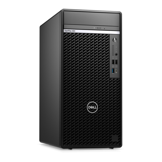
- Page 1 OptiPlex XE4 Tower Service Manual Regulatory Model: D31M Regulatory Type: D31M001 Mar 2022 Rev. A00...
- Page 2 A WARNING indicates a potential for property damage, personal injury, or death. © 2022 Dell Inc. or its subsidiaries. All rights reserved. Dell, EMC, and other trademarks are trademarks of Dell Inc. or its subsidiaries. Other trademarks may be trademarks of their respective owners.
-
Page 3: Table Of Contents
After working inside your computer........................10 BitLocker..................................10 Chapter 2: Removing and installing components................11 Recommended tools................................11 Screw list....................................11 Major components of OptiPlex XE4 Tower......................... 12 Side cover.................................... 13 Removing the side cover............................13 Installing the side cover.............................. 14 Front bezel ..................................16 Removing the front bezel............................16... - Page 4 Removing the memory module..........................35 Installing the memory module...........................36 Expansion card................................... 37 Removing the graphics card............................. 37 Installing the graphics card............................38 Removing optional SMA module..........................39 Installing optional SMA module..........................40 Removing optional powered add-in-card.......................42 Installing optional powered add-in-card.........................44 Graphical processing unit..............................46 Removing the powered GPU............................
- Page 5 Deleting or changing an existing system setup password................117 Clearing CMOS settings..............................118 Clearing BIOS (System Setup) and System passwords..................118 Chapter 5: Troubleshooting......................119 Dell SupportAssist Pre-boot System Performance Check diagnostics...............119 Running the SupportAssist Pre-Boot System Performance Check............... 119 Power-Supply Unit Built-in Self-Test .........................119 Diagnostic LED behavior..............................120 Recovering the operating system..........................121...
- Page 6 Chapter 6: Getting help and contacting Dell................123 Contents...
-
Page 7: Chapter 1: Working Inside Your Computer
You should only perform troubleshooting and repairs as authorized or directed by the Dell technical assistance team. Damage due to servicing that is not authorized by Dell is not covered by your warranty. See the safety instructions that is shipped with the product or at www.dell.com/regulatory_compliance. -
Page 8: Safety Precautions
ESD protection is an increasing concern. Due to the increased density of semiconductors used in recent Dell products, the sensitivity to static damage is now higher than in previous Dell products. For this reason, some previously approved methods of handling parts are no longer applicable. -
Page 9: Esd Field Service Kit
It is recommended that all field service technicians use the traditional wired ESD grounding wrist strap and protective anti-static mat at all times when servicing Dell products. In addition, it is critical that technicians keep sensitive parts separate from all insulator parts while performing service and that they use anti-static bags for transporting sensitive components. -
Page 10: Transporting Sensitive Components
Transporting sensitive components When transporting ESD sensitive components such as replacement parts or parts to be returned to Dell, it is critical to place these parts in anti-static bags for safe transport. Lifting equipment Adhere to the following guidelines when lifting heavy weight equipment: CAUTION: Do not lift greater than 50 pounds. -
Page 11: Chapter 2: Removing And Installing Components
Removing and installing components NOTE: The images in this document may differ from your computer depending on the configuration you ordered. Recommended tools The procedures in this document may require the following tools: ● Phillips screwdriver #0 ● Phillips screwdriver #1 ●... -
Page 12: Major Components Of Optiplex Xe4 Tower
Table 1. Screw list (continued) Component Screw type Quantity Screw image Major components of OptiPlex XE4 Tower The following image shows the major components of OptiPlex XE4 Tower. 1. Side cover 2. 3.5-inch hard-disk drive 3. Slim ODD 4. Heat sink 5. WLAN card 6. -
Page 13: Side Cover
17. 2.5-inch hard-disk drive NOTE: Dell provides a list of components and their part numbers for the original system configuration purchased. These parts are available according to warranty coverages purchased by the customer. Contact your Dell sales representative for purchase options. -
Page 14: Installing The Side Cover
Steps 1. Slide the release latch to release the side cover from the computer. 2. Slide the side cover towards the rear of the computer and lift the side cover away from the chassis. Installing the side cover Prerequisites If you are replacing a component, remove the existing component before performing the installation procedure. About this task The following image indicates the location of the side cover and provides a visual representation of the installation procedure. - Page 15 Steps 1. Align the tabs on the side cover with the slots on the chassis. 2. Slide the side cover towards the front of the computer to install it. 3. The release latch automatically locks the side cover to the chassis. Next steps 1.
-
Page 16: Front Bezel
Front bezel Removing the front bezel Prerequisites 1. Follow the procedure in before working inside your computer. 2. Remove the side cover. About this task The following images indicate the location of the front bezel and provide a visual representation of the removal procedure. Steps 1. -
Page 17: Hard-Drive Assembly
About this task The following image indicates the location of the front bezel and provides a visual representation of the installation procedure. Steps 1. Position the front bezel to align the tabs on the bezel with the slots on the chassis. 2. -
Page 18: Removing The Secondary 2.5-Inch Hard Drive Assembly
Steps 1. Disconnect the hard drive data and power cables from the connectors on the 2.5-inch hard drive module. 2. Press the release tabs on both the sides of the hard drive bracket to release it from the slots on the computer chassis. 3. -
Page 19: Removing The 2.5-Inch Hard Drive Bracket
Steps 1. Disconnect the power cable and the black hard drive data cable from the connectors on the 2.5-inch hard drive. NOTE: For secondary 2.5-inch hard drive, the other end of the black hard drive data cable is connected to the SATA1 and SATA2 connectors on the system board. -
Page 20: Installing The 2.5-Inch Hard Drive Bracket
About this task The following images indicate the location of the hard drive bracket and provide a visual representation of the removal procedure. Steps 1. Pull one side of the hard drive bracket to disengage the pins on the bracket from the slots on the drive. 2. -
Page 21: Installing The Secondary 2.5-Inch Hard Drive Assembly
Steps 1. Align the hard drive to the side of the hard drive bracket. 2. Pull the other end of the hard drive bracket to insert the pins on the bracket into the slot on the hard drive. 3. Insert the hard drive into the hard drive bracket until it clicks into place. Next steps 1. -
Page 22: Installing The Primary 2.5-Inch Hard Drive Assembly
Steps 1. Insert the hard drive assembly into the slot on the computer until it clicks into place. 2. For 2.5-inch hard drive set as secondary, connect the black hard drive data cable and power cable to the connectors on the 2.5-inch hard drive. -
Page 23: 3.5 In. Hard-Drive Assembly
Steps 1. Insert the hard drive assembly into the slot on the computer until it clicks into place. 2. Connect the hard drive data and power cables to the connectors on the 2.5-inch hard drive module. Next steps 1. Install the 2.5-inch primary hard drive 2.5-inch secondary hard drive. -
Page 24: Removing The 3.5-Inch Hard Drive Bracket
About this task The following images indicate the location of the 3.5-inch hard drive assembly and provide a visual representation of the removal procedure. Steps 1. Disconnect the data and power cables from the 3.5-inch hard drive module. 2. Push the securing tab to release the hard drive assembly from the chassis. 3. -
Page 25: Installing The 3.5-Inch Hard Drive Bracket
About this task The following image indicates the location of the 3.5-inch hard drive bracket and provides a visual representation of the removal procedure. Steps 1. Pry one side of the hard drive bracket edge to release the tabs on the bracket from the slots on the hard drive. 2. -
Page 26: Installing The 3.5-Inch Hard Drive Assembly
Steps 1. Align the tabs on the bracket with the slots on the hard drive and place the hard drive into the hard drive bracket. 2. Snap the hard drive into the hard drive bracket. Next steps 1. Install the 3.5-inch hard drive assembly. - Page 27 Steps 1. Slide to insert the 3.5-inch hard drive assembly into the hard drive slot. 2. Replace the EMI shield on the chassis. 3. Align the hard drive assembly with the tabs on the chassis. 4. Route the power cable and the data cable through the routing guides on the hard drive assembly and connect the cables to the hard drive.
-
Page 28: Solid-State Drive
Solid-state drive Removing the M.2 2230 PCIe solid-state drive Prerequisites 1. Follow the procedure in before working inside your computer. 2. Remove the side cover. About this task The following images indicate the location of the solid-state drive and provide a visual representation of the removal procedure. Steps 1. -
Page 29: Removing The M.2 2280 Pcie Solid-State Drive
Steps 1. Align the notch on the solid-state drive with the tab on the solid-state drive connector. 2. Insert the solid-state drive at a 45-degree angle into the connector on the system board. 3. Replace the screw (M2x3.5) to secure the M.2 2230 solid-state drive to the system board. Next steps 1. -
Page 30: Installing The M.2 2280 Pcie Solid-State Drive
Steps 1. Remove the screw (M2x3.5) that secures the solid-state drive to the system board. 2. Slide at an angle to lift and remove the solid-state drive from its connector on the system board. NOTE: Repeat the above procedure for removing the other solid-state drive. Installing the M.2 2280 PCIe solid-state drive Prerequisites If you are replacing a component, remove the existing component before performing the installation procedure. -
Page 31: Wlan Card
Steps 1. Align the notch on the solid-state drive with the tab on the solid-state drive connector. 2. Insert the solid-state drive at a 45-degree angle into the connector on the system board. 3. Replace the screw (M2x3.5) to secure the M.2 2280 solid-state drive to the connector on the system board. NOTE: Repeat the above procedure for installing the other solid-state drive. -
Page 32: Installing The Wlan Card
Steps 1. Remove the (M2x3.5) screw that secures the WLAN card to the system board. 2. Lift the WLAN card bracket away from the WLAN card. 3. Disconnect the antenna cables from the WLAN card. 4. Slide and remove the WLAN card from the connector on the system board. Installing the WLAN card Prerequisites If you are replacing a component, remove the existing component before performing the installation procedure. - Page 33 Steps 1. Connect the antenna cables to the WLAN card. The following table provides the antenna-cable color scheme for the WLAN card of your computer. Table 2. Antenna-cable color scheme Connectors on the wireless card Antenna-cable color Main (white triangle) White Auxiliary (black triangle) Black...
-
Page 34: Coin-Cell Battery
Coin-cell battery Removing the coin-cell battery Prerequisites 1. Follow the procedure in before working inside your computer. 2. Remove the side cover. About this task The following images indicate the location of the coin-cell battery and provide a visual representation of the removal procedure. Steps 1. -
Page 35: Memory Module
Steps 1. Insert the coin-cell battery with the "+" sign facing up and slide it under the securing tabs at the positive side of the connector. 2. Press the battery into the connector until it locks into place. Next steps 1. -
Page 36: Installing The Memory Module
Steps 1. Pull the securing clips from both side of the memory module until the memory module pops up. 2. Slide and remove the memory module from the memory-module slot. Installing the memory module Prerequisites If you are replacing a component, remove the existing component before performing the installation procedure. About this task The following image indicates the location of the memory module and provides a visual representation of the installation procedure. -
Page 37: Expansion Card
Steps 1. Align the notch on the memory module with the tab on the memory-module slot. 2. Slide the memory module firmly into the slot and press the memory module down until it clicks into place. NOTE: If you do not hear the click, remove the memory module and reinstall it. Next steps 1. -
Page 38: Installing The Graphics Card
Steps 1. Lift the pull tab to open the PCIe door. 2. Push and hold the securing tab on the graphics-card slot and lift the graphics card from the graphics-card slot. Installing the graphics card Prerequisites If you are replacing a component, remove the existing component before performing the installation procedure. About this task The following images indicate the location of the graphics card and provide a visual representation of the installation procedure. -
Page 39: Removing Optional Sma Module
Steps 1. Align the graphics card with the PCI-Express card connector on the system board. 2. Using the alignment post, connect the graphics card in the connector and press down firmly. Ensure that the card is firmly seated. 3. Lift the pull tab to close the PCIe door. Next steps 1. -
Page 40: Installing Optional Sma Module
About this task The following images indicate the location of the optional SMA module and provide a visual representation of the removal procedure. Steps 1. Lift the pull tab to open the PCIe door. 2. Hold and remove the SMA module from its connector on the system board. Installing optional SMA module Prerequisites If you are replacing a component, remove the existing component before performing the installation procedure. - Page 41 Steps 1. To remove the PCIe dummy bracket, insert a flat-head screwdriver in the hole of the bracket, push the bracket to release it, and then lift the bracket out of the system. 2. Lift the pull tab to open the PCIe door. 3.
-
Page 42: Removing Optional Powered Add-In-Card
Removing optional powered add-in-card Prerequisites 1. Follow the procedure in before working inside your computer. 2. Remove the side cover. About this task The following images indicate the location of the optional powered add-in-card and provide a visual representation of the removal procedure. - Page 43 Steps 1. Lift the pull tab to open the PCIe door. 2. Disconnect the 6-pin power cable from its connector on the powered add-in-card. 3. Hold and remove the powered add-in-card from its slot on the system board. 4. Close the PCIe door. Removing and installing components...
-
Page 44: Installing Optional Powered Add-In-Card
Installing optional powered add-in-card Prerequisites If you are replacing a component, remove the existing component before performing the installation procedure. About this task The following images indicate the location of the optional powered add-in-card and provide a visual representation of the installation procedure. - Page 45 Steps 1. Lift the pull tab to open the PCIe door. 2. Connect the 6-pin power cable to the connector on the powered add-in-card. 3. Insert the optional powered add-in-card into its slot on the system board. Removing and installing components...
-
Page 46: Graphical Processing Unit
NOTE: Insert card into SLOT1 on the system board. 4. Close the PCIe door. Next steps 1. Install the side cover. 2. Follow the procedure in after working inside your computer. Graphical processing unit Removing the powered GPU Prerequisites 1. Follow the procedure in before working inside your computer. -
Page 47: Installing The Powered Gpu
Steps 1. Disconnect the two power cables from the connectors on the powered GPU through the cable holder. 2. Unroute the power cable from the retention tab on the cable holder. 3. Press the securing clips on both side of the power-cable holder and slide the powered GPU cable holder out of the computer. - Page 48 Steps 1. Lift the pull tab to open the PCIe door. 2. Align the powered GPU with the PCI-Express card connector on the system board. 3. Using the alignment post, connect the powered GPU in the connector and press down firmly. Ensure that the powered GPU is firmly seated.
-
Page 49: Slim Optical-Drive
4. Close the PCIe door. 5. Align the triangles on the powered GPU cable holder with the triangles on the chassis. 6. Place the powered GPU cable holder on the computer chassis until it clicks to place. 7. Route the power cable through the retention tab on the cable holder. 8. -
Page 50: Installing The Slim Optical Drive
Steps 1. Disconnect the data and power cables from the slim ODD. 2. Push the securing tab to release the slim ODD from the chassis. 3. Slide and remove the slim ODD from the ODD slot. Installing the Slim optical drive Prerequisites If you are replacing a component, remove the existing component before performing the installation procedure. -
Page 51: Slim Optical-Drive Bracket
Steps 1. Insert the slim ODD assembly into the ODD slot. 2. Slide the slim ODD assembly until it snaps into place. 3. Route the power cable and data cable through the routing guides and connect the cables to the slim ODD. Next steps 1. -
Page 52: Installing The Slim-Odd Bracket
3. Remove the slim Optical Disk Drive. About this task The following images indicate the location of the slim-ODD bracket and provide a visual representation of the removal procedure. Steps 1. Pry the slim-ODD bracket to release it from the slot on the ODD. 2. -
Page 53: Speaker
Next steps 1. Install the slim Optical Disk Drive. 2. Install the side cover. 3. Follow the procedure in after working inside your computer. Speaker Removing the speaker Prerequisites 1. Follow the procedure in before working inside your computer. 2. Remove the side cover. -
Page 54: Power-Supply Unit
Steps 1. Press and slide the speaker in the slot on the chassis until it snaps into place. 2. Connect the speaker cable to the connector on the system board. Next steps 1. Install the side cover. 2. Follow the procedure in after working inside your computer. - Page 55 Removing and installing components...
-
Page 56: Installing The Power-Supply Unit
Steps 1. Lay the computer on the right side. 2. Disconnect the power cables from the system board and unroute them from the routing guides on the chassis. 3. Remove the three (#6-32) screws that secure the power-supply unit to the chassis. 4. - Page 57 About this task The following images indicate the location of the power-supply unit and provide a visual representation of the installation procedure. Removing and installing components...
- Page 58 Removing and installing components...
-
Page 59: Processor Fan And Heat-Sink Assembly
Steps 1. Slide the power-supply unit into the chassis until the securing tab snaps into position. 2. Replace the three (#6-32) screws to secure the power-supply unit to the chassis. 3. Route the power cable through the routing guides on the chassis and connect the power cables to their respective connectors on the system board. -
Page 60: Removing The Processor Fan
Steps 1. Disconnect the processor-fan cable from the connector on the system board. 2. In the reverse sequential order (4->3->2->1), loosen the four captive screws that secure the processor fan and heat-sink assembly to the system board. 3. Lift the processor fan and heat-sink assembly from the system board. Removing the processor fan Prerequisites 1. -
Page 61: Installing The Processor Fan
Steps 1. Remove the four screws that secure the processor fan to the heat-sink assembly. 2. Lift the processor fan from the heat-sink. Installing the processor fan Prerequisites If you are replacing a component, remove the existing component before performing the installation procedure. About this task The following images indicate the location of the processor fan and provide a visual representation of the removal procedure. -
Page 62: Installing The Processor Fan And 125 W Heat-Sink Assembly
Steps 1. Insert the processor fan into its slot in the heat-sink. 2. Replace the four screws to secure the processor fan to the heat-sink assembly. Next steps 1. Install the processor fan and heat-sink assembly. 2. Install the side cover. -
Page 63: Removing The Processor Fan And 65 W Heat-Sink Assembly
2. In the sequential order (1->2->3->4), tighten the captive screws to secure the processor fan and heat-sink assembly to the system board. NOTE: Tighten the screws in a sequential order (1,2,3,4) as printed on the heat-sink assembly. 3. Connect the processor-fan cable to the connector on the system board. Next steps 1. -
Page 64: Installing The Processor Fan And 65 W Heat-Sink Assembly
Steps 1. Disconnect the processor fan cable from the connector on the system board. 2. Loosen the four captive screws that secure the processor fan and heat-sink assembly to the system board. 3. Lift the processor fan and heat-sink assembly off the system board. Installing the processor fan and 65 W heat-sink assembly Prerequisites NOTE:... -
Page 65: Processor
Processor Removing the processor Prerequisites 1. Follow the procedure in before working inside your computer. 2. Remove the side cover. 3. Remove the processor fan and 125 W heat-sink assembly processor fan and heat-sink assembly. NOTE: The processor might still be hot after the computer is shut down. Allow the processor to cool down before removing About this task The following images indicate the location of the processor and provide a visual representation of the removal procedure. -
Page 66: Communication Card
Steps 1. Ensure that the release lever on the processor socket is fully extended in the open position. 2. Align the notches on the processor with the tabs on the processor socket and place the processor in the processor socket. NOTE: The pin-1 corner of the processor has a triangle that aligns with the triangle on the pin-1 corner on the processor socket. -
Page 67: Installing The Communication Card
Steps 1. Lift the pull tab to open the PCIe door. 2. Disconnect the communication card cable from its connector on the system board. 3. Unroute the communication card cable from the routing guides. 4. Lift and remove the communication card from the system board. 5. - Page 68 Steps 1. Lift the pull tab to open the PCIe door. 2. Place the communication card on the open PCIe door. 3. Route the communication card cable using the routing guides. 4. Connect the communication card cable to its connector on the system board. 5.
-
Page 69: Chassis Fan
Chassis fan Removing the chassis fan Prerequisites 1. Follow the procedure in before working inside your computer. 2. Remove the side cover. About this task The following image indicates the location of the chassis fan and provide a visual representation of the removal procedure. Steps 1. -
Page 70: Installing The Chassis Fan
Installing the chassis fan Prerequisites If you are replacing a component, remove the existing component before performing the installation procedure. About this task The following image indicates the location of the chassis fan and provide a visual representation of the installation procedure. Steps 1. -
Page 71: Voltage Regulator Heat Sink
Voltage regulator heat sink Removing the VR heat sink Prerequisites 1. Follow the procedure in before working inside your computer. WARNING: The heat sink may become hot during normal operation. Allow sufficient time for the heat sink to cool before you touch it. CAUTION: For maximum cooling of the processor, do not touch the heat transfer areas on the heat sink. -
Page 72: Power Button
Steps 1. Remove the liner behind the VR heatsink module. 2. Align and adhere the VR heatsink on the system board. 3. Tighten the two captive screws that secure the VR heatsink to the system board. Next steps 1. Install the side cover. -
Page 73: Installing The Power Button
Steps 1. Disconnect the power-button cable from the connector on the system board. 2. Press the release tabs on the power-button head and slide the power-button cable out from the front-side chassis of the computer. 3. Pull the power-button cable out from the computer. Installing the power button Prerequisites If you are replacing a component, remove the existing component before performing the installation procedure. -
Page 74: Intrusion Switch
Steps 1. Insert the power-button cable into the slot from the front-side of the computer, and press the power-button head until it clicks into the place in the chassis. 2. Align and connect the power-button cable to the connector on the system board. Next steps 1. -
Page 75: Installing The Intrusion Switch
Steps 1. Disconnect the intruder cable from the connector on the system board. 2. Slide and remove the intrusion switch from the chassis. Installing the intrusion switch Prerequisites If you are replacing a component, remove the existing component before performing the installation procedure. About this task The following image indicates the location of the intrusion switch and provides a visual representation of the installation procedure. -
Page 76: Sd Card Reader (Optional)
Steps 1. Insert the intrusion switch into its slot and slide the switch to secure it into the slot. 2. Connect the intruder cable to the connector on the system board. Next steps 1. Install the side cover. 2. Follow the procedure in after working inside your computer. -
Page 77: Installing The Sd Card Reader
Steps 1. Remove the screw that secures the SD card reader bracket to the system chassis. 2. Lift to open the SD card reader bracket. 3. Pull to slide out the SD card reader from the system chassis. Installing the SD card reader Prerequisites If you are replacing a component, remove the existing component before performing the installation procedure. -
Page 78: Optional Modules
Steps 1. Insert the SD card reader into its slot on the system chassis. 2. Close the SD card reader bracket. 3. Replace the screw that secures the SD card reader bracket to the system chassis. Next steps 1. Install the front bezel. -
Page 79: Installing Optional Displayport Module
Steps 1. Remove the two (M3X3) screws that secure the optional DisplayPort module to the computer chassis. 2. Disconnect the DisplayPort module cable from the connector on the system board. 3. Remove the DisplayPort module from the computer. Installing optional DisplayPort module Prerequisites If you are replacing a component, remove the existing component before performing the installation procedure. -
Page 80: Removing Optional Vga Module
Steps 1. To remove the dummy metal bracket, insert a flat-head screwdriver in the hole of the bracket, push the bracket to release the bracket, and then lift the bracket out from the system. 2. Insert the optional DisplayPort module into its slot from the inside of your computer. 3. -
Page 81: Installing Optional Vga Module
2. Disconnect the VGA module cable from the connector on the system board. 3. Remove the VGA module from the computer. Installing optional VGA module Prerequisites If you are replacing a component, remove the existing component before performing the installation procedure. About this task The following images indicate the location of the optional VGA module and provide a visual representation of the installation procedure. -
Page 82: Removing Optional Hdmi Module
2. Insert the optional VGA module into its slot from the inside of your computer. 3. Connect the VGA module cable to the connector on the system board . 4. Replace the two (M3X3) screws to secure the optional VGA module to the system. Next steps 1. -
Page 83: Installing Optional Hdmi Module
Installing optional HDMI module Prerequisites If you are replacing a component, remove the existing component before performing the installation procedure. About this task The following images indicate the location of the optional HDMI module and provide a visual representation of the installation procedure. -
Page 84: Removing Optional Serial Module
Next steps 1. Install the front bezel. 2. Install the side cover. 3. Follow the procedure in after working inside your computer. Removing optional Serial module Prerequisites 1. Follow the procedure in before working inside your computer. 2. Remove the side cover. - Page 85 About this task The following images indicate the location of the optional Serial module and provide a visual representation of the installation procedure. Steps 1. To remove the dummy metal bracket, insert a flat-head screwdriver in the hole of the bracket, push the bracket to release the bracket, and then lift the bracket out from the system.
-
Page 86: Removing Optional Type-C Module
Removing optional Type-C module Prerequisites 1. Follow the procedure in before working inside your computer. 2. Remove the side cover. 3. Remove the front bezel. About this task The following images indicate the location of the optional Type-C module and provide a visual representation of the removal procedure. - Page 87 Steps 1. To remove the dummy metal bracket, insert a flat-head screwdriver in the hole of the bracket, push the bracket to release the bracket, and then lift the bracket out from the system. 2. Insert the optional Type-C module into its slot from the inside of your computer. 3.
-
Page 88: Removing Optional Thunderbolt 4 Module
Removing optional Thunderbolt 4 module Prerequisites 1. Follow the procedure in before working inside your computer. 2. Remove the side cover. About this task The following images indicate the location of the optional Thunderbolt 4 module and provide a visual representation of the removal procedure. - Page 89 Steps 1. Lift the pull tab to open the PCIe door. 2. Hold and remove the Thunderbolt 4 module from its slot on the system board. 3. Close the PCIe door. Removing and installing components...
-
Page 90: Installing Optional Thunderbolt4 Module
Installing optional Thunderbolt4 module Prerequisites If you are replacing a component, remove the existing component before performing the installation procedure. About this task The following images indicate the location of the optional Thunderbolt 4 module and provide a visual representation of the installation procedure. - Page 91 Steps 1. Lift the pull tab to open the PCIe door. 2. Insert the optional Thunderbolt 4 module into its slot on the system board. 3. Close the PCIe door. Removing and installing components...
-
Page 92: Removing Internal Antenna
Next steps 1. Install the side cover. 2. Follow the procedure in after working inside your computer. Removing internal antenna Prerequisites 1. Follow the procedure in before working inside your computer. 2. Remove the side cover. About this task The following images indicate the location of the internal antenna and provide a visual representation of the removal procedure. Steps 1. -
Page 93: System Board
Steps 1. Insert the main-antenna into the ANT-W slot and auxiliary-antenna into the ANT-B slot. 2. Route the antennas using the routing guides and insert the antenna cables through the hole that is provided in the system chassis. 3. Replace the two screws to secure the main and auxiliary antennas to the system chassis. 4. - Page 94 NOTE: Before disconnecting the cables from the system board, note the location of the connectors so that you can reconnect the cables correctly after you replace the system board. 2. Remove the side cover. 3. Remove the front bezel. 4. Remove the memory module.
- Page 95 10. SATA3 connector (white) 11. SATA power cable connector 12. M.2 WLAN connector 13. System power connector 14. Internal speaker connector 15. Coin-cell battery 16. Thunderbolt header 17. PCIe x4 (Slot4) 18. PCI (Slot3) 19. PCIe x16 (Slot2) 20. PCIe x1 (Slot1) 21.
- Page 96 Removing and installing components...
- Page 97 Steps 1. Remove the (#6-32) screw that secures the front I/O-bracket to the chassis. 2. Slide and remove the front I/O-bracket from the chassis. 3. Disconnect the power and HDD cables that are connected to the system board and unroute them from the routing guides on the chassis.
-
Page 98: Installing The System Board
4. Lift the pull tab to open the PCIe door. 5. Remove the seven (#6-32) screws that secure the system board to the chassis. 6. Remove the three (M2x4) screws that secures the system board to the chassis. 7. Lift the system board at an angle and remove the system board off the chassis. Installing the system board Prerequisites If you are replacing a component, remove the existing component before performing the installation procedure. - Page 99 17. PCIe x4 (Slot4) 18. PCI (Slot3) 19. PCIe x16 (Slot2) 20. PCIe x1 (Slot1) 21. System fan connector 22. Chassis Intrusion Detection connector 23. Type-C connector 24. Processor socket The following images indicate the location of the system board and provide a visual representation of the installation procedure. Removing and installing components...
- Page 100 Removing and installing components...
- Page 101 Removing and installing components...
- Page 102 Steps 1. Slide the front I/O-ports on the system board into the front I/O-slots on the chassis and align the screw holes on the system board with the screw holes on the chassis. 2. Replace the three (M2x4) screws screw to secure the system board to the chassis. 3.
- Page 103 NOTE: Replacing the system board removes any changes that you have made to the BIOS using the BIOS setup program. You must make the appropriate changes again after you replace the system board. Removing and installing components...
-
Page 104: Chapter 3: Drivers And Downloads
Drivers and downloads When troubleshooting, downloading or installing drivers it is recommended that you read the Dell Knowledge Based article, Drivers and Downloads FAQ 000123347. Drivers and downloads... -
Page 105: Chapter 4: Bios Setup
BIOS setup CAUTION: Unless you are an expert computer user, do not change the settings in the BIOS Setup program. Certain changes can make your computer work incorrectly. NOTE: Depending on the computer and its installed devices, the items listed in this section may or may not be displayed. NOTE: Before you change BIOS Setup program, it is recommended that you write down the BIOS Setup program screen information for future reference. -
Page 106: System Setup Options
Depending on your computer and its installed devices, the items that are listed in this section may or may not appear. Table 5. System setup options—System information menu Overview OptiPlex XE4 Tower BIOS Version Displays the BIOS version number. Service Tag Displays the Service Tag of the computer. - Page 107 Table 5. System setup options—System information menu (continued) Overview DIMM 1 Size Displays the DIMM 1 memory size. DIMM 2 Size Displays the DIMM 2 memory size. DIMM 3 Size Displays the DIMM 3 memory size. DIMM 4 Size Displays the DIMM 4 memory size. Devices Information Video Controller Displays the video controller type of the computer.
- Page 108 Table 7. System setup options—Integrated Devices menu (continued) Integrated Devices Audio Enable Audio Enable or disable the integrated audio controller. By default, all the options are enabled. Serial Port Serial Port Configuration Enable or disable the serial port address. By default, the COM1: Port is configured at 3F8h with IRQ4 option is enabled.
- Page 109 Table 8. System setup options—Storage menu (continued) Storage Device Displays the SATA HDD device information of the computer. SATA-3 Type Displays the SATA HDD type information of the computer. Device Displays the SATA HDD device information of the computer. M.2 PCIe SSD-0 Type Displays the M.2 PCIe SSD-0 type information of the computer.
- Page 110 Table 10. System setup options—Connection menu (continued) Connection By default, the option is enabled. HTTPs Boot Feature HTTPs Boot Enable or disable the HTTPs Boot feature. By default, the HTTPs Boot option is enabled. HTTPs Boot Mode With Auto Mode, the HTTPs Boot extracts Boot URL from the DHCP. With Manual Mode, the HTTPs Boot reads Boot URL from the user-provided data.
- Page 111 Table 12. System setup options—Security menu (continued) Security Key Storage Enable Enables to control whether the Trusted Platform Module (TPM) Storage Hierarchy is available to the operating system. By default, the Key Storage Enable option is enabled. SHA-256 BIOS and the TPM will use the SHA-256 hash algorithm to extend measurements into the TPM PCRs during BIOS boot.
- Page 112 Allow Non-Admin PSID Revert Enable Allow Non-Admin PSID Revert Controls access to the Physical Security ID (PSID) revert of NVMe hard-drives from the Dell Security Manager prompt. By default, the option is disabled. Table 14. System setup options—Update, Recovery menu...
- Page 113 Table 15. System setup options—System Management menu System Management Service Tag Display the Service Tag of the computer. Asset Tag Create a computer Asset Tag. Wake on LAN/WLAN Enable or disable the computer to power on by special LAN signals when it receives a wakeup signal from the WLAN.
- Page 114 Table 17. System setup options—Pre-boot Behavior menu (continued) Pre-boot Behavior By default, the 0 seconds option is enabled. Table 18. System setup options—Virtualization menu Virtualization Intel Virtualization Technology Enable Intel Virtualization Technology Specify whether a Virtual Machine Monitor (VMM) can utilize the additional (VT) hardware capabilities that are provided by Intel Virtualization Technology.
-
Page 115: Updating The Bios
Steps 1. Go to www.dell.com/support. 2. Click Product support. In the Search support box, enter the Service Tag of your computer, and then click Search. NOTE: If you do not have the Service Tag, use the SupportAssist feature to automatically identify your computer. You can also use the product ID or manually browse for your computer model. -
Page 116: Updating The Bios From The F12 One-Time Boot Menu
One-Time boot menu on the computer. Most of the Dell computers built after 2012 have this capability, and you can confirm by booting your computer to the F12 One-Time Boot Menu to see if BIOS FLASH UPDATE is listed as a boot option for your computer. If the option is listed, then the BIOS supports this BIOS update option. -
Page 117: System And Setup Password
System and setup password Table 21. System and setup password Password type Description System password Password that you must enter to log in to your system. Setup password Password that you must enter to access and make changes to the BIOS settings of your computer. You can create a system password and a setup password to secure your computer. -
Page 118: Clearing Cmos Settings
Clearing BIOS (System Setup) and System passwords About this task To clear the system or BIOS passwords, contact Dell technical support as described at www.dell.com/contactdell. NOTE: For information on how to reset Windows or application passwords, refer to the documentation accompanying Windows or your application. -
Page 119: Chapter 5: Troubleshooting
Check diagnostics About this task SupportAssist diagnostics (also known as system diagnostics) performs a complete check of your hardware. The Dell SupportAssist Pre-boot System Performance Check diagnostics is embedded with the BIOS and is launched by the BIOS internally. The embedded system diagnostics provides a set of options for particular devices or device groups allowing you to: ●... -
Page 120: Diagnostic Led Behavior
Blinking pattern Amber White Problem description Suggested resolution Unrecoverable SPI Flash Failure CPU failure ● Run the Dell Support Assist/Dell Diagnostics tool. ● If problem persists, replace the system board. System board failure (included ● Flash latest BIOS version BIOS corruption or ROM ●... -
Page 121: Recovering The Operating System
It enables you to diagnose hardware issues, repair your computer, back up your files, or restore your computer to its factory state. You can also download it from the Dell Support website to troubleshoot and fix your computer when it fails to boot into their primary operating system due to software or hardware failures. -
Page 122: Backup Media And Recovery Options
Backup media and recovery options It is recommended to create a recovery drive to troubleshoot and fix problems that may occur with Windows. Dell proposes multiple options for recovering Windows operating system on your Dell PC. For more information. see... - Page 123 Getting help and contacting Dell Self-help resources You can get information and help on Dell products and services using these self-help resources: Table 23. Self-help resources Self-help resources Resource location Information about Dell products and services www.dell.com My Dell app...