Table of Contents
Quick Links
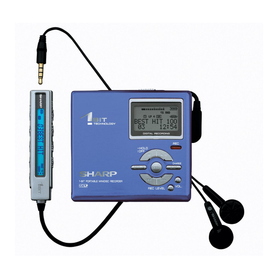
Illustration: MD-DR470H
Illustration: MD-DR480H
SAFETY PRECAUTION FOR SERVICE MANUAL .......................................................................................................... 2
SPECIFICATIONS ............................................................................................................................................................ 3
NAMES OF PARTS .......................................................................................................................................................... 5
DISASSEMBLY ................................................................................................................................................................. 6
REMOVING AND REINSTALLING THE MAIN PARTS .................................................................................................... 7
ADJUSTMENT .................................................................................................................................................................. 8
BLOCK DIAGRAM .......................................................................................................................................................... 25
SCHEMATIC DIAGRAM / WIRING SIDE OF P.W.BOARD ............................................................................................ 26
VOLTAGE ....................................................................................................................................................................... 37
NOTES ON SCHEMATIC DIAGRAM ............................................................................................................................. 38
TYPES OF TRANSISTOR AND DIODE ......................................................................................................................... 38
WAVEFORMS OF MD CIRCUIT .................................................................................................................................... 39
TROUBLESHOOTING .................................................................................................................................................... 41
FUNCTION TABLE OF IC ............................................................................................................................................... 44
PARTS GUIDE/EXPLODED VIEW
SERVICE MANUAL
1-BIT PORTABLE MINIDISC RECORDER
MODEL
CONTENTS
SHARP CORPORATION
MD-DR470H/MD-DR480H
MD-DR470H(S)
MD-DR470H(BL)
MD-DR480H(S)
MD-DR480H(BL)
• In the interests of user-safety the set should be restored to its
original condition and only parts identical to those specified be
used.
This document has been published to be used
for after sales service only.
The contents are subject to change without notice.
No. S1309MDR470HS
Page
Table of Contents

Related Manuals for Sharp MD-DR470HS


Summary of Contents for Sharp MD-DR470HS
-
Page 1: Table Of Contents
TROUBLESHOOTING ..............................41 FUNCTION TABLE OF IC ............................... 44 PARTS GUIDE/EXPLODED VIEW PACKING METHOD (MD-DR470H FOR U.K. ONLY) This document has been published to be used SHARP CORPORATION for after sales service only. The contents are subject to change without notice. -
Page 2: Safety Precaution For Service Manual
MD-DR470H/MD-DR480H SAFETY PRECAUTION FOR SERVICE MANUAL Precaution to be taken when replacing and servicing the Laser Pickup. The AEL (Accessible Emission Level) of Laser Power Output for this model is specified to be lower than Class 1 Requirements. However, the following precautions must be observed during servicing to protect your eyes against exposure to the laser beam. (1) When the cabinet has been removed, the power is turned on without a compact disc, and the Pickup is on a position outer than the lead-in position, the Laser will light for several seconds to detect a disc. -
Page 3: Specifications
MD-DR470H/MD-DR480H FOR A COMPLETE DESCRIPTION OF THE OPERATION OF THIS UNIT, PLEASE REFER TO THE OPERATION MANUAL. SPECIFICATIONS For MD-DR470H Power source: DC 5 V: AC adaptor (AC 230 V, 50/60 Hz) DC 1.5 V: Commercially available, "AA" size (LR6), alkaline battery x 1 DC 1.2 V: Rechargeable Nickel-Metal Hydride battery AD-N55BT x 1 DC 4.5 V:... - Page 4 MD-DR470H/MD-DR480H For MD-DR480H DC 5 V: AC adaptor (AC 110 - 240 V, 50/60 Hz) Power source: DC 1.5 V: Commercially available, "AA" size (LR6), alkaline battery x 1 DC 1.2 V: Rechargeable Nickel-Metal Hydride battery AD-N55BT x 1 DC 4.5 V: Optional car adaptor, AD-CA20X (for cars with a 12 - 24 V DC negative earth electrical system) Power consumption:...
-
Page 5: Names Of Parts
MD-DR470H/MD-DR480H NAMES OF PARTS Main unit 1. Stop/Power Off/Hold Button 2. Group Button 3. Fast Forward/Fast Reverse/Recording Level/ Name Select Buttons 4. Play/Pause Button 5. Record Button 6. Menu Button 7. Display Button 8. Volume Buttons 9. 5 V DC Input Socket 10. -
Page 6: Disassembly
MD-DR470H/MD-DR480H DISASSEMBLY (A1)x2 ø1.4x1.5mm Top Cabinet Cares before disassembling When assembling the machine after disassembling or repair, observe the following requirements so as to ensure (A1)x1 safety and performance. ø1.4x1.5mm 1. Remove the batteries from the machine, and take out the mini-disc. -
Page 7: Removing And Reinstalling The Main Parts
MD-DR470H/MD-DR480H REMOVING AND REINSTALLING THE MAIN PARTS Remove the MD mechanism according to the disassembling (A2)x3 methods 1 to 4. (See Page 6.) ø1.4x1.8mm How to remove the spindle motor (See Fig. 7-1.) Spindle Motor 1. Remove the solder joints (A1) x 4 of flexible PWB. 2. -
Page 8: Adjustment
MD-DR470H/MD-DR480H ADJUSTMENT Test disc MD adjustment needs two types of disc, namely recording disc (low reflection disc) and playback-only disc (high reflection disc). Type Test disc Parts No. High reflection disc MMD-110 (TEAC Test MD) 88GMMD-110 Low reflection disc MMD-213A (TEAC Test MD) 88GMMD-213A Low reflection disc Recording mini disc... - Page 9 MD-DR470H/MD-DR480H Test Mode 1. AUTO 1 Mode • Perform preliminary automatic adjustment. 6. MANU 2 Mode • Temperature is displayed. • If the combination of mechanism and pickup PWB • Seeing the displayed adjustment value, perform has been changed, be sure to start from AUTO1. ATT (attenuator) manual adjustment.
- Page 10 MD-DR470H/MD-DR480H * Pre-mastered disc • When the VOLUME +/– button is pressed in the REC mode or Continuous playback [ S Q continuous record mode, the laser record power changes. (SUBQ address indication) (Servo gain changes also according to record power.) ↓...
- Page 11 MD-DR470H/MD-DR480H Temperature reference setting method. [2] Temperature measurement value correction table. [1] Measurement, calculation and setting procedure. Set the TEST mode. Ambient Temperature Center Activate the “Temp” menu in the “EEPROM” mode. temperature correction temperature • In the test mode stop state, press the MENU button, C ~ +10 - 05 h + 9.2...
- Page 12 MD-DR470H/MD-DR480H Tracking setting Sled setting Item display Item display Set values Set values T G 1 _ S K S _ S K L _ T G 2 _ T F 0 _ S L C _ S T L _ T F 1 _ T F 2 _ S T M _...
- Page 13 MD-DR470H/MD-DR480H Control setting Item display Item display Set values Set values C T 0 _ w E A _ C T 1 _ w E F _ C T 2 _ K 1 0 _ C T 3 _ K 1 1 _ U S A _ ROM Correction setting R C E _...
- Page 14 MD-DR470H/MD-DR480H Do the following when replacing the mechanism, the pickup, the EEPROM (IC402), the LSI (IC201) or the main PWB unit. Enter the test mode, move the pickup to the most internal periphery and execute AUTO1. (Use the disc of MMD-213A.) A U T O 1 PLAY A T 1...
- Page 15 MD-DR470H/MD-DR480H Change of Test Mode Menus MENU T E S T : Test mode stop SKIP UP SKIP DOWN Slide external Slide internal periphery move periphery move SKIP DOWN A U T O 1 : Pre-automatic adjustment menu SKIP UP SKIP DOWN A U T O J SKIP UP...
- Page 16 MD-DR470H/MD-DR480H Servo Pre-automatic Adjustment A U T O 1 : Pre-automatic adjustment menu Adjustment error PLAY A T 1 : During pre-automatic adjustment Adjustment error A D J . N G Normal end : Pre-adjustment error (adjustment value output) A D J . O K : Pre-adjustment normal end (adjustment value output) PLAY A T 2...
- Page 17 MD-DR470H/MD-DR480H Continuous Playback • Continuous playback from current pickup position : Continuous playback menu P L A Y PLAY E r A D J AUTO1 Practice finish ? AUTO2 Practice finish ? AUTO2 Practice No error ? A D J. N G SQ : Continuous playback (pit section) S Q # # # # AP : Continuous playback (groove section)
- Page 18 MD-DR470H/MD-DR480H Continuous Record Enter the EEPROM setting mode, and press the SKIP UP button. Change the MSL setting value from 00 to 08 by using CTRL_ (control setting menu). (If the MSL remains in 00, no signal is recorded.) • Continuous record from the current pickup position : Continuous record menu R E C PLAY...
- Page 19 MD-DR470H/MD-DR480H Servo Pre-Manual Adjustment M A N U 1 : Pre-Manual Adjustment menu PLAY : Temperature code indication T M P : Temperature code SKIP UP SKIP DOWN : A signal offset (AINO) measurement : Measurement value SKIP UP SKIP DOWN : B signal offset (BINO) measurement : Measurement value SKIP UP...
- Page 20 MD-DR470H/MD-DR480H * If the [DISP] button is pressed, the display changes as follows. • ABMAXO measurement value : A-ATT (focus) tentative setting : B-ATT (focus) tentative setting DISP DISP : ABMAXO measurement value indication "1" Mark lighting • LPFABO measurement value : A-ATT (focus) tentative setting : B-ATT (focus) tentative setting DISP...
- Page 21 MD-DR470H/MD-DR480H * If the [PLAY] button is pressed in the B-ATT setting state, the mode is changed to the continuous playback mode. And if the [Remote Controller MODE] button is pressed in the continuous playback state, the mode is changed to the B-ATT setting state of the ATT manual adjustment. : High-reflection pit section B-ATT (focus) setting : Low-reflection pit section B-ATT (focus) setting : Low-reflection groove section B-ATT (focus) setting...
- Page 22 MD-DR470H/MD-DR480H Servo Pre-adjustment Value Check R S L T 1 : Pre-adjustment Value Check menu PLAY : A signal offset measurement value (setting) SKIP UP SKIP DOWN : B signal offset measurement value (setting) SKIP UP SKIP DOWN : E signal offset measurement value (setting) SKIP UP SKIP DOWN : F signal offset measurement value (setting)
- Page 23 MD-DR470H/MD-DR480H ATT Setting Check R S L T 2 : ATT Setting Check menu PLAY : Pit section E-ATT (tracking) setting SKIP UP SKIP DOWN : Pit section F-ATT (tracking) setting SKIP UP SKIP DOWN : Groove section E-ATT (tracking) setting SKIP UP SKIP DOWN : Groove section F-ATT (tracking) setting...
- Page 24 MD-DR470H/MD-DR480H From the front SKIP UP SKIP DOWN : Error history 6 indication E 6 $ $ $ $ : Error code SKIP UP SKIP DOWN : Error history 7 indication E 7 $ $ $ $ : Error code SKIP UP SKIP DOWN : Error history 8 indication...
-
Page 25: Block Diagram
MD-DR470H/MD-DR480H Figure 25 BLOCK DIAGRAM – 25 –... -
Page 26: Schematic Diagram / Wiring Side Of P.w.board
MD-DR470H/MD-DR480H MAIN PWB-A MAIN PWB-A IC243~IC245: MPX. PLAYBACK SIGNAL IC243 RECORD SIGNAL NC7SZ157P6X IC245 NC7SZ157P6X C233 R233 470P IC244 NC7SZ157P6X C109 C111 C112 0.033 C110 C107 C106 0.22 0.033 C108 CK139 1234 C131 CK111 CK112 ADAGI C132 CK113 DIFF ADAGC 0.22 CK114 ADIPNF... - Page 27 MD-DR470H/MD-DR480H MPX. SHIFT RESISTOR C243 C241 IC241 157P6X 7MH165FK S/L- CK INH SZ157P6X D-FLIP FROP IC203 C208 74LVX74T C244 157P6X S/L- CK INH ROUT ROUTX C242 LOUTX LOUT C240 0.015 IC242 Q213 R214 RT1N441 U 7MH165FK 100K SHIFT RESISTOR Q212 3LN01 S +1.0V Q211...
- Page 28 MD-DR470H/MD-DR480H MAIN PWB-A OPIC OPTICAL PICKUP TP352 HEAD DRIVER EFMOX IC351 EFMO 74ACT08T C357 R352 330K R351 VCC_HEAD C353 DSPDAT DSPSTB C602 DSPSCK D351 T– C351 5 4 3 SBE803 33P(CH) RMDAT C601 F– C604 OPICGA C603 1 2 3 SGAIN DISC C652...
- Page 29 MD-DR470H/MD-DR480H 4.00 MHz XL401 IC402 R411 24WC05UI2 100K TP409 TP410 TP408 TP407 TP411A TP411 EEPROM RMTCNT SPIN LDVAR R442 25 24 23 22 21 20 19 18 17 16 15 14 13 12 11 10 9 8 7 6 5 4 3 2 1 LSIVER EEPK EEPD...
- Page 30 MD-DR470H/MD-DR480H MAIN PWB-A C509 C510 IC701 R719 5.6K IR3R61U6 C734 0.47 AUDIO INPUT AMP. MCINL MOUTL C500 BIAS C503 3.3/10 MINL MGND 7 6 5 4 3 2 1 19 20 R703 100K 9 10 11 12 13 14 15 16 +2.5V PCNT1 TP771...
- Page 31 MD-DR470H/MD-DR480H Q711 C717 2SD2351 W R720 R712 5.6K 6.8K IC701 R719 J701 5.6K OPTICAL/ IR3R61U6 C715 R711 C734 LINE IN TP706 6.8K 0.47 AUDIO INPUT TP708 Vout AMP. C713 R713 TP707 MCINL LATCH RCAULT TP701 C712 L702 TP702 MOUTL CLOCK AUSCLK L703 100P(CH)
- Page 32 MD-DR470H/MD-DR480H MAIN PWB-A C768 Q751 Q761 MCH6630 MCH6630 C767 TP743 +2.5V Q843 FDG312 P R870 330K 4.5V REGULATOR R841 100K IC842 +2.3V 6209B45M JACKIN C840 DCEXT RCPCNT TP731 D843 D844 C844 MA793 MA793 D862 L862 10 µH DG1H3 IC813 C843 D841 74LCX244T DG1H3...
- Page 33 MD-DR470H/MD-DR480H 0.47 TP725 R– TP721 R– TP722 L– TP724 C491 L457 L761 TP727 22 µH RDATA L458 TP728 C783 0.47 L751 R773 22 µH L– L– C771 0.47 Q493 FDG312 P C493 0.047 R495 330K Q701 RT1P441 U TP743 Q702 RT1P441 U VCC4_5 +4.5V...
- Page 34 MD-DR470H/MD-DR480H SW901 TP726 TP741 PROTECT TP712 TP701 SW402 OPEN TP711 TP705 TP725 TP723 TP704 TP808 C701 L752 L762 TP724 TP702 TP406 L491 TP742 TP722 TP727 TP801 TP713 TP812 IC771 TP771 TP403 Q801 TP714 C493 C767 TP708 R495 Q493 Q701 L610 TP453 TP813 Q702...
- Page 35 MD-DR470H/MD-DR480H : Through-hole where the top, bottom and +B patterns are connected. : Through-hole where the top, bottom and ground patterns are connected. : Through-hole where the top and bottom patterns are connected. J701 J702 J703 OPTICAL/LINE IN MIC IN REMOTE CONTROL/HEADPHONES SW401 EJECT...
- Page 36 MD-DR470H/MD-DR480H P35 9 - G TO MAIN PWB CN101 M903 LCD UNIT (227) OPTICAL PICKUP(17) LIFT MOTOR M901 REC. SPINDLE MOTOR STOP PLAY/ PAUSE DISP GROUP MECHANISM MENU FLEXBLE PWB (15) VOLUME SKIP SKIP DOWN VOLUME DOWN M902 OPERATION BUTTON SLED MOTOR FLEXBLE PWB ASS'Y (226) CN601...
-
Page 37: Voltage
MD-DR470H/MD-DR480H VOLTAGE (TEST mode: "TEST" on the LCD display) 'P' in the VOLTAGE column indicates pulse signals. IC101 IC201 IC401 IC601 IC701 IC821 Q721 Q809 VOLTAGE PIN VOLTAGE PIN VOLTAGE VOLTAGE VOLTAGE VOLTAGE VOLTAGE VOLTAGE VOLTAGE VOLTAGE 0.7 V 1.2 V 2.5 V 4.5 V 2.5 V... -
Page 38: Notes On Schematic Diagram
MD-DR470H/MD-DR480H NOTES ON SCHEMATIC DIAGRAM • Resistor: To differentiate the units of resistors, such symbol as K and REF. NO DESCRIPTION POSITION M are used: the symbol K means 1000 ohm and the symbol SW401 EJECT OFF—ON M means 1000 kohm and the resistor without any symbol is SW402 OPEN OFF—ON... -
Page 39: Waveforms Of Md Circuit
MD-DR470H/MD-DR480H WAVEFORMS OF MD CIRCUIT Normal playback, focus access Start of normal playback 13-Sep-02 CHANNEL 1 13-Sep-02 CHANNEL 4 14:12:19 14:24:18 Trace Trace 50 ms - 5 s 0.50 V 0.50 V CK208 FEMON Coupling Coupling CK208 50 ms - 5 s 0.50 V ZOOM 1.00 V... - Page 40 MD-DR470H/MD-DR480H 11-Sep-02 Playback Recording CHANNEL 4 15:59:35 11-Sep-02 TRIGGER SETUP Trace 17:49:30 1 ms Edge SMART 2.00 V 5 µs IC201 IC501 2.00 V 26 Pin Coupling 10 Pin SPDRF LRCK 1 ms 5 µs trigger on 2.00 V ZOOM IC201 2 3 4 Ext IC501...
-
Page 41: Troubleshooting
MD-DR470H/MD-DR480H TROUBLESHOOTING Use the test mode which indicates trouble causes before repairing the unit. This mode records maximum 10 past error causes as codes. Refer them for repairing. Preparations If dusts and foreign materials are accumulated on the pickup lens, playback sounds can be skipped or the TOC (Table of Contans) can't be displayed. - Page 42 MD-DR470H/MD-DR480H • Abnormal display Is a waveform found in pins 8 to 10 of CN451 ? Is a waveform found in pins 29 to 31 of IC401 ? Is pin 2 (VCC) and pin 6 (GND) of CN451 normal ? Check around IC401.
- Page 43 MD-DR470H/MD-DR480H • Recording/playback operation Insert a low reflection disc, and ascertain audio output by normal playback, and then set TEST REC mode. Change MSL from 00 to 80 by the control setting of EEPROM. After completing the operation, return in to 00 Check voltage of pins 90 and 91 of IC201, pins 17, 18, 20, and 21 Does the head move down, failing to start record even when of IC601, pins 8 and 9 of CN601.
-
Page 44: Function Table Of Ic
MD-DR470H/MD-DR480H FUNCTION TABLE OF IC IC201 VHiLR37820+-1 : Endec/Servo/Atrac (LR37820) (1/3) Terminal Name Input/Output Function Pin No. EFMMON Analog Output EFM monitor output. AVCC1 Input Analog power supply. (For EFM system) EFMI Analog Input EFM signal input from RF amplifier. AGND1 —... - Page 45 MD-DR470H/MD-DR480H IC201 VHiLR37820+-1 : Endec/Servo/Atrac (LR37820) (2/3) Terminal Name Input/Output Function Pin No. RAA8 Output Address output to external D-RAM. ADR8 RAOEX Output Data output enable signal output to external D-RAM. DGND — Digital GND. RACASX Output Column address strobe signal output to external D-RAM. RAD2 Input/Three-state Output Data input/output with external D-RAM.
- Page 46 MD-DR470H/MD-DR480H IC201 VHiLR37820+-1 : Endec/Servo/Atrac (LR37820) (3/3) Terminal Name Input/Output Function Pin No. DGND — Digital GND. 105* SBCK Schmidt Input/ DIN subcode read clock. Expansion port 3. Three-state Output Output DIN subcode serial data. Expansion port 2. 107* SBSY Output DIN subcode block sync signal.
- Page 47 MD-DR470H/MD-DR480H IC401 RH-iX0588AWZZ : System Microcomputer (IX0588AW) (1/2) Port Name Terminal Name Input/Output Function Pin No. MCMON Output Internal operation status monitor. LDVAR Output P.U. laser power setting output. EPRT Output EEPROM write protect control output. TB1IN SPIN Input Spindle motor FG pulse detection input. TB0IN Input Track cross signal/focus drive detection.
- Page 48 MD-DR470H/MD-DR480H IC401 RH-iX0588AWZZ : System Microcomputer (IX0588AW) (2/2) Port Name Terminal Name Input/Output Function Pin No. DISCPR Input Disc recording inhibition switch input. PBLAT Output Audio IC data latch output. RFPCNT Output RF-LSI power supply ON/OFF control output. RADAT Output Audio IC serial data output.
- Page 49 MD-DR470H/MD-DR480H IC601 VHiLV8221T+-1 : Motor Driver (LV8221T) (1/2) Port Name Function Pin No. SPGND GND of spindle output section. SPVS Power terminal spindle drive. A capacitor is connected to the paired GND. Comparator filter terminal for detecting spindle motor position. A capacitor is connected between this and COMIN terminal (PIN).
- Page 50 MD-DR470H/MD-DR480H IC601 VHiLV8221T+-1 : Motor Driver (LV8221T) (2/2) Port Name Function Pin No. SLGND GND of 3-phase thread output section. SUCO Position detection comparator output terminal of thread driver section. 3-phase thread U-phase output terminal. 3-phase thread V-phase output terminal. SVCO Position detection comparator output terminal of thread driver section.
- Page 51 “HOW TO ORDER REPLACEMENT PARTS” To have your order filled promptly and correctly, please furnish the For U.S.A. only following information. Contact your nearest SHARP Parts Distributor to order. 1. MODEL NUMBER 2. REF. No. 3. PART NO. 4. DESCRIPTION For location of SHARP Parts Distributor, Please call Toll-Free;...
- Page 52 MD-DR470H/MD-DR480H PRICE PRICE PART CODE DESCRIPTION PARTS CODE DESCRIPTION RANK RANK L103 RCILZ0060AWZZ AB 100 MHz,Tip Impeder INTEGRATED CIRCUITS AC 10 µH L171 RCILC0356AFZZ L204 RCILC0353AFZZ AB 100 MHz,Tip Impeder IC101 VHIIR3R58M/-1 AM RF Signal Processor,IR3R58M AC 47 µH,Choke L210 RCILC0358AFZZ IC201 VHILR37820+-1...
- Page 53 MD-DR470H/MD-DR480H PRICE PRICE DESCRIPTION PART CODE PARTS CODE DESCRIPTION RANK RANK AC 1 µF,6.3V C601~604 VCKYCY0JB105K R254 VRS-CZ1JB562J AB 5.6 kohms,1/16W AC 0.47 µF,10V C608 VCKYCY1AB474K R255 VRS-CZ1JB273D AA 27 kohms,1/16W AB 0.1 µF,10V C652 VCKYCZ1AB104K R257 VRS-CZ1JB103J AA 10 kohm,1/16W AD 10 µF,6.3V,Electrolytic,Tantalum C701,702 VCSATA0JJ106M...
- Page 54 MD-DR470H/MD-DR480H PRICE PRICE DESCRIPTION PARTS CODE DESCRIPTION PART CODE RANK RANK R852 VRS-CZ1JB103J AA 10 kohm,1/16W GCABB3025AWSA J AT Bottom Cabinet R853 VRS-CZ1JB102J AB 1 kohm,1/16W [For MD-DR470H (S)] R855,856 VRS-CZ1JB224D AA 220 kohms,1/16W GCABB3025AWSB J AT Bottom Cabinet R862 VRS-CZ1JB474D AA 470 kohms,1/16W [For MD-DR470H (BL)]...
- Page 55 MD-DR470H/MD-DR480H PRICE DESCRIPTION PART CODE RANK TINSE0513AWZZ Operation Manual [MD-DR470H for U.K.] TINSE0519AWZZ Operation Manual [MD-DR480H for Australia/New Zealand] TINSX0001AWZZ Operation Manual [MD-DR480H Except for Australia/New Zealand/Korea] TINSZ0896AWZZ Operation Manual [MD-DR480H for Korea] TINSZ0901AWZZ AV Operation Manual [MD-DR470H Except for U.K./ Sweden] TINSZ0902AWZZ AV Operation Manual...
- Page 56 MD-DR470H/MD-DR480H 501x3 503x2 506x2 M901 M902 M903 Figure 5 MD MECHANISM EXPLODED VIEW – 5 –...
- Page 57 MD-DR470H/MD-DR480H 601x2 MD MECHANISM 201-1 601x2 201-2 PWB-A 602x2 601x2 603x2 Figure 6 CABINET EXPLODED VIEW – 6 –...
-
Page 58: Packing Method (Md-Dr470H For U.k. Only)
MD-DR470H/MD-DR480H PACKING METHOD (MD-DR470H FOR U.K. ONLY) Setting position of switches and knobs Remote Control HOLD CANCEL 1. Battery Case GCASZ0005AWSA 10. Packing Case [MD-DR470H(BL)] SPAKC1597AWZZ 2. Battery Carrying Case PCoVW1015AWZZ 11. Spacer, Operation Manual SPAKZ0490AWZZ 3. Connecting Cord QCNWG0029AWZZ 12. - Page 59 MD-DR470H/MD-DR480H — M E M O — – 8 –...
- Page 60 MD-DR470H/MD-DR480H © COPYRIGHT 2003 BY SHARP CORPORATION ALL RIGHTS RESERVED. No part of this publication may be reproduced, stored in a retrieval system, or transmitted in any form or by any means, electronic, mechanical, photocopying, recording, or otherwise, without prior written permission of the publisher.