Table of Contents
Quick Links
Table of Contents

Related Manuals for Honeywell AreaRAE Plus


Summary of Contents for Honeywell AreaRAE Plus
- Page 1 AreaRAE WIRELESS MULTI-GAS, MULTI THREAT DETECTOR...
-
Page 3: Table Of Contents
Table of Contents Product Registration Warnings Features Comparison Standard Contents General Information Key Features Connections User Interface Display Overview Keys And Interface Screen Display For Various Numbers Of Active Sensors Glance Mode Menus Wireless Operation Broadcast On Alarm And Remote Unit Sleep/Wakeup Wireless Control And Submenus ISM Settings Wi-Fi Settings... - Page 4 Turning the AreaRAE Plus/Pro On and Off Turning the AreaRAE Plus/Pro On Turning the AreaRAE Plus/Pro Off Testing Alarm Indicators Pump Status Calibration Status Bump Status Programming Enter Programming in Basic Mode Enter Programming in Advanced Mode Menus and Submenus...
- Page 5 Diagnostic Mode Enter Diagnostic Mode Adjusting Alarm LEDs & Buzzer Adjusting LCD Contrast Pump Stall Threshold Adjustment Exit Diagnostic Mode Alarm Signal Summary Troubleshooting Specifications AreaRAE Plus/Pro Wireless Configurations Sensor Specifications Technical Support RAE Systems by Honeywell Contacts AreaRAE User Manual...
-
Page 6: Product Registration
Receive notification of product upgrades or enhancements Be alerted to Training classes in your area Take advantage of RAE Systems by Honeywell special offers and promotions IMPORTANT! BUMP TEST THE MONITOR BEFORE EACH DAY’S USE Prior to each day’s use, every gas detection monitor should be bump tested to confirm the response of all sensors and activation of all alarms by exposing the monitor to a concentration of target gas that exceeds the low alarm set point. -
Page 7: Warnings
Warnings Read Before Operating This manual must be carefully read by all individuals who have or will have the responsibility of using, maintaining, or servicing this product. The product will perform as designed only if it is used, maintained, and serviced in accordance with the manufacturer’s instructions. CAUTION! Never operate the monitor when the cover is removed. - Page 8 The AreaRAE Plus/Pro multi-gas detector must be calibrated if it does not pass a bump test, or at least once every 180 days, depending on use and sensor exposure to poisons and contaminants. CAUTION! TheAreaRAE, PGM-65XXX shall only be charged using a charger specifically supplied for use with the unit with a maximum output voltage of 12V, 7.5A, 60950-certified.
- Page 9 Le présent appareil est conforme aux CNR d'Industrie Canada applicables aux appareils radio exempts de licence. L'exploitation est autorisée aux deux conditions suivantes : (1) l'appareil ne doit pas produire de brouillage, et (2) l'utilisateur de l'appareil doit accepter tout brouillage radioélectrique subi, même si le brouillage est susceptible d'en compromettre le fonctionnement.
- Page 10 Les antennes installées doivent être situées de facon à ce que la population ne puisse y être exposée à une distance de moin de 20 cm. Installer les antennes de facon à ce que le personnel ne puisse approcher à 20 cm ou moins de la position centrale de l’ antenne.
- Page 11 Without proper protection, data can be compromised. Use the security features of all wireless equipment in your network. Each AreaRAE Plus/Pro has a default name and password. You should change these to personalize them upon first installation, which lessens the potential security risk that an unauthorized user can change the configuration.
- Page 12 AVERTISSEMENT: Comme condition de la certification, un connexion filaire ne peut pas être faite via le port de communication lorsque le détecteur de gaz est dans la zone dangereuse à moins que la zone soit connue pour ne pas être dangereuse. WARNING: Li-Ion rechargeable battery: Only use approved battery pack: W01-3007-000 or W01- 3007-100.
- Page 13 For information on sensor specifications, cross-sensitivities, and calibration information, refer to RAE Systems Technical Note TN-114: Sensor Specifications And Cross-Sensitivities (available for free download from www.sps.honeywell.com). All specifications presented in this Technical Note reflect the performance of stand-alone sensors. Actual sensor characteristics may vary when the sensor is installed in different instruments.
-
Page 14: Features Comparison
Features Comparison The AreaRAE Plus and AreaRAE Plus/Pro share many of the same features and the same housing. This user’s guide details all features, including those that are only available on the AreaRAE Plus/Pro (depending your instrument’s configuration it may be configured with a different number of sensors, different primary radio type, etc.). -
Page 15: Standard Contents
Standard Contents The AreaRAE Pro and AreaRAE Plus kit includes: AreaRAE Pro or AreaRAE Plus monitor with sensors, battery, and wireless options as specified and protective rubber boot installed USB communication cable AC/DC power adapter (90-264VAC input) plus power cords... -
Page 16: General Information
— for hours, days or weeks at a time — the AreaRAE Plus/Pro gives you the right hazard intelligence so you can ensure safety for your teams and the general public. The AreaRAE Plus/Pro also facilitates Industrial Fence-line monitoring and has the capability to trigger additional devices via relays. - Page 17 AreaRAE User Manual...
-
Page 18: Connections
Connections The AreaRAE Plus/Pro has six physical ports located on the left, right, and top sides. The rubber boot has integral caps for covering the ports when they are not in use. IMPORTANT! Keep all ports covered when they are not in use. This keeps moisture and debris out of the ports and contributes to the instrument’s intrinsic safety. -
Page 19: User Interface
User Interface The AreaRAE Plus/Pro’s user interface consists of the display, alarm LEDs, an alarm buzzer, and three keys. Display Overview The LCD display provides visual feedback that includes the sensor types, readings, alarm status, battery condition, and other information. - Page 20 Status Indicator Icons Along the top of most screens are status indicators that tell you whether a function is operating and/or its strength or level. Icon Function Wireless status: the ISM or Wi-Fi radio is on (blinks when it cannot find a network) Wireless status: the ISM or Wi-Fi radio is off ISM or Wi-Fi radio signal 0% to 19% ISM or Wi-Fi radio signal 20% to 39%...
- Page 21 Pump operating normally (alternates between these two icons) Pump blocked (blinks once per second) Datalogging status (shown when datalogging is on, blank when off) Battery voltage is ≥80% Battery voltage is ≥50% and <80% Battery voltage is ≥10% and <50% Battery voltage is <10% Battery error Sensor due for calibration...
- Page 22 Temperature Relative humidity AreaRAE User Manual...
- Page 23 Status Indicator Icons For Instruments Equipped with ISM Radio AreaRAE Plus/Pro instruments equipped with optional ISM radio or Wi-Fi use specific icons to indicate functionality. Icon Description ISM or Wi-Fi power is off Cannot find network Received signal strength is <0 and <20% Received signal strength is ≥20% and <40%...
-
Page 24: Keys And Interface
Keys And Interface The AreaRAE Plus/Pro has three keys: In addition to their labeled functions, [Y/+], [MODE], and [N/-] act as “soft keys” that control different parameters and make different selections within the instrument’s menus. From menu to menu, each key controls a different parameter or makes a different selection. - Page 25 Reverse Direction Sometimes you want to go back to a previous screen rather than advance through an entire set of screens before “wrapping around” to that screen again. To reverse direction: Press and hold [N/-] for 3 seconds. When the arrow changes from pointing to the right to pointing to the left, release your finger.
-
Page 26: Screen Display For Various Numbers Of Active Sensors
“Off”). This can be done in Safety Suite Device Configurator (SSDC). With the AreaRAE Plus/Pro turned off, press and hold [Y/+] to enter Glance Mode. The feature is latched, meaning that it runs even after you release the [Y/+] key. If you see the message “GLANCE DISABLED,”... -
Page 27: Menus
Exit Glance Mode The AreaRAE Plus/Pro exits Glance Mode and turns off when you press the [MODE] key. In addition, if you do not press either key in 60 seconds, the AreaRAE Plus/Pro automatically exits Glance Mode. Menus The reading menus are easy to step through by pressing the [N/-] key. -
Page 28: Wireless Operation
Suite Device Configurator (SSDC) to monitor them, as well as the AreaRAE Plus/Pro. Note: If the AreaRAE Pro or AreaRAE Plus is equipped with Wi-Fi, and Wi-Fi is used as the primary radio instead of ISM, then a Wi-Fi access point substitutes for the RAELink3 Host. -
Page 29: Broadcast On Alarm And Remote Unit Sleep/Wakeup
Broadcast On Alarm And Remote Unit Sleep/Wakeup Using Safety Suite Responder, you can control remote functions in the AreaRAE Plus/Pro. Turn on your AreaRAE Plus/Pro. Start Safety Suite Responder for your system. Click “Dashboard” Program the “Broadcast this message” settings. Select “Broadcast this message” to send a message to the entire system (via ISM or Wi-Fi) when an instrument goes into alarm. - Page 30 Any alarms (sound, lights) on the AreaRAE Plus/Pro will be triggered, and the message appears on its screen: After 60 seconds, the message is cleared and the screen reverts to showing monitoring data. Note: You can select multiple units to send to (Shift-Click to select sequential group, Control- Click to select individuals).
- Page 31 Configurator (SSDC). Put Unit To Sleep (From Safety Suite Responder) If the AreaRAE Plus/Pro is on a network with Safety Suite Responder, you can put it to sleep remotely from the same screen where you send messages. Select the instrument you want to put to sleep.
- Page 32 The instrument stops monitoring immediately, the pump shuts down, and the screen goes dark. Wake Unit Up (At Instrument) When the AreaRAE Plus/Pro is in Sleep mode, the display is dark and no information is shown. To wake it: Press any key on the instrument.
- Page 33 If the password is incorrect, the screen goes dark again. This is an anti-tampering feature. Wake Unit Up (From Safety Suite Responder) If the AreaRAE Plus/Pro is on a network with Safety Suite Responder, you can wake it remotely from the same screen where you send messages.
- Page 34 The instrument should wake up and begin monitoring immediately. AreaRAE User Manual...
-
Page 35: Wireless Control And Submenus
Host, Repeater, and Remote wireless modems in the same AreaRAE network need to be configured with the same Network ID. Each device on the network must have a unique Unit ID. Note: ISM Settings can be adjusted in the AreaRAE Plus/Pro’s Wireless menu under “ISM.” AreaRAE... -
Page 36: Wi-Fi Settings
Bluetooth devices. Secure Wireless Access Point Configuration If Wi-Fi is enabled, an AreaRAE Pro or AreaRAE Plus uses a Wi-Fi wireless network to transmit data related to its current and past activity. To protect these data against unauthorized access, Honeywell recommends the following when configuring your wireless network: Set a unique network name (SSID). -
Page 37: Setting Wi-Fi Communication Parameters In Safety Suite Device Configurator
Wi-Fi-equipped instruments’ parameters for communication must be set in Safety Suite Device Configurator (SSDC). Connect Wi-Fi-equipped instrument via USB to a PC running Safety Suite Device Configurator (SSDC). Place the AreaRAE Plus/Pro in Communications Mode. From the main screen, press [N/-] until you see “Enter Communications Mode?” Press [Y/+]. Select PC. - Page 38 Wi-Fi Power Select either “On” or “Off” to set the default power setting for your Wi-Fi-equipped instrument. Note: Wi-Fi Power can also be turned on or off in the AreaRAE Plus/Pro in the Wireless menu’s “Wi-Fi.” Address Select “Use Static IP Address” if you have a static IP or “Use DHCP” if your system allows dynamic hosting configuration.
- Page 39 Then set your Security Key. Warning! Using a network with security disabled is not recommended. AreaRAE User Manual...
- Page 40 Security Key Depending on the type of security you choose, your key will have to be a different number of characters. IMPORTANT! Configure strong authentication and encryption in your network. WPA2 Personal (also known as WPA2-PSK) with AES encryption is highly recommended. Here are characteristics of the different types, their relative security strength, and the number of characters needed in the key: Security Type...
- Page 41 SSID The SSID (Service Set Identifier) is a case-sensitive unique identifier attached to the header of packets sent over a wireless local-area network. Each wireless network in your range will have its own SSID. Consult with your IT department for the SSID. Server IP This is the destination IP address for the instrument to communicate with a computer running Safety Suite Device Configurator (SSDC).
-
Page 42: Relays For Controlling External Equipment
Relays for Controlling External Equipment The AreaRAE Plus/Pro is equipped with three solid-state relays that are switched by gas sensor alarm conditions or by a pump failure. These relays are always active. All of the relays’ contacts are protected against high in-rush current. The external alarms that are to be connected to the instrument must be suitable for the hazardous location where they are mounted, and supplied from a Class 2 power supply or equivalent. - Page 43 Pinout For Relay Port: Pin1: COM (GND) Pin2: Relay1 output Pin3: Relay2 output Pin4: Relay3 output A mating connector for wiring to external devices is available from electronics distributors: Samtec part number ACP-16-03-G-00.30-S-BC-O-1. Test Setup For Relays: AreaRAE User Manual...
- Page 44 Over alarm. Pump Stall alarm. IMPORTANT! The external devices that are to be connected to the AreaRAE Plus/Pro must be suitable for the hazardous location where they are mounted. The wiring method shall be to local electrical code and installations are subject to acceptance by the authority having jurisdiction.
-
Page 45: Battery
Battery Always make sure the battery is fully charged before using the AreaRAE Plus/Pro. Only use this battery pack in the AreaRAE Plus/Pro (PGM-65XXX): Standard-duration rechargeable Li-ion battery (PN: W01-3007-000 or W01-3007-100) WARNING To reduce the risk of ignition of hazardous atmospheres, recharge, remove or replace the battery only in an area known to be non-hazardous! Do not mix old and new batteries or batteries from different manufacturers. -
Page 46: Battery States
The AreaRAE Plus/Pro begins charging automatically. The display shows that the battery is charging. Green LEDs around the top of the AreaRAE Plus/Pro are used in Diagnostic mode. Charging without a VOC sensor installed: After the battery is fully charged, the display shows the charge when any key is pressed. -
Page 47: External Battery Charger
External Battery Charger You can charge a spare Li-Ion battery with the optional External Li-Ion Battery Charger For AreaRAE (P/N: W01-3005-000). Once the Charger is attached to the battery, plug in the AC adapter’s barrel and the plug the power cord into an AC source. WARNING To reduce the risk of ignition of hazardous atmospheres, recharge, remove or replace the battery only in an area known to be non-hazardous! Do not mix old and new batteries or... -
Page 48: Turning The Arearae Plus/Pro On And Off
Note: If the battery is completely empty, then the display briefly shows the message “Battery Low,” and the AreaRAE Plus/Pro shuts off. You should charge the battery or replace it with a fully charged battery before turning it on again. -
Page 49: Turning The Arearae Plus/Pro Off
Note: For all AreaRAE Plus/Pro instruments with a PID, if the pump is in alarm for more than five minutes, the PID lamp automatically turns off. The display shows a “Lamp” alarm. Click [Y/+] to restart the pump. -
Page 50: Calibration Status
Note: When a pump alarm occurs and the AreaRAE Plus/Pro is monitored by Safety Suite Device Configurator (SSDC), the PID’s reading in SSDC shows “- - -”. Calibration Status The instrument displays this icon next to the sensor that requires calibration: Calibration is required (and indicated by this icon) if: The lamp type has been changed. -
Page 51: Programming
Programming The menu in Programming Mode is to adjust settings, and calibrate sensors. It has the following submenus: Measurement Alarms Datalog Wireless Monitor Calibration Enter Programming in Basic Mode Programming in Basic Mode is limited to calibration only. A password is required to access other programming menus. - Page 52 If you make a mistake, you can cycle through the digits by pressing [N/-] and then using [Y/+] to change the number in each position. Note: The default password is 0000. Note: The password screen appears when you enter the Programming Mode the first time after turning the instrument on in Basic Mode, and each time after that.
-
Page 53: Enter Programming In Advanced Mode
Enter Programming in Advanced Mode To enter Programming Mode, press and hold [MODE] and [N/-] until you see the Calibration screen. No password is necessary in Advanced Mode. Press [N/-] to step through the programming screens. Note: Holding down [N/-] advances quickly through the menu options. When a menu item is selected, its name is shown at the top of the screen, and its icon is enlarged. -
Page 54: Menus And Submenus
There are a few basic ways to edit parameters, select sensors, and perform other activities in the AreaRAE Plus/Pro. The actions performed by pressing keys always match 1-to-1 with the boxes along the bottom of the display and the three keys. Some parameters are edited by scrolling and selecting individual items (black bars behind white text act as highlighters). - Page 55 Multi Sensor Span Depending on the configuration of your AreaRAE Plus/Pro and the span gas you have, you can perform a Span calibration simultaneously on multiple sensors. The selected sensors are shown on the screen, along with the concentration settings for their Span gas.
- Page 56 Single Sensor Zero This allows you to perform zero (fresh air) calibration on individual sensors. Even though most toxic gas sensors can be zeroed in fresh air, some sensors such as a parts-per-billion PID sensor for volatile organic compounds (VOCs) should not be zeroed in fresh air. VOCs are normally present in ambient air, so zeroing these sensors in ambient air will not allow for a true zero to be set for such sensors.
- Page 57 6. Press [Y/+] to start calibrating or wait for calibration to start automatically. 7. A countdown screen appears. You can abort the calibration at any time during the countdown by pressing [N/-]. 12.3.2.4. Single Sensor Span Calibration Instead of performing a span calibration on multiple sensors simultaneously, you can select a single sensor and perform a span calibration.
- Page 58 However, you can check it by placing a check-source on the rear of the AreaRAE Plus/Pro equipped with a gamma sensor to check the readings. Place the check- source near the upper middle of the rear of the instrument and hold it until you see the Gamma reading change in the display.
- Page 59 Note: Dotted line indicates automatic progression. Multi Sensor Bump Depending on the configuration of your AreaRAE Plus/Pro and the span gas you have, you can perform a bump test simultaneously on multiple sensors. The selected sensors are shown on the screen. With calibration gas connected to the instrument, start a multiple bump test by applying gas to the instrument and pressing [Y/+].
- Page 60 To perform a bump test on an individual sensor, follow these steps: At the Calibration Menu, select “Single Sensor Bump.” Scroll down the list using [N/-], and then press [Y/+] to select a sensor to bump test. Install the “T” tube and connect it to a source of calibration gas. Verify that the displayed calibration value meets the concentration specified on the gas cylinder.
- Page 61 Change Cal. Gas You can change the calibration gas for the AreaRAE Plus/Pro’s PID and LEL sensors. Select from a custom list that you create (My List), the last ten gases used, the built-in gas library for your PID lamp, and user-defined custom gases.
- Page 62 Once you have made all your selections, press [MODE] for “Done.” Change Span Value You can individually set the span gas concentration for each sensor. This concentration setting will also be used for a bump test. The units of measure (ppm, %LEL, etc.) are shown on the display.
- Page 63 To calibrate the LEL sensor, follow these two procedures: Zero Sensor Calibration For The LEL Sensor Turn on the AreaRAE Plus/Pro and allow it to warm up for 20 minutes in ambient air. In Programming mode, Select “Calibration” and then select “Single Sensor Zero.”...
- Page 64 Attach the other end to the flow regulator of a calibration cylinder with 50% LEL methane (unless otherwise specified). The flow rate should not be less than 750cc/min. Start the flow of calibration gas. Press [Y/+] to start calibration. When calibration is complete, shut off the calibration gas flow and disconnect the calibration tubing.
- Page 65 Sensor On/Off You can turn sensors on or off via this submenu. An “X” in a box to the left of a sensor’s name indicates it is turned on. Scroll down the list of sensors using the [N/-] key. Add or remove that gas from the list by pressing [Y/+]. An “X” in a box to the left of a sensor’s name indicates it is selected.
- Page 66 Change Meas. Gas The AreaRAE Plus/Pro has extensive onboard gas libraries for combustible gases and VOCs that you can use to configure your AreaRAE Plus/Pro to automatically apply the appropriate correction factors and produce readings in the units of the desired combustible gas or VOC.
- Page 67 Measurement Unit In some cases, the measurement unit for displaying data from sensors can be changed. The type of sensor is shown in the display, and if there is more than one sensor type (VOC, EC, Gamma), they are shown in a list. Depending on the installed sensors, standard available measurement units include: Abbreviation Unit...
- Page 68 (for example, STEL for a gamma radiation sensor), then that sensor does not appear in the list. Alarm Mode You can program the AreaRAE Plus/Pro so that there are two ways to shut off an alarm: Auto When the alarm condition is no longer present, the alarm stops automatically.
- Page 69 Comfort Beep A Comfort Beep is a single beep of the audible alarm at 60-second intervals that informs the person using the AreaRAE Plus/Pro that it is functioning. It can be turned on or off. Datalog The instrument displays a floppy disk icon to indicate that a datalog is being recorded. The instrument stores the measured gas concentration for each sensor, date and time for each measurement, Site ID, User ID, and other parameters.
- Page 70 Sensor Selection You can choose which sensors’ data are included in the datalog. The entire list of installed sensors is shown, and you can individually select whether their data is included. Note: Turning a sensor off in the list does not change or erase its settings. Data Selection Data Selection allows you to select which types of data are stored and made available when you download your datalog to a computer via Safety Suite Device Configurator (SSDC) software.
- Page 71 Datalog Type The instrument offers three options for starting the datalogging process: Automatically collects datalog information every time the instrument is sampling until the Auto datalog memory is full. Manual Datalogging occurs only when you manually initiate it (see below for details). Note: You can only choose one datalog type to be active at a time.
- Page 72 [Y/+] from that screen. Memory Full Action When the internal datalog memory is full, the AreaRAE Plus/Pro can either stop collecting data (Stop When Full) or go back to the beginning and overwrite the data from the first entry, second entry, etc.
- Page 73 For a GPS-equipped AreaRAE Plus/Pro to work properly, it must have a direct line of sight to a satellite, meaning it will not work well (if at all) indoors. Although radio signals from navigation satellites can pass through clouds, glass, plastic and other lightweight materials, satellite navigation receivers do not work underground or in other enclosed spaces.
- Page 74 Press [Y/+] to “Save.” You can also press [N/-] to undo. Mesh The AreaRAE Plus/Pro’s secondary Mesh radio is designed to work in a RAE Systems wireless mesh radio network. This type of flexible, robust wireless network provides reliable, low-cost operation and supports point-to-point and point-to-multi-point networking with Safety Suite Device Configurator (SSDC) software.
- Page 75 Channel The AreaRAE Plus/Pro and any other devices that you want to interconnect wirelessly must be operating on the same channel. 1. Press [N/-] to step through the channel numbers from 1 through 10. 2. Once your selection is highlighted: Press [Y/+] to select the channel.
- Page 76 The AreaRAE Plus/Pro and any other devices that you want to interconnect wirelessly through ISM must have the same Network ID (1 to 4095, but do not use 255), as well as a unique Unit ID (1 through 64). You can set the Network ID in the instrument or through Safety Suite Device Configurator (SSDC).
- Page 77 Unit ID Each instrument in an ISM network must be assigned a unique Unit ID (between 00 and 99). Make sure that the unit ID is not duplicated among any of the units within the same network. Press [Y/+] to increase the number and [N/-] to advance to the next digit. After moving to the last digit and making changes, press [MODE].
- Page 78 In order to communicate via Wi-Fi, you must configure Wi-Fi settings for the AreaRAE Plus/Pro to match your router by using Safety Suite Device Configurator (SSDC): Connect a USB cable between the AreaRAE Plus/Pro and a PC running ProRAE Guardian.
- Page 79 When the instrument has received a message from Safety Suite Device Configurator (SSDC) on the network, “Message” is shown in the Wireless menu on the AreaRAE Plus/Pro. If you scroll to “Message” and press [Y/+] to select it, a message screen is shown. If there are no messages, then the word “Message”...
- Page 80 It skips showing you many settings and is best suited to environments where the AreaRAE Plus/Pro is turned on and off very often during a given day. If Fast Startup is not selected, then when the instrument starts, it shows you details of each sensor, including calibration information, high and low alarm settings, etc.
- Page 81 Note: This feature is disabled by default, and is configurable via Safety Suite Device Configurator (SSDC) and via the AreaRAE Plus/Pro’s menu. Screen Lock: AreaRAE Plus/Pro’s Screen Lock mode prevents changing the screen from the main reading display without first entering a password. When Screen Lock is active, only the instantaneous reading screen is displayed.
- Page 82 monitoring. During alarm events, the display reverts to Screen Lock mode. Once the alarm conditions are cleared, Remote Monitoring mode resumes. Note: If enabled, Remote Monitoring mode is active upon entry to Normal mode, immediately after startup, and/or upon exiting Programming mode. To select a Secure In Place feature (or to disable all of them): Press [Y/+] to see the currently selected mode.
- Page 83 Press [Y/+] to enter the “Password” screen: The AreaRAE can communicate with Safety Suite Device Configurator (SSDC). At this point, you can change the password or Secure In Place setting in Safety Suite Device Configurator (SSDC). Start Safety Suite Device Configurator (SSDC). Click on the device's serial number to view the settings.
-
Page 84: User Modes
User Modes The AreaRAE Plus/Pro can be configured for two user modes, Basic and Advanced. The choice is selected and set in Safety Suite Device Configurator (SSDC). Basic User Mode In Basic User Mode, some restrictions are applied, including password protection that guards against entering Programming Mode by unauthorized personnel. -
Page 85: Policy Enforcement
AreaRAE Plus/Pro screen: If Policy Enforcement is enabled, then after startup the AreaRAE Plus/Pro displays a screen that informs the user that the instrument requires either a bump test or a calibration. If both are required, then they are shown in sequence. - Page 86 In this case, the instrument records that the user has bypassed the bump testing requirement in a Policy Violation report. These are the screens that are shown on an AreaRAE Plus/Pro after startup if “Can Bypass” is selected: If “Can’t Bypass”...
- Page 87 Once you have made your selections inSafety Suite Device Configurator (SSDC), you must upload the changes to the instrument. Click "Save". Exit Safety Suite Device Configurator (SSDC). Press [Y/+] on the AreaRAE Plus/Pro to exit Communication Mode. AreaRAE User Manual...
-
Page 88: Deactivating Policy Enforcement
Deactivating Policy Enforcement If the AreaRAE Plus/Pro screen displays the message that it must be bump tested or calibrated, and if the option to bypass bump testing or calibration is not available, you should shut off the instrument and follow the procedure outlined here if you want to change the Policy... -
Page 89: Calibration And Testing
The AreaRAE Plus/Pro multi-gas detector must be calibrated if it does not pass a bump test when a new sensor is installed, after sensor maintenance has been performed, or at least once every 180 days, depending on use and sensor exposure to poisons and contaminants. - Page 90 Enter the Bump Test menu. It is accessible through Programming Menu. Connect the AreaRAE Plus/Pro to the calibration gas. Turn on the gas to initiate flow. Press [Y/+] to start the bump test. While the bump test is being performed, the readings for each sensor are shown.
- Page 91 The gamma radiation sensor does not require user calibration. To check whether the sensor is operational, place a gamma check-source on the upper half of the rear of the AreaRAE Plus/Pro equipped with a gamma sensor. The reading should increase.
-
Page 92: Span Calibration
Three-Point Calibration for Enhanced Linearity with Extended- Range and ppb PID Sensors For better linearity at higher concentrations when an AreaRAE Plus/Pro is equipped with a PID sensor, a 3-point calibration can be performed. IMPORTANT! Three-point calibration is disabled by default, but can be enabled using Safety Suite Device Configurator (SSDC) Data Management software on AreaRAE Plus/Pro instruments with 10.6eV... - Page 93 Connect the VOC Zero Tube Adapter to the external filter on AreaRAE Plus/Pro, and then insert one end of the VOC Zeroing Tube into the adapter. The arrow on the tube indicates the correct direction.
- Page 94 Enabling 3-Point Calibration for the VOC Sensor Via Safety Suite Device Configurator (SSDC) The AreaRAE Plus/Pro must be connected to a PC through the supplied USB cable and must be in the PC Communications mode. Start up the Safety Suite Device Configurator (SSDC) software, enter a password, and detect the instrument following the directions provided in the Safety Suite Device Configurator (SSDC) User’s Manual.
- Page 95 Best Demand Flow Using a T-Tube Using Teflon tubing, attach one end of a “T” to the external filter on the AreaRAE Plus/Pro inlet. (You can use RAE Systems by Honeywell P/N: W01-3003-000). Calibrating Without a T-Tube Use Teflon tubing to connect the calibration gas cylinder’s regulator to the external filter on the AreaRAE Plus/Pro inlet.
- Page 96 Teflon tubing must be used to test or calibrate the PID sensor. Follow the steps described here to perform a multi-sensor span calibration: Attach the “T” tube and connect gas to the AreaRAE Plus/Pro. Start the flow of gas and then either press [Y/+] to begin calibration or wait for calibration to start automatically once the sensor “senses”...
- Page 97 Press [Y/+] to start calibrating. You can abort the calibration at any time during the countdown by pressing [N/-]. After a timer countdown, the span calibration is done. The LCD will display whether the calibration was successful and the reading for that calibration gas. Note: If the sensor calibration fails, try again.
-
Page 98: Datalog Transfer, Monitor Configuration, And Firmware Upgrades Via Computer
Datalogs can be downloaded from the AreaRAE Plus/Pro to a computer, and firmware updates can be uploaded to the AreaRAE Plus/Pro via the USB port on the side. Use the included USB cable to connect the AreaRAE Plus/Pro to a computer running Safety Suite Device Configurator (SSDC). -
Page 99: Downloading Datalogs And Performing Pc-Based Instrument Configuration And Firmware Upgrades
. Use the supplied PC Communications Cable to connect the AreaRAE Plus/Pro to a PC. Turn on the AreaRAE Plus/Pro. Make sure it is running in Normal mode (with the main measurement screen showing). Activate the PC communications mode on the AreaRAE Plus/Pro by pressing [N/-] repeatedly, starting from the main measurement screen until you reach the “Enter... -
Page 100: Maintenance
Removing/Installing the Rubber Boot In order to open the AreaRAE Plus/Pro, it is necessary to remove the belt clip and the rubber boot. Note that there are two hex screws on the bottom rear side that secure the boot. -
Page 101: Replacing The External Filter
IMPORTANT! An AreaRAE Plus/Pro must not be calibrated or operated without a filter. Operation without a filter may damage the instrument. AreaRAE... -
Page 102: Removing/Cleaning/Replacing Sensor Modules
Install the replacement sensor. It can only go into its slot one way. The connector inside the AreaRAE Plus/Pro and the indexing guides are good visual indicators of how to set the sensor into position. Make sure the indexing keys are aligned and press the sensor into place to ensure it is seated firmly. - Page 103 It is important to understand and acknowledge that HF and HCl sensors are not as easy to use and calibrate as any other EC (electrochemical) sensors, so we recommend strictly following the process described in RAE Systems by Honeywell Technical Note TN-201. In addition, be aware that environmental conditions in end-users' applications, legal requirements, and the level of requested accuracy of the gas detection device towards the target gas determine the frequency of recalibration of the sensors.
- Page 104 7R+ sensors 7R+ sensors Note: The AreaRAE Plus/Pro does not allow duplicate sensors (that is, two or more of the same kind, including, for example, a 4R+ PID and a 7R+ PID) to operate simultaneously. Therefore, if duplicate sensors are inserted in the slots, when the instrument is turned on, it automatically senses the redundancy and only allows operation of one of the sensors, selecting the sensor in the location with the lowest number.
-
Page 105: Cleaning Or Replacing The Pid
Cleaning or Replacing the PID Note: The cleaning procedure is not normally needed. Clean the PID sensor module, the lamp and the lamp housing only when one of the following has happened: The reading is inaccurate even after calibration. The reading is very sensitive to air moisture. A chemical liquid has been sucked into the unit and damaged the unit. - Page 106 Once the cap is removed, set it aside. Now lift the sensor electrode panel from the module: AreaRAE User Manual...
- Page 107 Clean the sensor electrode panel in a solution of isopropanol lamp cleaner (included, along with cleaning swabs, in a PID Lamp Cleaning Kit, part number 500-0014-010, package of 10), and allow it to dry. Clean the lamp’s window with a cleaning swab dipped in isopropanol lamp cleaner, and allow it to dry.
- Page 108 Reassemble the sensor module by placing the sensor electrode panel back in place and firmly pressing the cap back onto the top. Place the sensor module back into the AreaRAE Plus/Pro. Make sure the index points are aligned (it can only go in one way).
- Page 109 Cleaning or Replacing the 7R+ PID Note: Always calibrate the AreaRAE Plus/Pro after replacing the sensor module. Gently lift out the PID module from the instrument with your fingers. If the module requires replacement (because the lamp does not illuminate, or the module has been used past its expiration date), place a new module into the slot, being careful to match the indexing keys.
- Page 110 Place the tip of a flat-blade screwdriver in the slot and gently pry up on the cover, using the tool for leverage. Once the cover is loose, remove the screwdriver. Lift the lid off, exposing the sensor electrode panel. AreaRAE User Manual...
- Page 111 Lift out the sensor electrode panel. The PID lamp’s window is now visible. Use the 7R+ PID Lamp Removal Tool (P/N: C04-2026-000) to remove the lamp. With the tool’s collar retracted (a), press down around the top of the lamp (b). Then press down the collar so that the tool grips the lamp (c).
- Page 112 Cleaning the PID Electrode Panel Place the PID electrode panel into isopropanol. It is highly recommended that an ultrasound bath to be used to clean it for at least 15 minutes. Then dry the electrode panel thoroughly. Never touch the electrodes with your hand. Also use an isopropanol-soaked cotton swab to wipe off the lamp housing where it contacts the sensor when the sensor is installed.
-
Page 113: Replacing The Sensor Compartment Cover
Replace the Lamp Housing Cap. Note: Always fully calibrate the AreaRAE Plus/Pro after replacing the sensor module and/or lamp. Replacing the Sensor Compartment Cover Before replacing the sensor compartment cover, inspect the large O-ring gasket for damage. If it is damaged, discard it and use a new one. -
Page 114: Battery Removal/Replacement
Battery Removal/Replacement The battery is located in a bay in the lower half of the AreaRAE Plus/Pro’s back. Changing the AreaRAE Plus/Pro battery pack requires a Philips screwdriver. To replace the AreaRAE Plus/Pro battery: Turn the instrument off. Remove the filter from the front of the instrument. - Page 115 Slide a new battery into place. Tighten the four screws. WARNING To reduce the risk of ignition of hazardous atmospheres, recharge, remove or replace the battery only in an area known to be non-hazardous! AreaRAE User Manual...
-
Page 116: Raemet Meteorological Sensor (Optional)
If your AreaRAE Plus/Pro is equipped with a RAEMet meteorological sensor (P/N: C04-0970- 000), it is typically removed for storage and must be attached before using it. If the AreaRAE Plus/Pro is on, turn it off. (Never attach or remove the RAEMet sensor without first turning off the instrument’s power.) Lift up the weather-tight rubber cover, located at the end of the handle, to expose the RAEMet receptacle. - Page 117 Note: Do not remove the RAEMet sensor from the instrument while it is in operation. If it is removed from the AreaRAE Plus/Pro during operation, the display shows a “Fail” message to alert you. Note: Keep strong magnets away from the RAEMet sensor. It contains a compass, and strong magnetism can affect its accuracy.
-
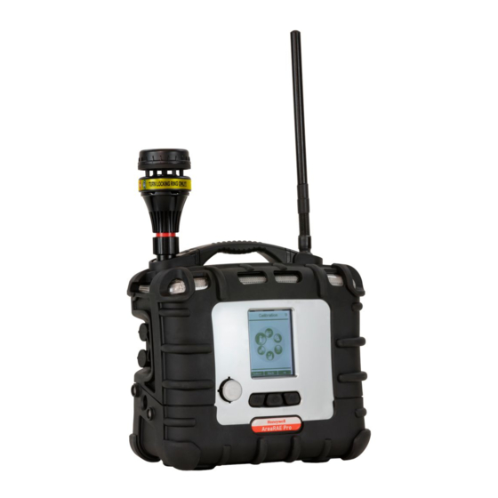
Page 118: Antenna Installation
Antenna Installation Attach the antenna by opening the compartment, aligning the antenna, and turning the base of the antenna until it is snug. IMPORTANT! When the antenna is not attached to the instrument, make sure the cover is securely closed to keep moisture and debris from entering the base. -
Page 119: Voc Carbon Filter For Co Sensor
Replace the gas plate. (Refer to See "Battery Removal/Replacement" on page 113 for more information. for details.) Tighten the four screws. Start the AreaRAE Plus/Pro. Recalibrate the CO sensor. For further information on using a carbon filter to reduce cross-sensitivity to VOCs on a CO sensor, refer to RAE Systems Technical Note TN-121, available at https://sps.honeywell.com/us/en/products/safety/gas-and-flame-detection... -
Page 120: Exhaust Gas Collector For Diverting Output Or Collecting Gas Samples
Exhaust Gas Collector for Diverting Output or Collecting Gas Samples Diverting output gas or collecting samples requires an Exhaust Gas Collector assembly (P/N: W01-3020-000), which includes the Gas Collector Plate and these parts: a male luer connector (P/N: 400-0073-000) and Tygon tubing (P/N: 411-0018-037). Capturing samples requires a Tedlar sample collection bag (3 liters, P/N: 500-0003-000). -
Page 121: Base Plate For Tripod Mounting (Optional)
Once the base plate is firmly attached to the AreaRAE Plus/Pro, stand the instrument up and set it on the tripod. Press up on the tensioning knob until it meets the threads in the middle of the base plate, and then turn until the assembly is tight. -
Page 122: Replacing The Pump
Replacing the Pump If your AreaRAE Plus/Pro’s pump requires replacement, follow these steps. IMPORTANT! Turn off the instrument and remove the battery before proceeding. IMPORTANT! Remove the external filter before proceeding. Remove the sensor compartment cover. Turn it upside down and set it on a soft flat surface. - Page 123 Install two new O-ring gaskets (P/N: 430-B081-0H0) in the compartment’s inlet and outlet. Press a new pump assembly (P/N: W01-3002-000) into place, making sure that both the inlet and outlet from the pump go through the O-rings into the two holes. Insert and tighten the two screws that attach the bracket to the housing.
-
Page 124: Alarms Overview
AreaRAE Plus/Pro user and a remote safety officer (if wireless is enabled) of the alarm condition. In addition to gas and radiation alarms, other alarms are available. -
Page 125: Diagnostic Mode
Diagnostic Mode In Diagnostic Mode, the AreaRAE Plus/Pro provides raw counts for sensor, battery, and other readings, as well as a list of installed sensors and information about them (expiration date, serial number, etc.). Most of these screens are useful only to service technicians. Many allow access for changing settings. -
Page 126: Pump Stall Threshold Adjustment
This prevents unwanted debris or liquid from entering the pump and causing disruption or damage. The AreaRAE Plus/Pro provides two methods to set the pump stall threshold: Static and Dynamic. - Page 127 To change the pump Speed or Stall Algorithm setting: Press [MODE]. Either the pump Speed or the Stall Algorithm is highlighted. To change from “High” to “Low” or “Dynamic” to “Static,” press [Y/+]. Important! The pump Speed must be set to “High” in order to access Dynamic pump stall settings.
- Page 128 Press [MODE] to begin calibration. There is a countdown shown in the box. Press [N/-] anytime to abort the calibration and go back. Once the countdown is finished, this message is displayed: AreaRAE User Manual...
- Page 129 Hold your finger over the inlet, and allow the countdown to proceed. Press [Y/+] anytime to abort and return to the previous screen. When the countdown is finished, the main Dynamic pump stall screen is shown. AreaRAE User Manual...
- Page 130 Dynamic pump stall calibration is complete. You can now exit Diagnostic Mode. Important! When you are done setting thresholds, exit Diagnostic Mode and test the instrument before actual use. AreaRAE User Manual...
- Page 131 Setting Pump Stall Threshold Values – Static Method Use the following values for reference when using the Static method to adjust the pump stall threshold values: Low Speed High Speed Vacuum ≤ -2.5in Hg ≤ -9.6 in Hg Flow rate >200 cc/min >400 cc/min Idle (I)
- Page 132 To calculate the best High value, first add the Blocked and Unblocked values and divide by 2: (Blocked value + Unblocked value) / 2 = correct Stall High value. Press [N/-] to advance to the next Pump screen. Use the [Y/+] and [N/-] keys to increase or decrease the high value input the results of your calculation.
-
Page 133: Exit Diagnostic Mode
Important! When you are done setting thresholds, exit Diagnostic Mode and test the instrument before actual use. Exit Diagnostic Mode Hold [MODE] until the AreaRAE Plus/Pro shuts off. When you start it up again, it is in normal operating mode. AreaRAE... -
Page 134: Alarm Signal Summary
Alarm Signal Summary Hygiene Mode Alarm Type Buzzer & LED Display Reading Backlight Priority Fail 3 beeps/sec “Fail” Blinking reading Highest Fail 3 beeps/sec “Over” or “Fail” at LEL sensor location, depending on signal Blinking Reading Fail 3 beeps/sec “Lamp” at PID location Blinking reading Pump 3 beeps/sec... - Page 135 General Alarms Alarm Message Condition Indications HIGH Gas exceeds “High Alarm” limit beeps/flashes per second Gas exceeds sensor’s measurement range beeps/flashes per second Gas exceeds electronic circuit’s maximum range. If alarm persists in beeps/flashes clean air, it indicates a fault sensor. per second Gas exceeds “Low Alarm”...
-
Page 136: Troubleshooting
Remove the blocking objects and then press [Y/+] key to reset the Solutions: pump alarm. Replace contaminated water trap filter. Be careful not to allow water condensation inside the unit. Replace the pump. If you need replacement parts, a list is available online: https://sps.honeywell.com/us/en/products/safety/gas-and-flame-detection AreaRAE User Manual... -
Page 137: Specifications
Specifications Dimensions 12.6″ x 12.4″ x 6.3″ (322 mm x 315 mm x 160 mm) with boot Weight 13.67 lbs (6.3 kg) Gas Sensor 7 total; see Sensor list on this page Slots Additional Gamma, RAEMet (wind speed, wind direction, temperature, humidity) Sensors* Installed at factory Battery... - Page 138 Protection (IP) Languages Chinese, Dutch, English, French, German, Italian, Portuguese, Russian, Spanish Four years for O2 Liquid Oxygen sensors Three years for CO and H2S sensors Two years for non-consumable components and catalytic LEL sensor Warranty Two years for 10.6eV 7R+ PID lamp One year on all other sensors, battery, and other consumable parts Six months for 9.8eV lamp PID sensor * Optional sensors.
-
Page 139: Arearae Plus/Pro Wireless Configurations
AreaRAE Plus/Pro Wireless Configurations Primary Radio Long Secondary Radio Short AreaRAE AreaRAE GPS BLE Distance Distance Plus Wi-Fi Mesh Model Model PGM- PGM- 1 900 MHz 900MHz 6560A 6520A PGM- PGM- 2 N/A 900MHz 6560E 6520E Americas PGM- PGM- 3 900MHz... -
Page 140: Sensor Specifications
Sensor Specifications Radiation Sensor Range Resolution Gamma 0 to 20,000 µRem/h 1 µRem/h PID Sensors for VOC Range Resolution 4R+; 10.6eV* ppb 0 to 2,000 ppm 10 ppb 4R+ 9.8 eV 0 to 2,000 ppm 0.1 ppm 7R+ 10.6 eV* ppb 0 to 2,000 ppm 10 ppb 7R+ 10.6 eV (Extended Range) - Page 141 Hydrogen Isobutene (Isobutylene) Isopropanol Methane Methanol Methyl ethyl ketone Octane, n- Propane Propene Toluene Turpentine Note: Values in bold type are confirmed with RAE Systems by Honeywell instruments. Others, shown in italic, are calculated from diffusion models. AreaRAE User Manual...
- Page 142 Systems Technical Note TN-156 for more details and other compounds. Caution: Refer to RAE Systems by Honeywell Technical Note TN-144 for LEL sensor poisoning. Year Of Manufacture To identify the year and month of manufacture, refer to the two-digit marking placed adjacent to...
-
Page 143: Technical Support
To contact RAE Systems Technical Support Team: Monday through Friday, 7:00AM to 5:00PM Pacific (US) Time Phone (toll-free): +1 888-723-4800 Phone: +1 408-952-8461 E-mail: [email protected] Web Site: www.sps.honeywell.com Outside the Americas: E-Mail: [email protected] Honeywell Analytics Honeywell Analytics Ltd. ZAC Athélia 4 – 375 avenue du Mistral 4 Stinsford Road Bât B, Expace Mistral... -
Page 144: Rae Systems By Honeywell Contacts
RAE Systems by Honeywell Contacts RAE Systems by Honeywell World Headquarters 300 S Tryon St. Suite 500 Charlotte, NC 28202, USA Phone: +1 888 749 8878 Fax: +1 817 274 8321 E-mail (technical support): [email protected] Web Site: www.sps.honeywell.com WORLDWIDE SALES OFFICES USA/Canada: 1.877.723.2878... - Page 145 Rev C September, 2021 User Manual P/N: W01-4001-000...