
Related Manuals for ABB ACS800 Multidrive


Summary of Contents for ABB ACS800 Multidrive
- Page 1 ACS800 Multidrive Hardware Manual ASFC Switch Fuse Controller Unit for Frame R8i Inverter Modules...
- Page 2 ASFC Switch Fuse Controller Unit Hardware Manual 3AFE68441111 Rev A EFFECTIVE: 29.10.2004 2004 ABB Oy. All Rights Reserved.
-
Page 3: Table Of Contents
Table of contents Table of contents ............. . . 3 About this manual . -
Page 4: About This Manual
Inquiries Address any inquiries about the product to the local ABB representative, quoting the type code and the serial number of the unit. If the local ABB representative cannot be contacted, address inquiries to the manufacturing facility. About this manual... -
Page 5: Hardware Description
ASFC unit overview Frame size R8i inverter modules are connected to the drive DC bus through a switch fuse (type OESL by ABB). The installation is equipped with a Switch Fuse Controller Unit (ASFC) which controls the inverter power switch-on and power switch-off. The unit also... -
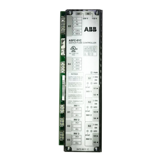
Page 6: Asfc Connectors
ASFC Connectors Connecto Signal Description Charging circuit connection, Inverter 1. Use ABB specified resistors only. IR1+ Inverter 1 (+). Not connected IR1- Inverter 1 (-) Charging circuit connection, Inverter 2. Use ABB specified resistors only. IR2+ Inverter 2 (+). Not connected... -
Page 7: Asfc Settings
ASFC Settings Power supply The jumper settings at connectors X7 and X8 define the voltage level as follows. Voltage 230 VAC 115 VAC Charging circuit monitoring For each inverter module in the system (one to three) there is a charging current monitoring on the ASFC unit. -
Page 8: Asfc Leds
ASFC LEDs Name Colour Indication Illuminates when INV1 STAT Yellow Charging of inverter 1 is Charging monitoring of Inverter 1 is enabled (switch S1 = EN) in progress, or Inverter 1 and charging current is above 0.7 A. is not in use Switch fuse main contacts are open (auxiliary contact connected to connector X4 is open). -
Page 9: Connections Of The Inverter Power Supply
Connections of the inverter power supply Description Drive DC bus Switch fuse 2a: primary contacts - main contacts 1-2 and 3-4 - auxiliary contacts 13-14 to 33-34 2b: secondary contacts - main contacts 1-2 and 3-4 for charging circuit - auxiliary contacts 13-14 to 71-72 for charging circuit 2c: solenoid that operates the locking mechanism of the primary contacts Inverter Charging resistors... -
Page 10: Inverter Power Switch-On Sequence
Inverter power switch-on sequence The terms and designations used in the table below refer to the diagram in section Connections of the inverter power supply. Operation What happens User turns switch fuse Secondary contacts of switch fuse operate. Locking mechanism handle to 1 (On) keeps spring operated primary contacts open. -
Page 11: Miscellaneous
Miscellaneous Details of the locking solenoid control The switch fuse locking is released by the locking solenoid when: • Switch fuse handle in 1 (on) position. (ASFC monitors an auxiliary contact.) • DC voltage of all inverter modules monitored by the ASFC unit exceed 80% of the nominal value. -
Page 12: Installation
Cable selection See ACS800-104 Inverter Module Hardware Manual (3AFE64809032 [English]). Always follow the specification given by ABB. The cables are connected to drive main circuit potential. Protecting against contact Protect the ASFC unit against accidental contact. There are connectors that are connected to drive main circuit potential. -
Page 13: Mounting And Removing The Asfc Unit
ASFC unit [English]). DC fuses for inverter …from ABB or according to the ABB specification. See ACS800-104 Inverter Module Hardware Manual (3AFE64809032 [English]). Charging circuit fuses …from ABB or according to the ABB specification. See ACS800-104 Inverter Module Hardware Manual (3AFE64809032 [English]). -
Page 14: Technical Data
Technical data Power supply input (X5) Operating voltage 230 VAC +10/-15%, 50/60 Hz or 115 VAC +10/-15%, 50/60 Hz Current consumption 40/80 mA typical (230/115 VAC) Protection by Microfuse 2.5 A, slow 6-position detachable screw terminal block, wire size max. 2.5 mm (Wieland 8142) Solenoid control output (X5) Control voltage 115 or 230 VAC, +10/-15%... -
Page 15: Circuit Diagrams Of Inverter Power Supply Equipped With Switch Fuse
Circuit diagrams of inverter power supply equipped with switch fuse What this chapter contains This chapter shows the connections between one switch fuse, one Switch Fuse Control Unit (ASFC) and one, two or three inverters. In each case, the diagrams also show the appropriate ASFC settings (switches S1…S3, jumpers X7 and X8). -
Page 16: One Frame R8I Inverter Module
One frame R8i inverter module Circuit diagrams of inverter power supply equipped with switch fuse... -
Page 17: Two Frame R8I Inverter Modules
Two frame R8i inverter modules Circuit diagrams of inverter power supply equipped with switch fuse... -
Page 18: Three Frame R8I Inverter Modules
Three frame R8i inverter modules Circuit diagrams of inverter power supply equipped with switch fuse... -
Page 19: Dimensions
Dimensions 6 5 . 5 2 3 0 V 1 1 5 V L S O L N S O L A S . C - 0 1 C S W I T C H . U S E C O N T R O L L E R B E U S E D W I T H A B B D R I V E S O N L Y . - Page 20 ABB Oy ABB Inc. AC Drives Automation Technologies P.O. Box 184 Drives & Motors FIN-00381 HELSINKI 16250 West Glendale Drive FINLAND New Berlin, WI 53151 Telephone +358 10 22 11 +358 10 22 22681 Telephone 262 785-3200 Internet http://www.abb.com 800-HELP-365...