Quick Links
SHARP SERVICE MANUAL
PARTS IDENTIFICATIONS AND SPECIFIC INFORMATION ................................................
CAUTIONS FOR USE ............................................................................................................
CLEANING AND MAINTENANCE ..........................................................................................
WIRING DIAGRAM AND CIRCUIT DIAGRAM .......................................................................
COMPONENT REPLACEMENT PROCEDURE .....................................................................
TROUBLESHOOTING ............................................................................................................
SERVICE PARTS LIST ...........................................................................................................
In the interests of user-safety (Required by safety
regulations in some countries) the set should be restore
to its original condition and only parts identical to those
specified should be used.
TABLE OF CONTENTS
SHARP CORPORATION
ELECTRIC FAN
MODEL
PJ-ST161
Page
2
3
3
4
5 - 10
11
12 - 16

Related Manuals for Sharp PJ-ST161


Summary of Contents for Sharp PJ-ST161
-
Page 1: Table Of Contents
SHARP SERVICE MANUAL ELECTRIC FAN MODEL PJ-ST161 In the interests of user-safety (Required by safety regulations in some countries) the set should be restore to its original condition and only parts identical to those specified should be used. TABLE OF CONTENTS Page PARTS IDENTIFICATIONS AND SPECIFIC INFORMATION .......... -
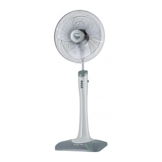
Page 2: Parts Identifications And Specific Information
Adjustable knob Knob switch Grille lock nut Body Blade Spinner fan Front grille Fixing lock Base Wheel SPECIFIC INFORMATION PJ-ST161 Model Rated voltage (V) Rated frequency (Hz) Power consumption (W) Blade (mm) Rated current (A) 0.21 Insulation class Temperature control 0.70... -
Page 3: Cautions For Use
CAUTIONS FOR USE 1. Do not disassemble or repair the electric fan by yourself, it may cause troubles such as a fire of electric shock. Consult your nearest dealer. 2. Incase the power cord is broken, it must be replaced by manufacturer or appointed service providers or equivalent professionals to avoid any damages. -
Page 4: Wiring Diagram And Circuit Diagram
WIRING DIAGRAM MOTOR ASS’Y GEAR BOX CIRCUIT DIAGRAM... -
Page 5: Component Replacement Procedure
COMPONENT REPLACEMENT PROCEDURE REMOVE OF GRILLE ASS’Y 1. Unlock the fixing lock and pull the front grille. 2. Turn the spinner fan clockwise and remove the blade. 3. Turn the grille lock nut counterclockwise and remove the rear grille. Blade Spinner fan Motor ass’y Front grille... - Page 6 REMOVE OF BOTTOM PLATE 1. Remove 2 screws holding base ass’y and detach the unit from the base ass’y. 2. Remove 6 screws holding the bottom plate. 3. Now the bottom plate is free. Unit Base Bottom plate Fig. 3 Screw REMOVE OF POWER CORD 1.
- Page 7 REMOVE OF PIANO SWITCH ASS’Y 1. Remove the power cord in accordance with “REMOVE OF POWER CORD”. 2. Cut 3 lead wires from the piano switch ass’y. 3. Remove 2 screws holding to the piano switch ass’y. 4. Remove the piano switch ass’y from the body, detach the knob switch and remove the insulation sheet from piano switch ass’y.
- Page 8 REMOVE OF LOCK SPRING COVER 1. Remove the base ass’y in accordance with “REMOVE OF BASE ASS’Y”. 2. Remove 2 screws and remove the body cover. 3. Remove 6 screws and separate the front body from back body. (Should be place on jig) 4.
- Page 9 REMOVE OF REEL SPRING 1. Remove the lock spring cover in accordance with “REMOVE OF LOCK SPRING COVER”. 2. Remove the screw holding the reel spring. 3. Now the reel spring is free. Adjustable housing ass’y Screw Screw Reel spring Back body Back body Fig.
- Page 10 REMOVE OF HINGE ASS’Y 1. Remove the motor ass’y in accordance with “REMOVE OF MOTOR ASS’Y”. 2. Remove 2 screws holding the hinge ass’y to the neck. 3. Remove screw holding the link rod to the turning axle. 4. Now the hinge ass’y is free. Screw Link rod Turning axle...
-
Page 11: Troubleshooting
TROUBLESHOOTING Problem Possible Cause Corrective Action 1. Motor does not operate. 1. Connector of power supply cord. Fan does not operate. 2. Repair. 2. Faulty connect the power connector or switch. 3. Coil stator shock or lack of. 3. Replace motor or stator parts 4. -
Page 12: Service Parts List
SERVICE PARTS LIST PARTS CODE REF. NO DESCRIPTION Q’TY PRICE (FEC) PRINTING & PACKAGING MATERIAL 10A102 INSTRUCTION BOOK 10C101 CARTON BOX 10C103 NAME PLATE 10C107F UPPER PAD - F 10C107B UPPER PAD - B 10C108A ST PARTITION - A for BASE 10C108B ST PARTITION - B for BLADE 10A108C... - Page 13 PARTS CODE REF. NO DESCRIPTION Q’TY PRICE (FEC) MECHANICAL PARTS 10A207LBE MOTOR COVER Beige 10A207DDG MOTOR COVER Dark Grey 10A207LLG MOTOR COVER Leaf Green 10A207LRD MOTOR COVER 10A207LTQ MOTOR COVER Turquoise 10A207DWH MOTOR COVER White 10A211LBE CLUTCH KNOB Beige 10A211DDG CLUTCH KNOB Dark Grey 10A211LLG...
- Page 14 PARTS CODE REF. NO DESCRIPTION Q’TY PRICE (FEC) MECHANICAL PARTS 2-17 10C222LBE BACK BODY Beige 10C222DDG BACK BODY Dark Grey 10C222LLG BACK BODY Leaf Green 10C222LRD BACK BODY 10C222LTQ BACK BODY Turquoise 10C222DWH BACK BODY White 2-18 10C208BEASY KNOB SWITCH ASS’Y Beige 10C208DGASY KNOB SWITCH ASS’Y...
- Page 15 PARTS CODE REF. NO DESCRIPTION Q’TY PRICE (FEC) FIXING PARTS 250C0510N SCREW M/C B-PH Ni 3/16”*10 for Motor Cover 124C0410 SCREW TAP P-PH+PT Ni M4*10 for Hinge 130C03510L เกลี ย วซ้ า ย SCREW TAP T-PH+B Ni M3.5*10 ( for Link Rod + Motor 405H0400 WAVE SPRING WASHER for Link Rod...