ABB VM1 Installation And Service Instructions Manual
Hide thumbs
Also See for VM1:
- Installation and service instructions manual (56 pages) ,
- Instruction manual (56 pages) ,
- Manual (52 pages)
Quick Links
—
M E D I U M V O LTA G E P R O D U C T S
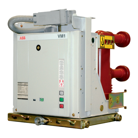
VM1
Installation and service instructions
12 ... 24 kV - 630 ... 2500 A - 16 ... 31.5 kA
Table of Contents
I.
Introduction
II. Programme for environmental protection
1. Packing and transport
2. Checking on receipt
3. Storage
4. Handling
5. Description
6. Structure
7. Operation
8. Circuit breaker characteristics
9. Installation
10. Putting into service
11. Maintenance
12. Application of the standards for X-ray
emission
13. Spare parts and accessories
3
4
5
6
7
8
9
10
14
22
38
52
54
57
58

Related Manuals for ABB VM1


Summary of Contents for ABB VM1
- Page 1 — M E D I U M V O LTA G E P R O D U C T S Installation and service instructions 12 ... 24 kV - 630 ... 2500 A - 16 ... 31.5 kA Table of Contents Introduction II.
- Page 2 • Pay special attention to the notes indicated in the manual by the following symbol: Responsible behaviour safeguards your own and others’ safety! For any requests, please contact the ABB Assistance Service.
- Page 3 M E D I U M V O LTA G E P R O D U C T S — I. Introduction This publication contains the information needed to install medium voltage VM1 circuit breakers and put them into service. For correct use of the product, please read it carefully.
- Page 4 VM1 - USER MANUAL — II. Environmental protection programme The VM1 circuit breakers are manufactured in accordance with the ISO 14000 Standards (Guidelines for environmental management). The production processes are carried out in compliance with the Standards for environmental protection in terms of reduction in energy consumption as well as in raw materials and production of waste materials.
- Page 5 M E D I U M V O LTA G E P R O D U C T S — 1. Packing and transport The circuit breaker is shipped in special packing, in the open position. Each piece of apparatus is protected by a plastic cover to prevent any infiltration of water during the loading and unloading stages and to keep the dust off during storage.
- Page 6 The apparatus is only supplied with the accessories specified at the time of ordering and NR..– V ... validated in the order confirmation sent by ABB. – V ... The accompanying documents inserted in the shipping packing are: • instruction manual (this document)
- Page 7 M E D I U M V O LTA G E P R O D U C T S — 3. Storage When a period of storage is foreseen, our workshops can (on request) provide suitable packing for the specified storage conditions. On receipt the apparatus must be carefully unpacked and checked as described in Checking on receipt (chap.
- Page 8 VM1 - USER MANUAL — 4. Handling Before carrying out any operations, always make During handling, take great care not to stress the sure that the capacitors are discharged. insulating parts and the terminals of the circuit To lift and handle the circuit breaker, proceed as breaker.
- Page 9 5.1. Standards and regulations Altitude 5.1.1. Fabrication < 1000 m above sea level. The VM1 circuit breakers conform to the following Standards: 5.2.2. Special service conditions • VDE 0670, part 1000, and IEC 60694 Installations over 1000 m a.s.l. • DIN VDE 0670, part 104, and IEC 62271-100 Possible within the limits permitted by reduction of the • DIN VDE 0847, part 4, and IEC 61000-4.
- Page 10 VM1 - USER MANUAL — 6. Structure 6.1. Drive structure 6.1.1. Structure of the control module The control module (5) of the circuit breaker The drive is of the magnetic type and basically consists of: consists of the magnetic actuator (6) (fig. 4), the • a microprocessor...
- Page 11 M E D I U M V O LTA G E P R O D U C T S 11 11 6.1.2. Capacitor - The energy available is sufficient for one opening The energy for operating the circuit breaker is operation within 60 s from interruption of the stored in one or two capacitors according to the auxiliary power supply.
- Page 12 VM1 - USER MANUAL — 6. Structure 6.2. Structure of the circuit breaker With the circuit breaker closed, the current flows from the top terminal (1) to the fixed contact (2a) poles in the vacuum interrupter (2), and then through...
- Page 13 M E D I U M V O LTA G E P R O D U C T S 6.3. Basic structure of the with- drawable circuit breaker The withdrawable truck (4) (fig. 8), either manual or motorised, consists of a steel sheet structure with wheels (3), on which the circuit breaker with the relative auxiliary components, the isolating contacts (2) for electrical connection with the...
- Page 14 7.1.1. Magnetic actuator capacitors which allow circuit breaker operation, The magnetic actuator used in the VM1 circuit for a maximum time of two minutes, even in the breakers generates the run required to operate case of a drop in the auxiliary voltage, are the moving contacts of the interrupters and provided in the control circuit.
- Page 15 M E D I U M V O LTA G E P R O D U C T S 7.1.2. Opening and closing operations • The anti-pumping function ensures that only one The opening and closing operations can either be closing-opening cycle is carried out when a closing remotely controlled by means of the special inputs command followed by an opening command is...
- Page 16 VM1 - USER MANUAL — 7. Operation 7.1.5. “READY” signalling 7.1.6. Truck locking magnet (compulsory device) The luminous signal and relative “READY/NOT The locking magnet is inserted in withdrawable READY” contacts signal: circuit breakers with manual movement and • capacitor/s charged prevents traverse of the withdrawable truck when • detection of the correct “CLOSED”...
- Page 17 - opening pushbutton input (the circuit breaker re-opens after the set delay time) - luminous “READY” signal on off Selector not used for the VM1 circuit breaker (the position selected does not matter) Connector for input signal of on off...
- Page 18 Interlocks in the case where ABB withdrawable trucks are used vacuum interrupter 1) The VM1 circuit breaker can only be closed by means of the logical input when a voltage of 24 Given the relatively low static pressure of the...
- Page 19 VM1 circuit-breaker is closed, the two additional auxiliary contacts interlocked with slide locking device is outside the base plate (2) the mechanical interlocks.
- Page 20 VM1 - USER MANUAL — 7. Operation 7.3.4. Characteristics of the control module contacts without potential The contacts without potential are supplied with special relays. For the characteristics of the contacts, please see the table and curves given below. Notes –...
- Page 21 M E D I U M V O LTA G E P R O D U C T S 21 21 I (A) Curve A Maximum power applicable (V d.c. on resistive load). τ = 0 ms Cosϕ = 1 Cosϕ...
- Page 22 VM1 - USER MANUAL — 8. Circuit breaker characteristics 8.1. General characteristics of fixed circuit breakers (12 – 17.5 - 24 kV) Circuit breaker VM1 12 ( IEC 62271-100 • Standards CEI 17-1 (File 1375) • Rated voltage Ur [kV] 12 Rated insulation voltage...
- Page 23 M E D I U M V O LTA G E P R O D U C T S VM1 17 ( VM1 24 • • • • 17.5 17.5 50-60 50-60 1250 1250 1600 1600 2000 2000 2500 1250...
- Page 24 8.1.1. Types of circuit breakers available in the fixed version Complete the circuit breaker selected with the optional accessories indicated on the following pages. VM1 fixed circuit breaker without bottom and top terminals Rated normal current (40 °C) [A] H = 461...
- Page 25 M E D I U M V O LTA G E P R O D U C T S VM1 fixed circuit breaker without bottom and top terminals Rated normal current (40 °C) [A] H = 461 H = 599 H = 616 H = 631 H = 642 H = 661...
- Page 26 VM1 - USER MANUAL — 8. Circuit breaker characteristics 8.2. General characteristics of withdrawable circuit breakers for UniGear ZS1switchgear (12 – 17.5 - 24 kV) Circuit breaker VM1/P 12 ( IEC 62271-100 • Standards CEI 17-1 (File 1375) • Rated voltage Ur [kV] 12...
- Page 27 M E D I U M V O LTA G E P R O D U C T S VM1/P 17 ( VM1/P 24 • • • • 17.5 17.5 50-60 50-60 1250 1600 1600 2000 2000 2500 1250 1250...
- Page 28 8. Circuit breaker characteristics 8.2.1. Types of withdrawable circuit breakers available for UniGear switchgear Complete the circuit breaker selected with the optional accessories indicated on the following pages. VM1/P withdrawable circuit breaker for UniGear switchgear Rated uninterrupted current (40 °C) [A] W = 650...
- Page 29 M E D I U M V O LTA G E P R O D U C T S VM1/P withdrawable circuit breaker for UniGear switchgear Rated uninterrupted current (40°C) [A] W = 650 W = 800 W = 1000 W = 1000 W = 800 W = 1000 W = 1000 P = 150 P = 210...
- Page 30 VM1 - USER MANUAL — 8. Circuit breaker characteristics 8.3. General characteristics of withdrawable circuit breakers for PowerCube modules (12 – 17.5 - 24 kV) Circuit breaker VM1/P 12 VM1/P 17 PowerCube module PB1 IEC 62271-100 • • Standards CEI 17-1 (File 1375) •...
- Page 31 M E D I U M V O LTA G E P R O D U C T S 31 31 VM1/P 24 VM1/W 12 ( VM1/W 17 ( • • • • • • 17.5 17.5 50-60 50-60 50-60...
- Page 32 8. Circuit breaker characteristics 8.3.1. Types of withdrawable circuit breakers available for PowerCube modules Complete the circuit breaker selected with the optional accessories indicated on the following pages. VM1/P withdrawable circuit breaker - VM1/W for PowerCube modules Rated uninterrupted current (40°C) [A] W = 600...
- Page 33 M E D I U M V O LTA G E P R O D U C T S Withdrawable circuit breaker VM1/P - VM1/W for PowerCube modules Rated uninterrupted current (40 °C) [A] L = 600 L = 750 L = 750 L = 1000 L = 750 L = 1000...
- Page 34 (DN). rated current of the panel (only for ABB UniGear 2) binary inputs (logical inputs) for remote type switchgear).
- Page 35 M E D I U M V O LTA G E P R O D U C T S 8.5. Optional accessories • N. 1 transient contact with momentary closing (for 100 ms) during the opening operation The accessories identified by the same number (DOR).
- Page 36 VM1 - USER MANUAL — 8. Circuit breaker characteristics 3) The functions carried out by the control 8.5.2. Circuit breaker auxiliary contacts module are: It is possible to have electrical signalling of circuit • auto-trip following detection of wrong circuit...
- Page 37 M E D I U M V O LTA G E P R O D U C T S 8.5.3. Transmitted contacts in the truck (-BT1; 8.5.5. Motorised truck (-MT) (only for -BT2) withdrawable version circuit breaker for Transmitted contacts of the withdrawable UniGear switchgear) circuit breaker (installed in the circuit breaker This allows the circuit breaker to be racked-in/out...
- Page 38 VM1 - USER MANUAL — 9. Installation 9.1. General Correct installation is of prime importance. The manufacturer’s instructions must be carefully studied and followed. It is good practice to use gloves to handle the pieces during installation. In = 1250 A...
- Page 39 M E D I U M V O LTA G E P R O D U C T S In = 2500 A In = 2000 A In = 1250 A In = 1600 A In = 630 A - 12-17,5 kV , >...
- Page 40 VM1 - USER MANUAL — 9. Installation 9.3. Preliminary operations 9.5.1. Circuit breakers with withdrawable motorized truck • Clean the insulating parts with clean dry cloths. Carry out the racking-in/racking-out test of the • Check that the top and bottom terminals are clean...
- Page 41 M E D I U M V O LTA G E P R O D U C T S Fig. 13a Note By means of the transmission chain, truck handling carried out using the This may damage the permanent magnet of the motor, therefore all manual lever makes the truck motor armature rotate which, behaving the truck racking-in and racking-out operations carried out using the like a generator, can cause inverse voltage at the connection terminals.
- Page 42 VM1 - USER MANUAL — 9. Installation 9.6. Power circuit connections of Assembly procedures • Put the connections in contact with the circuit fixed circuit breakers breaker terminals taking care to avoid mechanical stresses (traction / compression) on, for example, 9.6.1.
- Page 43 M E D I U M V O LTA G E P R O D U C T S 9.7. Earthing 9.8.1. Fixed circuit breaker Connection of the circuit breaker auxiliary circuits For the fixed version circuit breaker, carry out must be made by means of the terminal boxes (1) earthing by means of the special screw marked (fig.
- Page 44 VM1 - USER MANUAL — 9. Installation 9.9. Overall dimensions Fixed circuit breakers Fixed circuit breakers ø 1VCD00001 (E0148) ø 1250 31.5 1VCD00001 (E0148) 17.5 1250 31.5 (*) Fixing interchangeable with the previous series (345 x 400). Fixed circuit breakers ø...
- Page 45 M E D I U M V O LTA G E P R O D U C T S Fixed circuit breakers 1VCD00003 ø (E0148) 1600 2000 31.5 1VCD00003 (E0148) 17.5 1600 2000 31.5 (*) Fixing interchangeable with the previous series (345 x 520).
- Page 46 VM1 - USER MANUAL — 9. Installation Fixed circuit breakers 1VCD00005 (E0148) 1250 (*) Fixing interchangeable with the previous series (345 x 520). Fixed circuit breakers 1VCD00006 (E0148) ø ø 1250 31.5 (*) Fixing interchangeable with the previous series (345 x 650).
- Page 47 M E D I U M V O LTA G E P R O D U C T S Fixed circuit breakers 1VCD00007 (E0148) ø 1600 2000 2500 (*) Fixing interchangeable with the previous series (345 x 650).
- Page 48 VM1 - USER MANUAL — 9. Installation Withdrawable circuit breakers for UniGear switchgear and PowerCube modules VM1/P 1VCD00008 (E0148) 1250 31.5 VM1/P 1VCD00008 (E0148) 17.5 1250 31.5 Withdrawable circuit breakers for UniGear switchgear and PowerCube modules VM1/W ( 1VCD00074 (E0148) 1250 31.5...
- Page 49 M E D I U M V O LTA G E P R O D U C T S Withdrawable circuit breakers for UniGear switchgear and PowerCube modules VM1/P 1VCD00009 (E0148) 1600 2000 31.5 VM1/P 1VCD00009 (E0148) 17.5 1600 2000 31.5...
- Page 50 VM1 - USER MANUAL — 9. Installation Withdrawable circuit breakers for UniGear switchgear and PowerCube modules VM1/P 1VCD00011 (E0148) 2500 31.5 VM1/P 1VCD00011 (E0148) 17.5 2000 31.5 Withdrawable circuit breakers for UniGear switchgear and PowerCube modules VM1/P 1VCD00012 (E0148) 1250...
- Page 51 M E D I U M V O LTA G E P R O D U C T S Withdrawable circuit breakers for UniGear switchgear and PowerCube modules VM1/P 1VCD00013 (E0148) 1250 Withdrawable circuit breakers for UniGear switchgear and PowerCube modules...
- Page 52 10.1. General procedures 10.2. Operation of the circuit breaker All the operations regarding putting into service must be carried out by ABB Closing personnel or by suitably qualified customer This can be carried out remotely by applying personnel with in-depth knowledge of the voltage at the -SC2 input, or locally by pressing apparatus and of the installation.
- Page 53 M E D I U M V O LTA G E P R O D U C T S 10.3. Operations before putting • remount the covers which may have been removed during the testing operations; into service • check that there is a sufficient exchange of air in the installation place to avoid overtemperatures;...
- Page 54 VM1 - USER MANUAL — 11. Maintenance Maintenance operations are aimed at ensuring Typical useful life expectancy of a VM1 vacuum trouble-free operation of the apparatus for the circuit breaker is determined by the following longest possible time. factors: In accordance with what is specified in the IEC • embedded vacuum interrupter, maintenance-free up...
- Page 55 • The LEDs on the inductive sensors are activated as soon as the circuit breaker has reached the closing and opening limit positions Note These operations can only be carried out by ABB personnel or suitably qualified and specially trained personnel.
- Page 56 Should maintenance be carried out by the Note Dismantling and replacement of the pole can only be carried out by ABB customer’s personnel, responsibility for personnel or suitably qualified and specially trained personnel, especially the interventions remains with the for the necessary adjustments.
- Page 57 M E D I U M V O LTA G E P R O D U C T S — 12. Application of the X-ray emission Standards One of the physical properties of vacuum It follows that: insulation is the possibility of X-ray emission when • at the rated service voltage the use of vacuum the interrupter contacts are open.
- Page 58 • Circuit breaker auxiliary contacts parts, by ABB personnel or by suitably • Position contact of the withdrawable truck qualified customer personnel with in-depth • Contacts signalling racked-in/isolated knowledge of the apparatus (IEC 60694) • Isolation interlock with the door...
- Page 59 M E D I U M V O LTA G E P R O D U C T S...
- Page 60 More product information: abb.com/mediumvoltage Your contact center: abb.com/contactcenters More service information: abb.com/service The data and illustrations are not binding. We reserve the right to modify the contents of this document following technical developments. © Copyright 2022 ABB. All rights reserved.