Mitsubishi Electric Lossnay LGH-50RVS-E Handbook
Hide thumbs
Also See for Lossnay LGH-50RVS-E:
- Installation instructions manual (31 pages) ,
- Operating instructions manual (7 pages)
Table of Contents
LOSSNAY
HANDBOOK
MODELS
LGH-50RVS-E
LGH-80RVS-E
LGH-100RVS-E
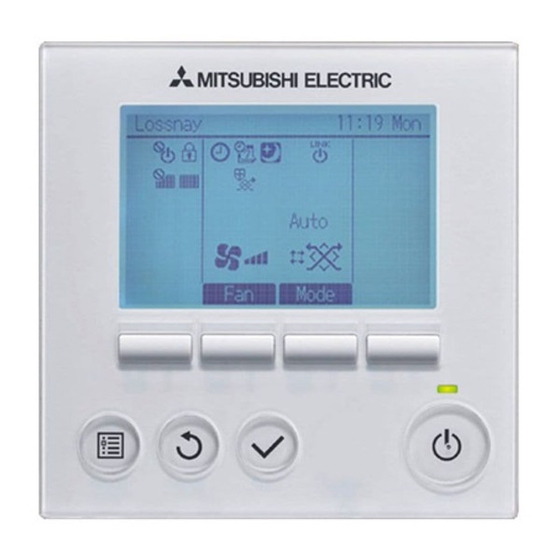
Remote controller
PZ-62DR-E
PZ-43SMF-E
Filter
(Optional)
PZ-S50RFM-E
PZ-S50RFH-E
Warning:
Repair work must be performed by the manufacturer, its service
agent or a similarly qualified person in order to avoid hazards.
(Optional)
PZ-S80RFM-E
PZ-S80RFH-E
September 2021
Nameplate
PZ-S100RFM-E
PZ-S100RFH-E
No. U302-A
Table of Contents

Related Manuals for Mitsubishi Electric Lossnay LGH-50RVS-E


Summary of Contents for Mitsubishi Electric Lossnay LGH-50RVS-E
- Page 1 September 2021 No. U302-A LOSSNAY HANDBOOK MODELS LGH-50RVS-E Nameplate LGH-80RVS-E LGH-100RVS-E Remote controller (Optional) PZ-62DR-E PZ-43SMF-E Filter (Optional) PZ-S50RFM-E PZ-S80RFM-E PZ-S100RFM-E PZ-S50RFH-E PZ-S80RFH-E PZ-S100RFH-E Warning: Repair work must be performed by the manufacturer, its service agent or a similarly qualified person in order to avoid hazards.
-
Page 2: Table Of Contents
Contents Contents 1. Safety precautions ................3 2. Specifications .................. 4 3. Outside dimensions ................ 5 4. Electrical wiring diagrams ............... 7 5. Circuit board diagrams ..............8 6. Troubleshooting ................10 10-34 6-1 Service flowchart ..................10 10-11 6-2 Check Details ..................11 11-34 7. -
Page 3: Safety Precautions
1. Safety precautions Read the following precautions thoroughly before the maintenance, and then inspect and repair the product in a safe manner. The types and levels of danger that may arise if the product is handled improperly are described with the warning symbols shown below. -
Page 4: Specifications
*Temperature Exchange efficiency (%) are based on winter condition. * Mitsubishi Electric measures products according to ISO 16494:2014, therefore P-Q curves are measured by chamber method. * On-site commissioning measurements by pitot tube method could be as much 20% different from ISO test room con- ditions. -
Page 5: Outside Dimensions
Model name PZ-62DR-E PZ-43SMF-E Power supply requirement 12 V DC (Supplied from Lossnay unit) Power consumption 0.3 W Transmission cable Non polarized 2-core cable (0.3 mm (AWG22) sheathed cable) Total wiring length 200 m maximum The number of controllable 15 Lossnay units maximum (Max. 2 remote controllers installable) Lossnay units Environmental condition Temperature: 0°C to 40°C, Humidity: 30% to 90% relative humidity (no condensation) - Page 6 PZ-62DR-E PZ-43SMF-E Unit (mm) Unit (mm) PZ-S50RFM-E, PZ-S80RFM-E, PZ-S100RFM-E, PZ-S50RFH-E, PZ-S80RFH-E, PZ-S100RFH-E Dimension Applicable Model model PZ-S50RFM-E LGH-50RVS-E PZ-S80RFM-E LGH-80RVS-E PZ-S100RFM-E LGH-100RVS-E PZ-S50RFH-E LGH-50RVS-E PZ-S80RFH-E LGH-80RVS-E PZ-S100RFH-E LGH-100RVS-E Notes: • Two filters make one set. • Insert the filters so that the arrow of the marking “AIR FLOW↓” on the filters faces the Lossnay core side. •...
-
Page 7: Electrical Wiring Diagrams
4. Electrical wiring diagrams LGH-50RVS-E, LGH-80RVS-E, LGH-100RVS-E * Wiring for TM1, TM2, TM3, TM4, and TB5 shown in dotted lines are field work. * Be sure to connect the earth wire. * An all pole electric leakage isolator must be installed. * Always use an isolator for the main power connection. -
Page 8: Circuit Board Diagrams
5. Circuit board diagrams Circuit board diagrams and check points (1) Control circuit board Caution: Before servicing (including replacing the circuit boards), be sure to turn off the power supply isolator and check that all the LEDs on the control circuit board and power circuit board are not lit. A large-capacity electro- lytic capacitor on the circuit board may carry voltage for several minutes after the isolator is turned off. - Page 9 (2) Power circuit board Caution: The power circuit consists of live parts. The power circuit board is not insulated from the power line, except for the connection part with the control circuit board. Before servicing (including replacing the circuit boards), be sure to turn off the power supply isolator and check that all the LEDs on the control circuit board and power circuit board are not lit.
-
Page 10: Troubleshooting
6. Troubleshooting Work precautions • Before starting the service, the power supply isolator must be turned off. Pay sufficient attention to avoid elec- tric shock or injury. • When removing or touching the cables, circuit boards or other parts, be sure to turn off the power supply isolator. •... -
Page 11: Check Details
Lossnay does not start properly. (1) Failure mode 1: Lossnay does not work. Lossnay does not work in trial operation, or Lossnay stops working during use. (2) Failure mode 2: The remote controller does not The remote controller does not work. work. - Page 12 [2] Transmission cables (remote controller transmission cable, M-NET transmission cable, external input/output signal cable, and connection cable for IT communication appliances) Check Item Corrective action 1 Are the designated cables used for the remote control- Use the designated transmission cables. ler transmission cable and M-NET transmission cable? (See Table 2-1 and Table 2-2.) 2 Are the designated cables used for the external input/...
- Page 13 Table 2-3 External input/output specifications Terminal or Signal Total Function Name connector on Materials Used specifications extension the circuit board External control input Level/pulse TM2 [Y] [Z] Twisted lead 0.5 to 1.5 mm 500 m (volt-free contact) (Note 4) (Note 1) External control input Level/pulse TM2 [1] [2]...
- Page 14 [3] Monitor output signal cable Check Item Corrective action 1 Is the signal cable wired by multicore cable? Wire the cable using a 2-core cable. 2 Are the signal cables and transmission cables wired Wire the signal cables away from the transmission in the same piping duct? cables.
- Page 15 [5] LED Indications on the circuit boards Contents Check Item Corrective action LED1 Lossnay unit error Blinking: Starting up, error occurred In the case of an error, see Failure (green) indicator Mode 4. Lit: During delay operation Lossnay operates after the delay time has passed.
- Page 16 Individual function check items [6] If Lossnay does not work in the trial operation, or if Lossnay stops working during use, check the following items. Problem Factor Corrective action 1 The fan does not The connectors between the Check the connector (CN9) for the exhaust fan operate even fan motor and circuit board are motor and the connector (CN10) for the supply fan...
- Page 17 Problem Factor Corrective action 3 [When wall-mounted sensor setting is set Check the setting. type CO sensor incorrectly. • When the function setting (No. 66) of PZ-62DR-E PZ-70CSW-E is is set to “0”, the function selection switches used] (SW5-6 to SW5-8) on the Lossnay circuit board The LED display should be: SW5-6 ON, SW5-7 OFF, SW5-8 OFF lamps of the CO...
- Page 18 Problem Factor Corrective action 6 Even though the The indoor negative pressure Check the function selection switches (SW2-4 and remote controller is setting or the indoor positive SW2-5) on the circuit board or the function settings operated to change pressure setting is set. (No.
- Page 19 Problem Factor Corrective action 10 Even though the The outdoor temperature is When the outdoor temperature is 8°C or lower, the remote controller is 8°C or lower. ventilation mode is fixed to the Heat recovery mode. operated to change The signal is input to the Check the Bypass mode switching input (CN26 the ventilation mode, Bypass mode switching input...
- Page 20 Problem Factor Corrective action 13 Actual fan speed The signal is input to the fan Check the fan speed input (CN17). of the Lossnay unit speed input (CN17). (See the Lossnay Operating/Installation differs from the fan Instructions or PZ-62DR-E Instruction Book.) speed set with the The signal (0 to 10 V DC) is Check the fan speed switching input (CN26 [4] [5]).
- Page 21 Problem Factor Corrective action 18 When the supply The Lossnay unit is operating During the intermittent operation, the exhaust fan fan is stopped, the in the protective mode (inter- operates at fan speed 4. exhaust fan oper- mittent operation). (Outdoor ates at the higher temperature is -5°C or lower.) fan speed than...
-
Page 22
Start There is a problem in communication between the Lossnay and the Wi-Fi interface. Is the UNIT lamp on the Wi-Fi interface blinking? [1] Read the QR code of the Wi-Fi interface, and check that the SERVICE REFERENCE is NOT "MAC-567IF-E". - Page 23 (2) Failure mode 2: The remote controller does not work. If the remote controller does not work, check the following items. [1] PZ-62DR-E Problem Factor Corrective action 1 Nothing is displayed The power of the Lossnay unit is Check the items described in (1) [1]. on the remote not ON.
- Page 24 Problem Factor Corrective action 2 “H0” is displayed on The remote controller is starting up. The remote controller displays “H0” during the remote controller. start-up for a maximum of one minute. 3 It takes time for the The Lossnay unit is starting up. The remote controller is not fed with power remote controller to during start-up of the Lossnay unit for a...
- Page 25 Individual check items If the system cannot be started/stopped using the remote controller, check the following items. [1] PZ-62DR-E Problem Factor Corrective action 1 Some Lossnay units in The power of the Lossnay unit Check the items described in (1) [1]. the group do not operate.
- Page 26 Problem Factor Corrective action 7 CO concentration is not With the function setting No. Set the function setting No. 38 to “1: displayed on PZ-62DR-E. 38, CO concentration indica- Available on the screen of PZ-62DR-E”. tion setting is set to “0: N/A”. (See the PZ-62DR-E Installation manual.) The detected CO concen-...
- Page 27 [3] System controller Problem Factor Corrective action 1 The group of The power of the Lossnay unit is Check the items described in (1) [1]. Lossnay cannot be not ON. set with the system M-NET transmission cable is con- Connect the M-NET transmission cable to the controller.
- Page 28 (4) Failure mode 4: Error code and LED display An error code displayed on the remote controller (PZ-62DR-E, PZ-43SMF-E) or the M-NET controller, and blinking or illumination of LED1 (green) or LED2 (red) on the circuit board show the type of an error. The LED blink interval is 0.25 seconds for both on and off.
- Page 29 Error LED1 LED2 Symptom Cause Corrective action Code (green) (red) 4101 Overcurrent Shorting between the remote control- Check the remote controller wiring. blinks error of the ler terminals remote con- The group contains two or more Loss- Set unique addresses to these troller terminal nay units with the same address.
- Page 30 Error LED1 LED2 Symptom Cause Corrective action Code (green) (red) 4116 Abnormal Faulty connection of the exhaust fan Check the connector (CN9) blinks rotation of the motor connector (CN9) on the power connection. exhaust fan circuit board motor Faulty connection of the connectors Check the connector connections (Centrifugal fan (CN14 - CN114 and CN19 - CN119)
- Page 31 Error LED1 LED2 Symptom Cause Corrective action Code (green) (red) 5501 sensor The connectors for the CO sensor Check the connector connections blinks error (Optional are disconnected. (CN34 (only for PZ-70CSW-E), components: CN23, CN26, and CN35) on the PZ-70CSW-E, control circuit board. PZ-70CSB-E) sensor failure Check the CO...
- Page 32 Error LED1 LED2 Symptom Cause Corrective action Code (green) (red) 6603 Transmission Faulty connection of the M-NET Check the items described in (1) blinks error transmission cable [2]. (transmission Wiring was performed with power Restart the system after complet- • bus busy) still supplied to the M-NET trans- ing wiring.
- Page 33 Error LED1 LED2 Symptom Cause Corrective action Code (green) (red) 6801 PZ-43SMF-E Multiple PZ-43SMF-E transmission Using the applicable cable, wire blinks communica- cables are wired using multicore the transmission cable away from tion error cables. one another. The power supply cable is too close Wire the power supply cable at to the PZ-43SMF-E transmission least 5 cm away from the transmis-...
- Page 34 (5) Temperatures and thermistor resistance table Temperature Resistance Temperature Resistance Temperature Resistance Temperature Resistance Temperature Resistance (°C) value (kΩ) (°C) value (kΩ) (°C) value (kΩ) (°C) value (kΩ) (°C) value (kΩ) 64.2 to ∞ 19.4 18.5 37.2 17.7 35.3 16.9 33.5 16.1 31.8...
-
Page 35: Overhauling Procedures
7. Overhauling procedures Work precautions • When touching the electric components such as circuit boards and fan motors, do not touch the components for more than 5 minutes after power-off, and then start working. If LED4 on the circuit board is lit, do not touch the electric components. - Page 36 ( 1 ) Turning power off [1] Shut down the unit. [2] Turn off the power supply isolator. Precaution When servicing, power supply to M-NET must be turned off. Live-line working may cause a circuit board failure. ( 2 ) Fan parts [1] Remove the black screws (three special screws 4×8, Control box cover indicated by...
- Page 37 [4] Loosen the screws (four PT screws 4×8, indicated by ) on the maintenance cover B, and remove the cover. * Note: Remove the maintenance cover B, in the same way as the step [3]. Maintenance cover B also has two keyholes and two fall protection screws.
- Page 38 [8] Open the two snap-in cable clamps on the backside of Circuit board Cable clamp the circuit boards, and remove the motor cables from them. Motor cable [9] Remove the screw (one PTT screw 4×8, indicated by ), and remove the fix piece and the core guide from the unit.
- Page 39 ( 3 ) GM assembly [1] Remove the control box cover. → See (2) [1]. [2] Check that LED4 on the control circuit board is OFF, and then disconnect the geared motor (GM) connector (CN12) from the power circuit board. CN12 Assembly precaution Push in...
- Page 40 ( 4 ) Backflow stopper and drain catch basin [1] Remove the control box cover. → See (2) [1]. [2] Check that LED4 on the control circuit board is OFF, and then remove the maintenance covers. → See (2) [3] and [4]. [3] Remove the filters and inner cover.
- Page 41 ( 5 ) Terminal block parts [1] Remove the control box cover. → See (2) [1]. [2] Check that LED4 on the control circuit board is OFF, Terminal block and then disconnect the connectors (indicated by from the control circuit board. [3] Remove the screw (one PPT screw 4×25, indicated by CN19 CN14...
- Page 42 (6) Control parts Precaution Before replacing the circuit boards, see (7) Procedures for replacing the circuit boards (page 44). [1] Remove the control box cover. → See (2) [1]. [2] Check that LED4 on the control circuit board is OFF, and then disconnect the connectors (indicated by from the control circuit board.
- Page 43 [5] Remove the screws (two PT screws, indicated by and slide the power circuit board to remove it. Power circuit board [6] Remove the sub control base. → See (5) [4]. [7] Disconnect the connectors (indicated by ) from the reactor.
- Page 44 (7) Procedures for replacing the circuit boards Notes • Before removing the circuit boards for replacement, check the following Steps 1 and 2. • When the Lossnay remote controller PZ-62DR-E is connected, be sure to replace the circuit boards as described in the Steps.
- Page 45 Step Details Check item Removing the circuit boards • For the working precautions, see page 35. • For removing the circuit boards, see (6) Control parts (page 42). Attaching the circuit boards [1] According to the function status record data prepared in Step 3, set the address Address setting switches, function selection switches, and model selection switch of the setting...
- Page 46 Step Details Check item Function setting with PZ-62DR-E When PZ-62DR-E is connected, according to the function status record data pre- Address pared in Step 2, set the function settings with PZ-62DR-E. setting If PZ-62DR-E is not connected, skip this step and proceed to Step 7. Function To perform function settings with PZ-62DR-E, see the Lossnay Operating/Installation setting...
- Page 47 (9) Setting status record [1] Basic information Date: Installation location: Model name: LGH- ( 50 . 80 . 100 ) RVS-E Serial number on the nameplate (eight-digit): Address setting: Lot number marked on the circuit board: Microcomputer software version marked on the circuit board: Lossnay remote controller: ( Used .
- Page 48 [3] Function settings Enter the setting data of the functions set with PZ-62DR-E. Function No. Setting Data Function No. Setting Data Function No. Setting Data Function No. Setting Data (15) (10) (15) (10) ( ) : Factory setting [4] External input/output Enter the usage of the external input/output on the control circuit board.
-
Page 49: Parts Catalog
8. Parts catalog Please note the following when using the parts catalog. 1. When ordering parts, the part number, part name, and the number of parts are required. 2. It may take time for you to receive the parts. Make an inquiry about a rush order. 3. -
Page 50: Lgh-50Rvs-E
LGH-50RVS-E 4 pcs. 4 pcs. 4 pcs. 2 pcs. 4 pcs. 2 pcs. 4 pcs. 4 pcs. 2 pcs. 2 pcs. 2 pcs. Special screw 4x9 2 pcs. 2 pcs. 2 pcs. Special screw 4x9 2 pcs. 16 pcs. 2 pcs. 1 pc. - Page 51 LGH-50RVS-E Critical Q'ty Name of part Parts No. Remarks pcs/unit safety Special screw 4x14 W00 000 198 Special washer (4) W50 021 091 Maintenance cover A W50 021 709 Maintenance cover B W50 021 708 Inner cover W50 021 486 Fix piece W50 021 710 Filter...
-
Page 52
Air supply fan assembly (SA) 4 pcs. 6 pcs. 2 pcs. 6 pcs. 2 pcs.
4 pcs. Symbol Screw name PTT screw 4x8 PTT screw 4x25 Air exhaust fan assembly (EA) Note : When removing the separator to replace the fan parts, you need to replace the packing attached on the separator. - Page 53 LGH-50RVS-E Critical Q'ty Name of part Parts No. Remarks pcs/unit safety Special nut (M12) W00 000 117 Left-handed Tab washer W50 004 730 Centrifugal fan W50 004 482 Dia. 245mm Washer (12) W00 000 123 DC motor (SA) W50 021 453 ...
-
Page 54
3 pcs. 2 pcs.
Symbol Screw name PTT screw 4x8 PT screw 4x8 PPT screw 3x8 PPT screw 4x25 ─ 54 ─ LGH-50RVS-E... - Page 55 LGH-50RVS-E Critical Q'ty Name of part Parts No. Remarks pcs/unit safety Special screw 4x8 W00 000 089 Control box cover W50 019 707 Circuit board W50 021 171 Control PCB fix plate W50 021 706 Terminal block W50 021 213 With the lead wires ...
- Page 56 Lossnay unit Control circuit board Power circuit board CN105 CN32 Exhaust fan motor Monitor output CN50 CN26 CN17 PZ-62DR-E 2nd remote controller LED6 (Max. 2 controllers) Supply fan motor 2nd Lossnay unit LED3 (Max. 15 units) LED4 CN10 M-NET transmission cable Shielded Wire CN114 12 V or 24 V DC...
- Page 57 LGH-50RVS-E Critical Q'ty Name of part Parts No. Remarks pcs/unit safety Thermistor W50 021 167 OA・RA set Lead wire W50 021 214 ─ 57 ─...
-
Page 58: Lgh-80Rvs-E
LGH-80RVS-E 4 pcs. 4 pcs. 4 pcs. 2 pcs. 4 pcs. 2 pcs. 4 pcs. 4 pcs. 2 pcs. 2 pcs. 2 pcs. Special screw 4x9 2 pcs. 2 pcs. Special screw 4x9 2 pcs. 2 pcs. 16 pcs. 2 pcs. 1 pc. - Page 59 LGH-80RVS-E Critical Q'ty Name of part Parts No. Remarks pcs/unit safety Special screw 4x14 W00 000 198 Special washer (4) W50 021 091 Maintenance cover A W50 021 709 Maintenance cover B W50 021 708 Inner cover W50 021 486 Fix piece W50 021 710 Filter...
-
Page 60
Air supply fan assembly (SA) 4 pcs. 6 pcs. 2 pcs. 6 pcs. 2 pcs.
4 pcs. Symbol Screw name PTT screw 4x8 PTT screw 4x25 Air exhaust fan assembly (EA) Note : When removing the separator to replace the fan parts, you need to replace the packing attached on the separator. - Page 61 LGH-80RVS-E Critical Q'ty Name of part Parts No. Remarks pcs/unit safety Special nut (M12) W00 000 117 Left-handed Tab washer W50 004 730 Centrifugal fan W50 004 482 Dia. 245mm Washer (12) W00 000 123 DC motor (SA) W50 021 453 ...
-
Page 62
3 pcs. 2 pcs.
Symbol Screw name PTT screw 4x8 PT screw 4x8 PPT screw 4x25 PPT screw 3x8 ─ 62 ─ LGH-80RVS-E... - Page 63 LGH-80RVS-E Critical Q'ty Name of part Parts No. Remarks pcs/unit safety Special screw 4x8 W00 000 089 Control box cover W50 019 707 Circuit board W50 021 171 Control PCB fix plate W50 021 706 Terminal block W50 021 213 With the lead wires ...
- Page 64 Lossnay unit Control circuit board Power circuit board CN105 CN32 Exhaust fan motor Monitor output CN50 CN26 CN17 PZ-62DR-E 2nd remote controller LED6 (Max. 2 controllers) Supply fan motor 2nd Lossnay unit LED3 (Max. 15 units) LED4 CN10 M-NET transmission cable Shielded Wire CN114 12 V or 24 V DC...
- Page 65 LGH-80RVS-E Critical Q'ty Name of part Parts No. Remarks pcs/unit safety Thermistor W50 021 167 OA・RA set Lead wire W50 021 214 ─ 65 ─...
-
Page 66: Lgh-100Rvs-E
LGH-100RVS-E 4 pcs. 4 pcs. 4 pcs. 2 pcs. 4 pcs. 2 pcs. 4 pcs. 4 pcs. 2 pcs. 2 pcs. 2 pcs. Special screw 4x9 2 pcs. 2 pcs. Special screw 4x9 2 pcs. 2 pcs. 16 pcs. 2 pcs. 1 pc. - Page 67 LGH-100RVS-E Critical Q'ty Name of part Parts No. Remarks pcs/unit safety Special screw 4x14 W00 000 198 Special washer (4) W50 021 091 Maintenance cover A W50 021 709 Maintenance cover B W50 021 708 Inner cover W50 021 486 Fix piece W50 021 710 Filter...
-
Page 68
Air supply fan assembly (SA) 4 pcs. 6 pcs. 2 pcs. 6 pcs. 2 pcs.
4 pcs. Symbol Screw name PTT screw 4x8 PTT screw 4x25 Air exhaust fan assembly (EA) Note : When removing the separator to replace the fan parts, you need to replace the packing attached on the separator. - Page 69 LGH-100RVS-E Critical Q'ty Name of part Parts No. Remarks pcs/unit safety Special nut (M12) W00 000 117 Left-handed Tab washer W50 004 730 Centrifugal fan W50 004 482 Dia. 245mm Washer (12) W00 000 123 DC motor (SA) W50 021 453 ...
-
Page 70
3 pcs. 2 pcs.
Symbol Screw name PTT screw 4x8 PT screw 4x8 PPT screw 4x25 PPT screw 3x8 ─ 70 ─ LGH-100RVS-E... - Page 71 LGH-100RVS-E Critical Q'ty Name of part Parts No. Remarks pcs/unit safety Special screw 4x8 W00 000 089 Control box cover W50 019 707 Circuit board W50 021 171 Control PCB fix plate W50 021 706 Terminal block W50 021 213 With the lead wires ...
- Page 72 Lossnay unit Control circuit board Power circuit board CN105 CN32 Exhaust fan motor Monitor output CN50 CN26 CN17 PZ-62DR-E 2nd remote controller LED6 (Max. 2 controllers) Supply fan motor 2nd Lossnay unit LED3 (Max. 15 units) LED4 CN10 M-NET transmission cable Shielded Wire CN114 12 V or 24 V DC...
- Page 73 LGH-100RVS-E Critical Q'ty Name of part Parts No. Remarks pcs/unit safety Thermistor W50 021 168 OA・RA set Lead wire W50 021 214 ─ 73 ─...