Table of Contents
Available languages
Available languages
Quick Links
INSTALLATION MANUAL
Residential Battery Unit
• Please read this manual carefully before operating and retain it for future
reference.
• For stable operation and periodic system updates, LG Electronics highly
recommend the user to subscribe to EnerVu and maintain connection.
Model
BUEL011HBC1 (Pack*3+BCU+Enclosure)
BUEL015HBC1 (Pack*4+BCU+Enclosure)
*MFL1199-00494-00
R e v . 0 1 2 1 / 0 4 / 2 0 2 2
https://www.lg.com/global/business/ess/business-resources/download
Copyright © 2022 LG Electronics Inc. All Rights Reserved.
Chapters
Table of Contents

Related Manuals for LG BUEL011HBC1


Summary of Contents for LG BUEL011HBC1
- Page 1 • Please read this manual carefully before operating and retain it for future reference. • For stable operation and periodic system updates, LG Electronics highly recommend the user to subscribe to EnerVu and maintain connection. Model BUEL011HBC1 (Pack*3+BCU+Enclosure) BUEL015HBC1 (Pack*4+BCU+Enclosure) *MFL1199-00494-00 R e v . 0 1 2 1 / 0 4 / 2 0 2 2 https://www.lg.com/global/business/ess/business-resources/download Copyright © 2022 LG Electronics Inc. All Rights Reserved.
-
Page 2: Safety Information
Do not place objects of any kind on top of the product during operation. y All work on the ESS must be carried out by LG-certified service providers only. y Electrical installations must be done in accordance with the local and national electrical safety standards. - Page 3 Getting Started CAUTION Indicates a situation where damage or injury may occur. y This product is intended for residential use only and should not be used for industrial. y Serious injury may occur due to the heavy weight of the product. Therefore, special care must be taken in handling. Make sure to have at least two persons deliver and move the package. y Do not use any damaged, cracked, or frayed electrical cables or connectors.
- Page 4 Do not store or place any objects on top of or against the product. It may cause serious malfunction or other problems. y This unit is designed and operational for LG ESS PCS Home 8 (D008E1N211) and Home 10 (D010KE1N211) only. Do not connect this unit to a device which makes AC voltage such as an AC power source or a generator.
-
Page 5: First Aid Measures
First Aid Measures The Product includes internal fault mechanisms designed to prevent failures and subsequent risk hazards. However, LG Electronics cannot the guarantee safety performance of the Product if it is ever exposed to abuse, damage, or negligence. If a person is exposed to the internal materials of the battery cell due to damage on the outer casing, the following actions are recommended. -
Page 6: Product Features
Product Specifications All specifications and descriptions contained in this document are verified to be accurate at the time of printing. However, since continuous improvement is a goal at LG Electronics, we reserve the right to make product modifications at any time. -
Page 7: Table Of Contents
Table of Contents Getting Started safety Information ..............2 First Aid Measures . - Page 8 Getting Started Symbol Used on the Labels symbol description The relevant equipment complies with the requirements in the EC guidelines. UL approval Recognized Risk of Electric shock This product should not be disposed of with other household waste. Disposal regulations of the country should be observed. Refer to the installation manual or operating manual.
- Page 9 Getting Started symbol description Disconnect the machine or equipment before carrying out maintenance or repair Take care to avoid causing a fire by igniting flammable material Ensure adequate ventilation of the charging area and take care to avoid coming in contact with acid. In case of contact with acid material, immediately flush the area with plenty of water.
- Page 10 Getting Started Abbreviations in this Manual Abbreviation designation Explanation Energy Storage System Inverter system that stores energy in a battery and uses it. Power Conditioning A device intended to convert AC/DC electricity to System charge and discharge the battery. Photovoltaic A solar panel system that converts solar energy into direct current electricity State of charge...
-
Page 11: Unpacking
Getting Started Unpacking Unpacking the battery unit Unpack the battery unit from its packaging. Remove the packing tape and open the box. Take out the all the accessories and components. Remove the battery unit from the packaging. WARNING y When working on the battery installation, at least 2 people are needed for safe installation and moving. -
Page 12: Contents Of This Product
Getting Started Contents of this product Battery unit Installation Manual & Quick Wall brackets Installation Guide Battery module Power cable harness Communication cable harness (BUEL011HBC1 : 3EA, BUEL015HBC1 : 4EA) Nuts (17 EA) Cable glands (2 EA) - Page 13 Getting Started Additional Components for Installation Applied to Additional components y Refer to "Floor Standing Wall Mount". Wall mounting y Recommended Screw : stainless steel screws with TX M8 x 50mm y Proper anchor to wall type y Follow the local code. y CAT V (better CAT VI) with 4 x 2 x 0.4 mm²...
- Page 14 Getting Started Required Tools Insulated gloves Safety glasses Protective footwear Drill and drill bit 200 mm magnet bit holder and T-Handle Screw driver Hex wrench torque wrench with Phillips (5 mm) Cutter (6 mm, 8 mm) magnet hex socket Flat head (6, 5, 4, 2 mm) (M5, M6, M8) Inclinometer Tape measure...
-
Page 15: Name Of Each Part
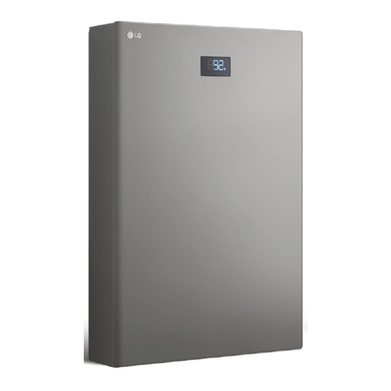
Getting Started Name of each part Front and Rear a LED Indication F Front cover b Cable gland (communication) G Top cover c Cable gland (power) H Wall bracket connected parts D START (5s) button E POWER button... -
Page 16: Connection Parts
Getting Started Connection parts a Circuit breaker of PCS b Power terminals (Positive, GND(Earth), Negative) c Communication terminal D Circuit breaker of battery pack... -
Page 17: Led Indicators
Getting Started LED Indicators status and Indications sOc level + % Error code* Operating Fault charge BAT. Charging Not operating discharge BAT. Discharging Not operating Fault Fault Normal * Refer to "Error Codes and Messages" for more information. -
Page 18: Installation
Installation Installation Location WARNING y Read all of the instructions, cautions, and warnings for the battery unit and documentation on other associated components. y Wear protective gloves when handling equipment. Sharp edges may cause personal injury. y Dispose of the packing materials safely. - Packing materials, such as nails and other metal or wooden parts, may cause puncture wounds or other injuries. - Page 19 Installation y This product is designed to be installed on the floor standing with a wall mounting. Wall mounting is only for supporting purpose. Do not use in case of the wall brackets are used for wall mounting at higher level (without floor standing) as safety concerns may arise.
- Page 20 Installation y Do not install this product in a place with ammonia, corrosive vapours, acids or salts. y Install this product out of reach of children and animals. y Do not install this product in places or environments subject to the heavy build-up of dust.
-
Page 21: Minimum Clearance
Installation Minimum clearance 9 1 5 m m 9 1 5 m m 3 0 0 m m 3 0 0 m m 3 0 0 m m 3 0 0 m m 1 6 0 0 m 3 0 0 m m This product must be installed with clearance at the left, right, top, bottom and front of the product as shown in the figure. -
Page 22: Floor Standing Wall Mount
Installation Floor Standing Wall Mount This product must be installed on the wall considering appropriate environments described in "Installation Location". Be sure to follow this instructions exactly. WARNING y It is important to ensure that the drilling locations are not located on any electrical wiring within the wall. - Page 23 Installation Place the wall bracket on a wall which meets every installation conditions and clearance requirement. And indicate the positions to drill using a pencil or other writing utensil. Drill holes in the indicated positions. (Mount bracket hole guide Template) 406 mm 305 mm Affix the wall bracket to the wall with screws and anchors.
- Page 24 Installation WARNING y The battery unit must be installed on the floor due to its heavy weight. Wall mounting is only for supporting purposes. y Rotate the legs at the bottom of the battery unit to adjust the level. y Install the product on a flat surface. y There should be no foreign object that could damage the bottom of the product.
-
Page 25: Installing Battery Modules
Installation Installing battery modules This product does not have battery modules inside. Before wiring, assemble the battery modules that are separately supplied. WARNING y Wear rubber gloves and protective clothing (protective glasses and boots) when working on high voltage/high current systems such as battery modules. y Before starting electrical connection, make sure that the circuit breaker of PCS and the circuit breaker of battery pack are off securely. - Page 26 Installation Before start the wiring, make sure the circuit breaker of the battery unit is OFF. Place a battery module inside the enclosure and fix the battery module using supplied nuts (2 positions, 25 kgf.cm).
- Page 27 Installation Stacks the remaining battery modules inside the enclosure and fix them with supplied nuts referring to previous step. Nut assembling positions are indicated in the figure. Total number of battery modules may differ depending on your model. Remove protective labels and covers on the power connector of the battery modules. Do not touch the terminals after removing the protective label and cover.
- Page 28 Installation Connect the power cable harness as shown in the figure. Connect the communication cable harness as shown in the figure.
-
Page 29: Wiring Connection Between Battery Unit And Pcs
Installation Wiring connection between battery unit and This product requires an electrical connection to the PCS. Before connecting the battery to the PCS, install the PCS in place where the battery cables can easily access battery unit. Refer to the installation manual of the PCS for more information. Assemble the supplied cable glands to the right side of the battery unit. - Page 30 Installation Remove the connection box cover. When removing the connection box cover, it may be necessary to temporarily remove cables passing through the connection box cover. After completing all connections, temporarily removed cables must be restored to their original state. Pass the 3-conductor communication cable through the upper cable gland to the right side of the battery unit.
- Page 31 50 mm Connect the 3-conductor communication wires to the communication terminal block as shown in the figure. For connection at LG ESS PCS, please refer to the PCS manual chapters "ATS, BMS, EV METER Communication Connections". Blue 6. Shield Earth (At PCS: Port 16) Brown 4.
- Page 32 Pass the 3 power cables (Positive, Negative and Ground) through the lower cable gland on the right side of the battery unit. Rotate the cable gland to tighten the gland hole. For connection at LG ESS PCS please refer to the PCS Manual chapter "Battery Connection".
- Page 33 Installation Switch the main circuit breaker of battery pack to the ON. Switch the circuit breaker of PCS to the ON. Close the front door and fasten the bolts on the right side. (30 kgf.cm)
- Page 34 Installation Press the POWER button to turn the battery unit on. And then press and hold the START (5s) button for 5 seconds. You can hear the sound "click". If SOC level is shown on the LED display, the battery operation has been normally succeeded.
-
Page 35: Appendix
Inspecting Regularly It is recommended to check the operating status and connection status once a year. It should be done by an LG-certified service provider. Contact an authorized dealer or the seller you purchased the system from. Contact If you have technical problems or questions, contact installation company or LG Electronics. -
Page 36: Disposing The Product
LG Electronic Deutschland GmbH is duly registered as Producer in Germany. As such, LG contributes to the country-wide collection and recycling of WEEE that you bring to municipal separate collection facility. For the most up to date information please see www.lg.com/global/recycling or https://www.lg.com/de/support/altgeraete-... -
Page 37: Entsorgung Ihrer Altgeräte
Ihnen sich für weitere Informationen an Ihren Händler zu wenden. LG Electronic Deutschland GmbH ist ordnungsgemäß als Hersteller in Deutschland registriert. Damit trägt LG deutschlandweit zur Sammlung von Elektro- und Elektronik-Altgeräten bei, die Sie in kommunalen Getrenntsammelstellen abgeben. Die aktuellsten Informationen finden Sie... -
Page 38: Specifications
Appendix Specifications sPEc battery unit unit buEL015hbc1 buEL011hbc1 Module Configuration (e.g. XSYP) 4S 1P 3S 1P Battery Package Types Cylindrical Cylindrical Total Capacity [kWh] 15.83 11.87 Usable capacity [kWh] 14.24 10.68 Rated Power [kW] 5.00 5.00 Nominal voltage 406.56 304.92 Charging Voltage range 361.76 ~ 458.3... - Page 39 Appendix sPEc battery unit unit buEL015hbc1 buEL011hbc1 M48F cell M48F cell Method For calculating Rated Capacity min capacity min capacity (4.100Ah×9P) (4.100Ah×9P) CC : 11.1A / CV : CC : 11.1A / 343.7V / Recommended Charge Instructions 458.3V / Cut off...
- Page 40 To ensure the full performance of the battery, it is recommended not to exceed the period of six month, from the manufacturing date to the date of commissioning. Contact office for compliance of this product : LG Electronics European Shared Service Center B. V Krijgsman 1, 1186 DM Amstelveen, The Netherlands...
-
Page 41: Error Codes And Messages
Appendix Error Codes and Messages Code Message Description Solution Cell Over Voltage Cell Voltage level of battery cell is Automatically released after Warning higher than the limit warning condition is cleared Cell Under Voltage Cell Voltage level of battery cell is Automatically released after Warning lower than the limit... - Page 42 Appendix Code Message Description Solution Over Charge Power Charge Power level is higher than Automatically released after Limit Warning the limit warning condition is cleared ADC Interrupt Warning of the MCU AD interrupt Automatically released after Warning operation warning condition is cleared Safety CRC Check Warning of the safety memory Automatically released after...
- Page 43 Appendix Code Message Description Solution Atmosphere Charge Charge Atmosphere temperature Automatically restart after Under Temperature level is lower than the limit fault condition is cleared Fault1 Current ADC Mux Current AD conversion multiplex Automatically restart after Fault1 fault fault condition is cleared Cell Over Voltage Cell Voltage level of battery cell is Contact service center...
- Page 44 Appendix Code Message Description Solution Atmosphere Charge Charge Atmosphere temperature Contact service center Under Temperature level is lower than the limit Fault2 Relay Opreation Battery power supply relay Contact service center Fault2 operation Fault Reset Over Count Error of reset count Contact service center Fault2 BIC ADC Reference...
- Page 45 Appendix Code Message Description Solution FPU Register Error FPU Register Error Automatically restart after detecting fault VCU Register Error VCU Register Error Automatically restart after detecting fault PIE RAM Error PIE RAM Error Automatically restart after detecting fault PIE Handler Error PIE Handler Error Automatically restart after detecting fault...
-
Page 46: Wiring Diagram
Appendix Wiring Diagram BUEL011HBC1 (Pack*3+BCU+Enclosure) BUEL015HBC1 (Pack*4+BCU+Enclosure) - Page 47 Appendix...
- Page 49 Sie sie zum späteren Nachschlagen auf. • Für stabile betrieb und periodische system-updates empfiehlt LG Electronics dem Anwender dringend, sich bei EnerVu zu unterschreiben und die Verbindung zu pflegen. Modell BUEL011HBC1 (Paket*3+BCU+Gehäuse) BUEL015HBC1 (Paket*4+BCU+Gehäuse) *MFL1199-00494-00 R e v . 0 1 2 1 / 0 4 / 2 0 2 2 https://www.lg.com/global/business/ess/business-resources/download Copyright © 2022 LG Electronics Inc. Alle Rechte vorbehalten.
- Page 50 Auf keinen Fall Gegenstände oben auf dem Produkt ablegen, während es in Betrieb ist. y Alle Arbeiten am ESS dürfen nur von LG-zertifizierten Dienstleistern durchgeführt werden. y Elektroinstallationen müssen in Übereinstimmung mit den vor Ort und im Land geltenden Sicherheitsstandards durchgeführt werden.
- Page 51 Erste Schritte kennzeichnet eine situation, in der Gefahren in Form von VORSICHT möglichen sach- oder Personenschäden bestehen. y Dieses Produkt ist ausschließlich für den Wohnbereich konzipiert. y Aufgrund seines schweren Gewichtes könnte das Produkt schwere Verletzungen verursachen. Darum muss die Handhabung mit besonderer Vorsicht erfolgen. Bei der Anlieferung und beim Bewegen des Pakets müssen mindestens zwei Personen mitwirken. y Auf keinen Fall beschädigte, rissige oder zerfranste Elektrokabel oder -stecker verwenden.
- Page 52 Keine Gegenstände auf dem Produkt ablegen oder an das Produkt anlehnen. Das könnte zu schweren Störungen oder zu anderen Problemen führen. y Diese Einheit ist nur konzipiert für LG ESS PCS Home 8 (D008E1N211) und Home 10 (D010KE1N211) und kann nur mit diesen betrieben werden. Diese Einheit nicht an ein Gerät anschließen, das Wechselspannung erzeugt, wie z.
- Page 53 Erste Hilfe Maßnahmen Das Produkt verfügt über interne Mechanismen zur Fehlererkennung und -beseitigung, um Fehler und damit verbundene Gefahren zu verhindern. LG Electronics kann jedoch keine Garantie für den sicheren Betrieb des Produkts übernehmen, wenn es unsachgemäß benutzt, beschädigt ist oder fahrlässig damit umgegangen wird.
- Page 54 Data Line Produktspezifikationen Alle in diesem Dokument enthaltenen Spezifikationen und Beschreibungen wurden zum Zeitpunkt der Drucklegung auf ihre Richtigkeit hin überprüft. Da LG Electronics aber das Ziel hat, Produkte kontinuierlich zu verbessern, behalten wir uns das Recht vor, jederzeit Produktänderungen durchzuführen.
- Page 55 Inhaltsverzeichnis Erste Schritte sicherheitshinweise ..............2 Erste Hilfe Maßnahmen .
- Page 56 Erste Schritte Auf dem Etikett verwendete Symbole symbol beschreibung Die relevante Geräteausstattung entspricht den Anforderungen der EU- Richtlinien. UL Zulassung anerkannt Stromschlaggefahr Dieses Produkt darf nicht mit dem Hausmüll entsorgt werden. Es müssen die im betreffenden Land geltenden Entsorgungsvorschriften befolgt werden.
- Page 57 Erste Schritte symbol beschreibung Bei Arbeiten an Geräten, die empfindlich auf elektrostatische Entladungen reagieren, entsprechende Vorkehrungen treffen. Vor der Durchführung von Wartungs- und Reparaturarbeiten die Maschine oder die Anlage erst von der Stromzufuhr trennen. Darauf achten, dass bei Entzünden brennbaren Materials kein Brand entsteht.
- Page 58 Erste Schritte In diesem Handbuch benutzte Abkürzungen Abkürzung bezeichnung Erklärung Energy Storage System Invertersystem, das Energie in einem (Energiespeichersystem) Akku speichert, um sie zu nutzen. Power Conditioning System Gerät zur Umwandlung von AC / DC (Spannungsaufbereitungssystem) (Wechselstrom / Gleichstrom), um den Akku zu laden und zu entladen.
-
Page 59: Auspacken
Erste Schritte Auspacken Akku-Baustein auspacken Den Akku-Baustein aus der Verpackung nehmen. Das Packband entfernen und die Box öffnen. Alle Komponenten und Zubehörteile herausnehmen. Den Akku-Baustein aus der Verpackung nehmen. WARNUNG y Für die sichere Installation und den Transport sind mindestens 2 Personen erforderlich. y Dieses Produkt ist sehr schwer. -
Page 60: Lieferumfang
Erste Schritte Lieferumfang Akku-Baustein Installationsanleitung und Anleitung zur Wandhalterungen Schnellinstallation Akku-Modul Stromkabel-Kabelbaum Kommunikationskabel- (BUEL011HBC1: jeweils 3, Kabelbaum BUEL015HBC1: jeweils 4) Muttern (jeweils 17) Kabelmuffen (jeweils 2) - Page 61 Erste Schritte Zusätzliche Komponenten für die Installation Angewandt bei Zusätzliche komponenten y Siehe „Standgerät mit Wandbefestigung“ . Wandmontage y Empfohlene Schrauben: Edelstahlschrauben mit TX M8 x 50 mm y Für die Wand geeignete Dübel y Beachten Sie die vor Ort geltenden Standards. y CAT V (besser CAT VI) mit 4 x 2 x 0,4 mm²...
- Page 62 Erste Schritte Erforderliche Werkzeuge Inbusschlüssel Isolierhandschuhe Schutzbrille Sicherheitsschuhe (6 mm, 8 mm) 200 mm Magnet- Bohrspitzenhalter Schraubendreher Bohrer und und Knebelgriff- Phillips (5 mm) Schneidewerkzeug Bohrspitze Drehmomentschlüssel Flachkopf (6, 5, 4, 2 mit magnetischem Innensechskant (M5,M6, M8) Neigungsmesser Maßband Schreibgerät Abisolierzange (A) Schraubenschlüssel Abisolierzange (C)
-
Page 63: Bezeichnung Der Einzelnen Teile
Erste Schritte Bezeichnung der einzelnen Teile Vorne und hinten a LED-Anzeige F Vordere Abdeckung b Kabelmuffe (Kommunikation) G Obere Abdeckung c Kabelmuffe (Strom) H Wandhalterungs-Verbindungsteile D START (5s) Taste E POWER Taste... -
Page 64: Teile Zum Anschließen
Erste Schritte Teile zum Anschließen a Stromkreisunterbrecher der PCS b Stromanschlüsse (Positiv, GND (Erde), Negativ) c Anschluss für Kommunikationskabel D Hauptschalter von Akku-Paket... -
Page 65: Led-Anzeigen
Erste Schritte LED-Anzeigen status und Anzeigen sOc Niveau + % Fehlercode Betrieb Fehler Aufladen BAT. Aufladen Nicht in Betrieb Entladen BAT. Entladen Nicht in Betrieb Fehler Fehler Normal * Weitere Informationen finden Sie unter „Fehlercodes und Meldungen“ . -
Page 66: Installation
Installation Ort der Installation WARNUNG y Lesen Sie alle Anleitungen, Vorsichtshinweise und Warnungen hinsichtlich des Akkus und die Dokumentation für andere zugehörige Komponenten. y Tragen Sie Schutzhandschuhe, wenn Sie an der Anlage arbeiten. Scharfe Kanten könnten zu Verletzungen führen. y Das Verpackungsmaterial muss sicher und vorschriftsmäßig entsorgt werden. - Durch Verpackungsmaterialien wie Nägel und andere Teile aus Metall oder Holz können Stichwunden oder andere Verletzungen verursacht werden. - Page 67 Installation y Dieses Produkt ist konzipiert als Standgerät mit Wandbefestigung für die Aufstellung auf dem Fußboden. Die Wandmontage dient nur Stützzwecken. Verwenden Sie die Wandhalterungen nicht für eine Wandmontage des Geräts höher an der Wand (ohne Standgeräteigenschaft), weil das zu Sicherheitsproblemen führen könnte. y Die Montagefläche muss für das Gewicht des Produkts geeignet sein.
- Page 68 Installation y Das Produkt nicht an einem Ort installieren, wo es mit Ammoniak, ätzenden Dämpfen, Säuren oder Salzen in Berührung kommen kann. y Das Produkt außerhalb der Reichweite von Kindern und Haustieren installieren. y Dieses Produkt nicht an Plätzen oder in Umgebungen installieren, wo sich viel Staub ansammelt.
-
Page 69: Mindestabstände
Installation Mindestabstände 9 1 5 m m 9 1 5 m m 3 0 0 m m 3 0 0 m m 3 0 0 m m 3 0 0 m m 1 6 0 0 m 3 0 0 m m Dieses Produkt muss so installiert werden, dass links, rechts, oben, unten und vorne die gebotenen Zwischenräume eingehalten werden - siehe Abbildung. -
Page 70: Standgerät Mit Wandbefestigung
Installation Standgerät mit Wandbefestigung Dieses Produkt muss an der Wand befestigt werden in einer Umgebung, die den Beschreibungen in „Ort der Installation“ entspricht. Diese Instruktionen müssen genau befolgt werden. WARNUNG y Darauf achten, dass unter den Stellen, an denen der Bohrer angesetzt wird, keine elektrischen Kabel verlegt sind. - Page 71 Installation Die Wandhalterung in der Weise an einer Wand ansetzen, dass die Installationsvoraussetzungen und die erforderlichen Abstände eingehalten werden können. Mit einem Stift die Stellen markieren, an denen gebohrt werden muss. An den markierten Stellen Löcher bohren. (Schablone zu Lochführung der Halterung) 406 mm 305 mm Die Wandhalterung mit Dübel und Schrauben an der Wand befestigen.
- Page 72 Installation WARNUNG y Der Akku muss aufgrund des schweren Gewichts auf dem Boden stehend installiert werden. Die Wandmontage dient nur Stützzwecken. y An der Unterseite des Akkus kann durch Drehen der Füße deren Höhe eingestellt werden. y Installieren Sie das Produkt auf einer ebenen Fläche. y Es sollten keine Fremdkörper vorhanden sein, die die Unterseite des Produkts beschädigen könnten.
-
Page 73: Akku-Module Installieren
Installation Akku-Module installieren Dieses Produkt hat keine eingebauten Akku-Module. Die Akku-Module sind separat geliefert und müssen vor der Verkabelung montiert werden. WARNUNG y Bei Arbeiten an Hochspannungs-/Starkstromsystemen wie zum Beispiel dem Akkusystem unbedingt Gummihandschuhe und Schutzkleidung (Schutzbrille und Schutzstiefel) tragen. y Bevor Sie mit dem elektrischen Anschluss beginnen, stellen Sie sicher, dass der Schutzschalter des PCS und der Schutzschalter des Batteriepacks sicher ausgeschaltet sind. - Page 74 Installation Darauf achten, dass der Hauptschalter des Akku-Bausteins auf AUS steht. Erst dann mit der Verkabelung beginnen. Das Akku-Modul in das Akku-Gehäuse setzen und darin mit den mitgelieferten Muttern (2 Stellen, 25 kgf.cm) befestigen.
- Page 75 Installation Im Akku-Gehäuse die verbliebenen Akku-Module stapeln und mit den mitgelieferten Muttern fixieren, so wie im vorigen Schritt. Die Muttern-Montagepositionen sind in der Abbildung angegeben. Je nach Modell kann die Gesamtanzahl der Akku-Module unterschiedlich sein. An den Strom-Konnektoren der Akku-Module die Schutzetiketten und Abdeckungen entfernen.
- Page 76 Installation Wie in der Abbildung gezeigt den Stromkabel-Kabelbaum anschließen. Wie in der Abbildung gezeigt den Kommunikationskabel-Kabelbaum anschließen.
-
Page 77: Kabelverbindung Zwischen Akku-Baustein Und Pcs
Installation Kabelverbindung zwischen Akku-Baustein und Dieses Produkt erfordert eine elektrische Verkabelung mit dem PCS. Bevor Sie die Batterie an das PCS anschließen, installieren Sie das PCS an einer Stelle, an der die Batteriekabel leicht an die Batterieeinheit gelangen können. Für weitere Informationen lesen Sie bitte das Installationshandbuch des PCS. Die mitgelieferten Kabelmuffen auf der rechten Seite des Akku-Bausteins montieren. - Page 78 Installation Die Abdeckung des Anschlusskastens entfernen. Möglicherweise ist es zum Abnehmen des Anschlusskasten-Deckels erforderlich, die durch den Deckel geführten Kabel vorübergehend zu entfernen. Nach Fertigstellung aller Anschlüsse müssen die vorübergehend entfernten Kabel wieder an ihre ursprüngliche Stelle gebracht werden. Das 3-polige Kommunikationskabel durch die obere Kabelmuffe auf der rechten Seite des Akku-Bausteins führen.
- Page 79 50 mm Wie in der Abbildung gezeigt, an der Klemmleiste für Kommunikationskabel das 3-polige Kommunikationskabel anschließen. Bei Anschluss an LG ESS PCS beachten Sie im PCS-Handbuch das Kapitel "Kommunikations- Anschlüsse ATS, BMS, EV-ZÄHLER". Blau 6. Shield Earth (At PCS: Port 16) Braun 4.
- Page 80 Seite des Akku-Bausteins führen. Die Kabelmuffe drehen, um die Kabelmuffenöffnung weiter zu öffnen oder zu verengen. Bei Anschluss an LG ESS PCS beachten Sie im PCS-Handbuch das Kapitel "Akku-Anschluss" Wie in der Abbildung gezeigt auf Akku-Seite die 3-poligen Stromkabel abisolieren.
- Page 81 Installation Den Hauptschalter des Akku-Pakets auf Position EIN stellen. Den Stromkreisunterbrecher der PCS auf Position EIN stellen. Die Vordertür schließen und die Schrauben auf der rechten Seite festziehen. (30 kgf.cm)
- Page 82 Installation Auf die POWER Taste drücken, um den Akku-Baustein einzuschalten. Dann die Taste START (5s) 5 Sekunden lang gedrückt halten. Dann hören Sie ein "Klicken". Wenn die LED-Anzeige das SOC-Niveau (Ladezustand) anzeigt, ist der normale Akkubetrieb ermöglicht. Auf der rechten Seite des Akku-Bausteins das Hauptetikett ausfindig machen und die Kontrollkästchen bei den zutreffenden Punkten markieren mit einem Autograf-Stift auf Ölbasis (schwarz).
-
Page 83: Anhang
Es wird empfohlen, jedes Jahr den Betriebszustand und die Anschlüsse zu überprüfen. Sollte von einem LG-zertifizierten Dienstleister durchgeführt werden. Wenden Sie sich an einen autorisierten Händler oder die Vertriebsstelle, wo Sie das System gekauft haben. Kontakt Falls Sie technische Probleme oder Fragen haben, kontaktieren Sie die Installationsfirma oder LG Electronics. 1. Installationsfirma Adresse: Tel.:... -
Page 84: Produkt Entsorgen
LG Electronic Deutschland GmbH ist als Hersteller in Deutschland ordnungsgemäß registriert. Als solcher Hersteller trägt LG zur landesweiten Sammlung und zum Recycling von Elektro- und Elektronik-Altgeräten bei, die Sie zu einer kommunalen Sammelstelle für getrennte Abfallentsorgung bringen. Die aktuellsten Informationen in Bezug auf Ihr Land finden Sie unter www.lg.com/global/recycling oder https://www.lg.com/de/support/altgeraete-... -
Page 85: Technische Daten
Anhang Technische Daten spezifikationen Akku-baustein Einheit buEL015hbc1 buEL011hbc1 Modul-Konfiguration (z. B. XSYP) 4S 1P 3S 1P Akku-Pakete Typen Zylindrisch Zylindrisch Kapazität insgesamt [kWh] 15,83 11,87 Nutzbare Kapazität [kWh] 14,24 10,68 Nennleistung [kW] 5,00 5,00 Nennspannung Gleichspannung 406,56 304,92 Ladespannungsbereich Gleichspannung... - Page 86 Anhang spezifikationen Akku-baustein Einheit buEL015hbc1 buEL011hbc1 Berechnete Nennkapazität 36,9 36,9 M48F-Zelle M48F-Zelle Methode zur Berechnung der Mindest- Mindest- Nennkapazität Kapazität Kapazität (4,100 Ah×9P) (4,100 Ah×9P) CC: 11,1 A / CC: 11,1 A CV: 458,3 V / / 343,7 V /...
- Page 87 Damit die volle Leistungsfähigkeit des Akkus gewährleistet ist, wird empfohlen, dass das Inbetriebnahme-Datum des Produkts nicht später als sechs Monate nach dem Herstellungsdatum liegt. Bei Fragen zur Produktkonformität wenden Sie sich an das Büro: LG Electronics European Shared Service Center B. V Krijgsman 1, 1186 DM Amstelveen, Niederlande...
-
Page 88: Fehlercodes Und Meldungen
Anhang Fehlercodes und Meldungen Code Meldung Beschreibung Lösung Cell Over Voltage Der Zellen-Spannungspegel Automatische Freigabe nach Warning der Akkuzelle ist höher als der Beseitigung der Ursache für Grenzwert die Warnung Cell Under Voltage Der Zellen-Spannungspegel der Automatische Freigabe nach Warning Akkuzelle ist niedriger als der Beseitigung der Ursache für Grenzwert... - Page 89 Anhang Code Meldung Beschreibung Lösung Atmosphere Der Luft-Temperaturpegel bei Automatische Freigabe nach Discharge Under Entladung ist niedriger als der Beseitigung der Ursache für Temperature Warning Grenzwert die Warnung Atmosphere Charge Der Luft-Temperaturpegel bei Automatische Freigabe nach Over Temperature Laden ist höher als der Grenzwert Beseitigung der Ursache für Warning die Warnung...
- Page 90 Anhang Code Meldung Beschreibung Lösung Charge Under Der Temperaturpegel bei Laden ist Automatische Freigabe nach Temperature Fault1 niedriger als der Grenzwert Beseitigung des Fehlers Terminal Over Der Temperaturpegel der Automatische Freigabe nach Temperature Fault1 Stromversorgungsklemme ist Beseitigung des Fehlers höher als der Grenzwert Discharge Over Der Strompegel bei Entladung ist Automatische Freigabe nach...
- Page 91 Anhang Code Meldung Beschreibung Lösung Discharge Under Der Temperaturpegel bei Entladung Kundendienst kontaktieren Temperature Fault2 ist niedriger als der Grenzwert Charge Over Der Temperaturpegel bei Laden ist Kundendienst kontaktieren Temperature Fault2 höher als der Grenzwert Charge Under Der Temperaturpegel bei Laden ist Kundendienst kontaktieren Temperature Fault2 niedriger als der Grenzwert...
- Page 92 Anhang Code Meldung Beschreibung Lösung MCU ADC Stuck Error MCU ADC Stuck-Fehler Kundendienst kontaktieren Temperature ADC Temperatur ADC Stuck-Fehler Kundendienst kontaktieren Stuck Error Cell ADC Stuck Error Zellen ADC Stuck-Fehler Kundendienst kontaktieren BCU ADC Reference Fehler bei BCU ADC Referenz- Nach Fehlererkennung automatischer Neustart Voltage Error...
-
Page 93: Elektroschaltplan
Anhang Elektroschaltplan BUEL011HBC1 (Paket*3+BCU+Gehäuse) BUEL015HBC1 (Paket*4+BCU+Gehäuse) - Page 95 BUEL011HBC1 (3 baterías + BCU + carcasa) BUEL015HBC1 (4 baterías + BCU + carcasa) *MFL1199-00494-00 R e v . 0 1 2 1 / 0 4 / 2 0 2 2 https://www.lg.com/global/business/ess/business-resources/download Copyright © 2022 LG Electronics Inc. Todos los derechos reservados.
-
Page 96: Inicio
Inicio Información de seguridad IMPORTANTE: NO dEbE uTILIZAR EL PROducTO PARA NINGúN OTRO FIN quE NO sEA EL dEscRITO EN EsTE MANuAL dE INsTALAcIóN. Para una operación estable y actualización periódica del sistema, LG recomienda firmemente al usuario que firme y mantenga la conexión con EnerVu. ADVERTENCIA Indicadores de una situación potencialmente peligrosa. y Existe una alta posibilidad de descarga eléctrica o quemaduras graves debido al alto voltaje de los ESS. - Page 97 Inicio hace referencia a una situación en la que podrían PRECAUCIÓN producirse daños o lesiones. y Este producto está diseñado para uso exclusivamente residencial. y Podrían producirse lesiones graves debido al elevado peso del producto. Por lo tanto, debe tener especial cuidado al manipularlo. Asegúrese de contar con al menos dos personas para entregar y cargar el paquete.
- Page 98 No guarde ni coloque objetos encima del producto o apoyado sobre él. Podría provocar fallos de funcionamiento u otros problemas. y Esta unidad está diseñada y es operativa exclusivamente para los modelos LG ESS PCS Home 8 (D008E1N211) y Home 10 (D010KE1N211). No conecte esta unidad a un dispositivo que tenga tensión de CA, como una fuente de alimentación de CA o un generador.
-
Page 99: Medidas De Primeros Auxilios
Medidas de primeros auxilios El producto incluye mecanismos de fallo internos diseñados para prevenir fallos y los consiguientes riesgos. Sin embargo, LG Electronics no puede garantizar la seguridad del producto si se expone a abusos, daños o negligencias. Si una persona se ve expuesta a los materiales internos de la célula de batería debido a daños en la carcasa exterior, se recomienda tomar las siguientes medidas. -
Page 100: Características Del Producto
LG Electronics Inc. y sus licenciantes. Este material no se puede modificar, reproducir ni copiar, en su totalidad o en parte, sin la previa autorización por escrito de LG Electronics Inc. y sus licenciantes. Hay información adicional disponible previa solicitud. Las siguientes... - Page 101 Índice Inicio Información de seguridad ............2 Medidas de primeros auxilios .
- Page 102 Inicio Símbolo utilizado en la etiqueta símbolo descripción El equipo correspondiente cumple con los requisitos que exigen las directrices del CE. Con aprobación UL Riesgo de descarga eléctrica Este producto no debe eliminarse junto con el resto de residuos domésticos. Se deben respetar los reglamentos de desecho del país en cuestión.
- Page 103 Inicio símbolo descripción Tome las precauciones correspondientes para la manipulación de dispositivos sensibles a las descargas electrostáticas. Desconecte la máquina o el equipo antes de llevar a cabo operaciones de mantenimiento o reparación. Evite provocar un incendio por encender material inflamable. Asegure la ventilación adecuada de la zona de carga y evite el contacto con el ácido.
- Page 104 Inicio Abreviaturas del manual Abreviatura denominación Explicación Sistema de Sistema inversor que almacena energía en una almacenamiento de batería y la utiliza. energía Sistema de Un dispositivo destinado a convertir la electricidad acondicionamiento de de CA/CC para cargar y descargar la batería. energía Sistema fotovoltaico Sistema de paneles solares que convierte la...
-
Page 105: Desembalaje
Inicio Desembalaje Desembalaje de la unidad de batería Desembale la unidad de batería. Retire la cinta de embalaje y abra la caja. Saque todos los accesorios y componentes. Extraiga la unidad de batería de la caja. ADVERTENCIA y Se necesitarán al menos 2 personas para trasladar e instalar la batería de forma segura. y Se trata de un producto pesado. -
Page 106: Contenido Del Producto
Manual de instalación y guía de Soportes de pared instalación rápida Módulo de batería Mazo de cables de alimentación Mazo de cables de (BUEL011HBC1: 3 EA; comunicación BUEL015HBC1: 4 EA) Tuercas (17 unidades) Prensas para paso de cable (2 EA) - Page 107 Inicio Componentes adicionales para la instalación Aplicación componentes adicionales y Consulte "Montaje en pared en suelo". y Tornillos recomendados: Tornillos de acero inoxidable TX M8 x Montaje en pared 50 mm y Anclaje adecuado al tipo de pared y Respete la normativa local y Cable CAT V (mejor CAT VI) con 4 x 2 x 0,4 mm²...
- Page 108 Inicio Herramientas necesarias Guantes aislantes Gafas de seguridad Calzado de protección Taladro y broca Portapuntas magnético de 200 mm y llave Destornillador dinamométrica con Phillips (5 mm) Llave hexagonal Cúter mango en T y hueco Destornillador de pala (6 mm, 8 mm) hexagonal magnético (6, 5, 4, 2 mm) (M5, M6, M8)
-
Page 109: Nombre De Cada Componente
Inicio Nombre de cada componente Parte frontal y trasera a Indicación LED F Cubierta delantera b Prensa para paso de cable (comunicación) G Cubierta superior c Prensa para paso de cable (alimentación) H Componentes conectados del soporte de pared D Botón de START (5s) E Botón de POWER... -
Page 110: Componentes De Conexión
Inicio Componentes de conexión a Interruptor automático de PCS b Terminales de alimentación (positivo, GND (tierra), negativo) c Terminal de comunicación D Disyuntor de la batería... -
Page 111: Indicadores Led
Inicio Indicadores LED Estado e indicaciones Nivel de sOc + % código de error* Activa Fallo Encendido Apagado charge (carga) Batería en carga Inactiva Encendido Apagado discharge (descarga) Batería en descarga Inactiva Encendido Apagado Fallo Fault (Fallo) Normal * Consulte "Códigos y mensajes de error" para obtener más información. -
Page 112: Instalación
Instalación Lugar de instalación ADVERTENCIA y Lea todas las instrucciones, precauciones y advertencias de la unidad de batería, así como la documentación de otros componentes asociados. y Utilice guantes de protección para manipular el equipo. Los bordes afilados pueden causar lesiones corporales. - Page 113 Instalación y Este producto está diseñado para instalarse en el suelo con montaje en pared. El montaje en pared es solo para fines de soporte. No usar si los soportes de pared se han usado para el montaje en pared a un nivel más alto (sin el soporte de suelo), ya que podrían producirse problemas relacionados con la seguridad.
- Page 114 Instalación y No instale este producto en un lugar con amoníaco, vapores corrosivos, ácidos o sales. y Instale este producto fuera del alcance de niños y animales. y No instale este producto en lugares ni entornos en los que se acumule mucho polvo.
-
Page 115: Espacio Mínimo
Instalación Espacio mínimo 9 1 5 m m 9 1 5 m m 3 0 0 m m 3 0 0 m m 3 0 0 m m 3 0 0 m m 1 6 0 0 m 3 0 0 m m Este producto debe instalarse dejando espacio libre en la parte izquierda, derecha, superior e inferior del producto, tal y como se muestra en la figura. -
Page 116: Montaje En Pared En Suelo
Instalación Montaje en pared en suelo Este producto debe instalarse en la pared teniendo en cuenta los entornos apropiados que se describen en "Lugar de instalación". Asegúrese de seguir las instrucciones detenidamente. ADVERTENCIA y Es importante asegurarse de no realizar los taladros sobre ningún cableado eléctrico que se encuentre dentro de la pared. - Page 117 Instalación Coloque el soporte de pared en una pared que cumpla las condiciones de instalación y las necesidades de espacio libre. Marque las posiciones de los taladros con un lápiz o similar. Realice taladros en las posiciones indicadas. (Plantilla guía para el orificio del soporte de montaje) 406 mm 305 mm Fije el soporte de pared a la pared con tornillos y anclajes.
- Page 118 Instalación ADVERTENCIA y La unidad de batería debe instalarse sobre el suelo por cuestiones de peso. El montaje en pared es solo para fines de soporte. y Gire las patas inferiores de la unidad de batería para ajustar el nivel. y Instale el producto en una superficie plana.
-
Page 119: Instalación De Los Módulos De Batería
Instalación Instalación de los módulos de batería Este producto no contiene módulos de batería. Antes del cableado, monte los módulos de batería que se suministran por separado. ADVERTENCIA y Lleve guantes de goma y ropa de protección (gafas y botas protectoras) cuando trabaje en sistemas de alta tensión o alta corriente, como módulos de batería. - Page 120 Instalación Antes de comenzar el cableado, asegúrese de que el disyuntor de la unidad de batería está apagado. APAGAdO Introduzca un módulo de batería en la carcasa y fije el módulo de batería con las tuercas suministradas (2 posiciones, 25 kgf.cm).
- Page 121 Instalación Apile el resto de módulos de batería dentro de la carcasa y fíjelos con las tuercas suministradas como se indica en el paso anterior. Las posiciones de montaje de las tuercas se indican en la figura. El número total de módulos de batería puede diferir en función del modelo. Retire las cubiertas y etiquetas de protección del conector de alimentación de los módulos de batería.
- Page 122 Instalación Conecte el mazo de cables de alimentación como se muestra en la figura. Conecte el mazo de cables de comunicación como se muestra en la figura.
-
Page 123: Conexión De Cableado Entre La Unidad De Batería Y Pcs
Instalación Conexión de cableado entre la unidad de batería y PCS Este producto requiere una conexión eléctrica con el PCS. Antes de conectar la batería al PCS, instale el PCS en un lugar en el que se pueda acceder fácilmente a los cables de la batería desde la unidad de batería. - Page 124 Instalación Retire la cubierta de la caja de conexiones. Al retirar la cubierta de la caja de conexiones, puede ser necesario retirar temporalmente los cables que atraviesen la cubierta de la caja de conexiones. Una vez que se establezcan todas las conexiones, los cables retirados temporalmente deben devolverse a su estado original.
- Page 125 Conecte los cables de comunicación de 3 conductores al bloque de terminales de comunicación como se muestra en la figura. Para la conexión con LG ESS PCS, consulte los siguientes capítulos del manual del PCS: "ATS, BMS, Conexiones de comunicación con EV METER".
- Page 126 Gire la prensa para paso de cable para aflojar o apretar el orificio de paso. Para la conexión con LG ESS PCS, consulte el capítulo del manual del PCS "Conexiones de la batería".
- Page 127 Instalación Cambie el disyuntor principal de la batería a la posición "ON" (Encendido). ENcENdIdO Cambie el interruptor automático de PCS a la posición "ON" (Encendido). ENcENdIdO Cierre la puerta delantera y fije los pernos situados a la derecha. (30 kgf.cm)
- Page 128 Instalación Pulse el botón de POWER para encender la unidad de batería. A continuación, mantenga presionado el botón de START (5s) durante 5 segundos. Podrá escuchar un clic. Si aparece el nivel de SOC en la pantalla LED, la batería funciona correctamente. Busque la etiqueta principal a la derecha de la unidad de batería y marque las casillas de verificación de los elementos correspondientes con un bolígrafo de tinta a base de aceite (negro).
-
Page 129: Apéndice
Realice inspecciones con frecuencia Se recomienda comprobar el estado de funcionamiento y de conexión una vez al año. Debe realizarlo un proveedor de servicios certificado por LG. Póngase en contacto con un distribuidor autorizado o con el vendedor al que compró el sistema. -
Page 130: Eliminación Del Producto
LG Electronic Deutschland GmbH está debidamente registrada como empresa de producción en Alemania. Como tal, LG contribuye a la recogida y el reciclaje en todo el país de los RAEE que los usuarios llevan a las instalaciones municipales de recogida selectiva. Para obtener la información más actualizada, consulte www.lg.com/global/... -
Page 131: Especificaciones
Apéndice Especificaciones sPEc unidad de batería unidad buEL015hbc1 buEL011hbc1 Configuración de los módulos 4S 1P 3S 1P (p. ej., XSYP) Tipos de baterías Cilíndrica Cilíndrica Capacidad total 15,83 11,87 Capacidad utilizable 14,24 10,68 Potencia nominal 5,00 5,00 Tensión nominal 406,56 304,92 Intervalo de tensión de carga... - Page 132 Apéndice sPEc unidad de batería unidad buEL015hbc1 buEL011hbc1 Límite superior de temp. de ˚C 45,00 45,00 carga Capacidad nominal calculada 36,9 36,9 Capacidad mínima de la Capacidad mínima de la Método de cálculo de la celda M48F (4.100 Ah × celda M48F (4.100 Ah ×...
- Page 133 Para garantizar el pleno rendimiento de la batería, se recomienda no superar los seis meses desde la fecha de fabricación hasta la fecha de puesta en marcha. Póngase en contacto con la oficina para la conformidad de este producto: LG Electronics European Shared Service Center B. V Krijgsman 1, 1186 DM Amstelveen, Países Bajos...
-
Page 134: Códigos Y Mensajes De Error
Apéndice Códigos y mensajes de error Código Mensaje Descripción Solución Cell Over Voltage Warning El nivel de voltaje de celda de las Se libera automáticamente una celdas de la batería es superior al vez que se desactiva la condición límite de advertencia Cell Under Voltage Warning El nivel de voltaje de celda de las Se libera automáticamente una... - Page 135 Apéndice Código Mensaje Descripción Solución Atmosphere Charge Under El nivel de temperatura de la Se libera automáticamente una Temperature Warning atmósfera de carga es inferior al vez que se desactiva la condición límite de advertencia Over Discharge Power Limit El nivel de potencia de descarga Se libera automáticamente una Warning es superior al límite...
- Page 136 Apéndice Código Mensaje Descripción Solución Discharge Over Current El nivel de corriente de descarga Se libera automáticamente una Fault1 es superior al límite vez que se reinicia la condición de fallo Charge Over Current Fault1 El nivel de corriente de carga es Se libera automáticamente una superior al límite vez que se reinicia la condición de...
- Page 137 Apéndice Código Mensaje Descripción Solución Terminal Over Temperature El nivel de temperatura del Póngase en contacto con el Centro Fault2 terminal eléctrico es superior al de servicio técnico límite Discharge Over Current El nivel de corriente de descarga Póngase en contacto con el Centro Fault2 es superior al límite de servicio técnico...
- Page 138 Apéndice Código Mensaje Descripción Solución BCU ADC Reference Error de voltaje de referencia de Se reinicia automáticamente tras Voltage Error ADC BCU detectar el fallo BCU OSC HR object Error Error de objeto HR de OSC BCU Se reinicia automáticamente tras detectar el fallo Internal Communication Error de comunicación interna...
-
Page 139: Diagrama De Cableado
Apéndice Diagrama de cableado BUEL011HBC1 (3 baterías + BCU + carcasa) BUEL015HBC1 (4 baterías + BCU + carcasa)