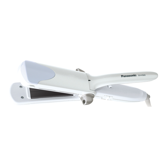
Panasonic EH-HS60 Service Manual
Ion straightener
Hide thumbs
Also See for EH-HS60:
- Operating instructions manual (21 pages) ,
- Operating instructions manual (20 pages) ,
- Operating instructions manual (22 pages)
Quick Links
TABLE OF CONTENTS
1 Warning -------------------------------------------------------------- 2
2 Specifications ----------------------------------------------------- 2
3 Troubleshooting Guide ----------------------------------------- 3
4 Disassembly and Assembly Instructions ---------------- 4
5 Wiring Connection Diagram ---------------------------------- 6
6 Schematic Diagram ---------------------------------------------- 7
7 Exploded View and Replacement Parts List ------------ 8
Model No.
Asia
Middle East
PAGE
© Panasonic Electric Works (Thailand) Co., Ltd.
2009. All rights reserved. Unauthorized copying and
distribution is a violation of law.
Order Number PEWT0911A80CE
Ion Straightener
EH-HS60
PAGE

Summary of Contents for Panasonic EH-HS60
-
Page 1: Table Of Contents
5 Wiring Connection Diagram ---------------------------------- 6 6 Schematic Diagram ---------------------------------------------- 7 7 Exploded View and Replacement Parts List ------------ 8 © Panasonic Electric Works (Thailand) Co., Ltd. 2009. All rights reserved. Unauthorized copying and distribution is a violation of law. -
Page 2: Warning
1 Warning Caution: • Pb free solder has a higher melting point that standard solder; Typicall the melting point is 50 - 70°F (30 - 40°C) higher. Please use a soldering iron with temperature control and adjust it to 750 ± 20°F (400 ± 10°C). In case of using high temperature solder- ing iron, please be careful not to heat too long. -
Page 3: Troubleshooting Guide
3 Troubleshooting Guide... -
Page 4: Disassembly And Assembly Instructions
4 Disassembly and Assembly Instructions 4.1. Disassembly Instructions 1. Remove the electrification board from main body. 4. Remove the discharge cover from main body. 2. Unfasten the tapping screw and the torx screw. 5. Unfasten the tapping screw. 3. Remove the housing A cover by loosing two hooks. 6. - Page 5 7. Remove the discharge cover with shaft from main body. 10. Remove the steam iron cover from Main body by loosing hooks. 11. Put the discharge holder into the main body then remove the lever from main body. 8. Remove the discharge cover from shaft by loosing two hooks, and remove the discharge holder from shaft.
-
Page 6: Wiring Connection Diagram
5 Wiring Connection Diagram... -
Page 7: Schematic Diagram
6 Schematic Diagram 6.1. For 220-240V 6.2. For 110V... -
Page 8: Exploded View And Replacement Parts List
7 Exploded View and Replacement Parts List Model No. : EH-HS60 Exploded View... - Page 9 Model No. : EH-HS60 Parts List Ref. Safety Part No. Part Name & Description Q'ty Remarks EHHS60HSAW1W HOUSING A 1 (For TAIWAN) EHHS60HSAW2W HOUSING A EHHS60HSAW7W HOUSING A 1 (For KOREA) EHHS60SICWW STEAM IRON COVER EHHS60HSBWW HOUSING B EHHS60DICWW DRY IRON COVER...
- Page 10 Model No. : EH-HS60 Parts List Ref. Safety Part No. Part Name & Description Q'ty Remarks EHHS6061501W INDIVIDUAL PACKAGE 1 (For INDIA, VIETNAM, IRAN) EHHS6067501W INDIVIDUAL PACKAGE 1 (For KOREA) EHHS6066501W INDIVIDUAL PACKAGE 1 (For SAUDI ARABIA) EHHS6068501W INDIVIDUAL PACKAGE...


