HP 8340B Manual
Synthesized sweeper (including options 001, 004, 005,006, and 007)
Hide thumbs
Also See for 8340B:
- Manual (530 pages) ,
- Operating instructions manual (119 pages) ,
- Operating manual (14 pages)
Table of Contents
Quick Links
This manual applies directly to the HP 8340B Synthesized
Sweeper having a serial number prefix of 2624A and the HP8341B
Synthesized Sweeper prefixed 2624A.
For additional information about serial numbers, refer to
INSTRUMENTS COVERED BY THE MANUAL in Section I.
•
•
o
CopyrIght
1400 POUNTAINGROvE PARKWAY, SANTA ROSA, CA 95401 U.S.A.
MANUAL PART NO. 06340-90243
Number
Microfiche Part
06340-90244
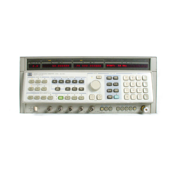
HP 8340B
SYNTHESIZED SWEEPER
(Including Options 001, 004,
005,006, and 007)
HP 8341B
SYNTHESIZED SWEEPER
(Including Option 004)
SERIAL NUMBERS
Manual Changes Supplement Print Date: 18 MAY 1988 Rev. 8
Change 1 documents serial number prefix 2634A.
Change 2 documents serial number prefix 2643A.
Change 3 documents serial number prefix 2650A.
Change 4 documents serial number prefix 2730A.
Change 5 documents serial number prefix 2802A.
Change 6 documents serial number prefix 2804A.
Change 7 documents serial number prefix 281 2A.
Change 8 documents serial number prefix 281 9A.
HEWLETT-PACKARD COMPANY
1986
Printed: AUGUST 1986
HEWLETT
K4~3
PACKARD
Chapters
Table of Contents

Related Manuals for HP 8340B


Summary of Contents for HP 8340B
- Page 1 HP 8341B SYNTHESIZED SWEEPER (Including Option 004) SERIAL NUMBERS This manual applies directly to the HP 8340B Synthesized Sweeper having a serial number prefix of 2624A and the HP8341B Synthesized Sweeper prefixed 2624A. For additional information about serial numbers, refer to INSTRUMENTS COVERED BY THE MANUAL in Section I.
- Page 2 Company will, at its option, either repair or replace products which prove to be defective. For warranty service or repair, this product must be returned to a service facility designated by HP. Buyer shall prepay shipping charges to HP and HP shall pay shipping charges to return the product to Buyer.
- Page 3 “Copyright Hewlett-Packard Company (HP). Reproduced with liP permission. Hewlett-Packard makes no warranty of any kind with regard to this material, including, but not limited to, the implied warranties of merchantability and fitness for a particular purpose.
-
Page 4: Table Of Contents
HP 8341 B) 4-37 5-5. 20/30 Loop Phase Lock, A36, A38, 4-8. Spurious Signals Test, 22 to 26.5 GHz A39, A40, and A43 5-27 (Applies only to HP 8340B) 4-41 5-6. YO Pretune DAC, A54 5-37 4-9. Single Sideband Phase Noise 4-45 S-7. -
Page 5: Section Iv Performance Tests
Section IV: Performance Tests INTRODUCTION The procedures in this section test the HP 8340B and HP 8341B’s electrical performance using the specifications given in Section I as the performance standards. These tests are intended for use in incoming inspection, calibration verification, and post-repair performance verification. All tests can be performed without access to the interior of the instrument. - Page 6 1. This test is not applicable to instruments equipped with Option 006, Delete Pulse Modulation. 2. This is not a Performance Test. It is included as an additional aid to determine that the HP-lB circuitry is operating properly. HP 8340B/41B...
- Page 7 HP 8566A or Spectrum Analyzers HP 8566B Frequency Range: HP 8340B DUT: 0.01 to 22 GHz HP 8341 B DUT: 0.01 to 20 GHz Must have External Time Base Input Center Frequency Accuracy in 0 Hz Span: Same as Time Base Accuracy Minimum Resolution Bandwidth: :=300Hz Residual FM: <100 Hz...
- Page 8 Signal Generator HP 8654A RF Output Power: =0 dBm (or HP 8340B/41B) Settability: to within ±50 kHz HP 236, 226, and 216 are equivalent to the HP HP-I B Desktop Computer HP 236 9836, 9826, and 9816 respectively. Of the three, HP 226 the HP 236 (9836) is suggested.
- Page 9 Maximum Input Power: 100mW P, A, T 1250-1744 Adapters APC-3.5 (f) to Type N (in) (2 required for HP 8340B/41 B) (3 required for HP 8341B with FM) 5061-5311 P, A, T APC-3.5 (f) to APC-3.5 (f) (2 required for HP 8340B)
- Page 10 Table 4-2. Recommended Test Equipment (4 of 5) Use 1 Instrument Critical Specifications Recommended Model HP Part No. PC Board Extenders 24-pin 08340~600952 30-pin 08505~600412 36-pin 08505~600422 44-pin 08350~600312 48-pin 08340~600502 62-pin 08340~600962 110-pin 08340~600332 IC Test Clip 16-pin 1400~07342...
- Page 11 3. For best accuracy in the Pulse Modulation Rise and Fall Time and the Amplitude Modulation Performance Tests, the Local Oscillator drive to the mixer should be =-~-4 dBm. The HP 8340A/B Option 001, used as the LO will produce +4 dBm at any frequency. Any HP 8341A/B will provide sufficient power at all frequencies, but may be used only with an HP 8341A/B OUT.
-
Page 12: Internal Time Base Aging Rate
Frequency Standard Oscilloscope 1 HP 1741A 1. A 50 Ohm Feedthrough Termination Isuch as the HP 101 OOC) is required when using an oscilloscope without a 50 Ohm input, It is not required with the HP 1741A. HP 8340B/41B Performance Tests... - Page 13 AC power for 24 hours before proceeding. Procedure 1. Connect the equipment as shown in Figure 4-1. Adjust the oscilloscope external triggering controls for a stable display of the HP 8340B/41B 10 MHz REF OUTPUT signal. 360 degrees. Record the time (Ti) in seconds.
- Page 14 6. Verify that the aging rate is less than per day. NOTE If the absolute frequencies of the frequency standard and the HP 8340B/41B Time Base oscillator are extremely close, the measurement time in steps 3 and 4 (Ti and T3) can be reduced by measuring the time required for a phase change of less than 360 degrees.
-
Page 15: Frequency Range And Cw Mode Accuracy
Accuracy: Same as Time Base Accuracy in the specifications portion of Section I. Description The HP 8340B/41B RF output is supplied to a frequency counter. The frequency counter internal time base is used as the reference for the DUT to eliminate time base error from the measurement. The DUT frequency display and the counter display should agree, within the resolution of each instrument. - Page 16 Check the high frequency endpoint. FOR HP 8340B Connect the HP 8340B RF output to the 500 MHz-26.5 GHz counter input. Press the HP 8340B [CW] key and enter [2] [6] [5] [GHz].Press [POWER LEVEL] [0] [dBm]. The counter should 26.5 GHz ±4Hz...
- Page 17 Press the [CW] key to display the CW frequency in the [ENTRYDISPLAY]. b. Using the down arrow key, step down to 2 300.000000 MHz. Check the counter indication at each step. The counter should indicate the HP 8340B/41 B frequency 1 Hz z the resolution ±...
- Page 18 5 kHz steps which steps the 20/30 frequency from 30 MHz down to 29.990 MHz in 1 kHz steps. Since the M/N fre- quency remains constant and the HP 8340B/41B output frequency is mixed with a harmonic (13th) of the M/N signal and the resultant output is phase compared to the 20/30 output, the DUT output frequency must increase by 1 kHz/step to satisfy the 20/30 phase lock loop.
- Page 19 The counter should indicate the DUT CW frequency ± 1 Hz ± the resolution of the counter. NOTE The above steps program the 20/30 frequency from 20.13 up to 21.03 in 0.1 MHz steps and checks additional Ni Divider programming bits. HP 8340B/41B Performance Tests 4-17...
- Page 20 8. If frequency errors occurred, the instrument requires service. To troubleshoot the instrument, determine what frequency related circuit is most likely to have caused the symptom (i.e., M/N Loop or 20/30 Loop) VIII of the Service Manual (may be ordered separately). then refer to Section lIP 8340B/41B 4-18 Performance Tests...
-
Page 21: Sweep Time Accuracy
Description The HP 8340B/41 B is swept from 3 GHz to 7 GHz at 5 different sweep times, ranging from 10 ms to 50 sec. The rear panel STOP SWEEP IN/OUT signal of the DUT is used to trigger INPUT A and B on an HP 5316A Universal Counter used in the time interval mode. - Page 22 HP 5316A in step 4, allow the DUT to complete at least three sweeps. 4. On the HP 8340B/41B, press [SWEEP TIME] [1] [0] [msec]. Verify that the sweep time displayed by the HP 5316A is within the limits shown in Table 4-6.
-
Page 23: Swept Frequency Accuracy
CRT. The HP 8340B/41B can now be set to sweep any frequency range and the oscilloscope center grati- cule line will represent the calibrated percentage (e.g., 20%) of the sweep range. The spectrum analyzer center frequency is set to a frequency that is the desired percentage (e.g., 200/0) of the DUT... - Page 24 Stop Mode, only Start/Stop Mode swept frequency accuracy is tested. NOTE The spectrum analyzer resolution bandwidth and DUT sweep time must be compatible to obtain the desired oscilloscope response. OSCI LLOSCOPE Figure 4-4. Swept Frequency Accuracy Test Setup 4-22 Performance Tests HP 8340B/41B...
- Page 25 GHz for 20% (4 GHz for 50%, or 4.6 GHz for 80%). Set FREQUENCY SPAN to zero. Set RES BW (resolution bandwidth) to 3 MHz. 4. Set HP 8340B/41B to have a sweep out voltage and at the same time, a phase locked CW frequency that is proportional to a percentage of band as follows:...
- Page 26 4-4. SWEPT FREQUENCY ACCURACY (Cont’d) 7. Refer to Table 4-8, press the HP 8340B/41B [STARTFREQ] key and enter the start frequency shown in Table 4-8. Press the [STOPFREQ] key and enter the appropriate stop frequency. Press the [SWEEPTIME] key and enter the appropriate sweep time. Select the appropriate spectrum analyzer resolution bandwidth.
-
Page 27: Maximum Leveled Output Power And Power Accuracy Test
(Rear Panel Output w/o Atten.) ±18 to ±lOdBm3 ± 1.8dB + 22dB ±lOto—10 dBm ± 1.0 dB ± 1.S dB + 1.9dB —10 to —20 dBm ± 1.8 dB ± 2.3 dB + 2.7 dB Performance Tests 4-25 HP 8340B/41B... - Page 28 +09dB NOTES 1. Applies only to HP 83408 2. Internally leveled, AM off. The POWER dBm display monitors the actual output power, giving accurate readings when unleveled, externally leveled, or when amplitude modulating with a signal that has a dc component. The ENTRY DISPLAY shows the desired power level, or the desired external detector output voltage, exclusive of modulation.
- Page 29 Two different Power Sensors may be required to cover the complete frequency range. The HP 8481A Power Sensor is used from 10 MHz to 50 MHz and the HP 8485A Power Sensor is used for the other frequency bands covering 50 MHz to maximum output frequency of the DUT. The 8485A Power Sensor can be used down to 10 MHz, but if a minimum or maximum that is close to the test limits occurs in this frequency range, the 8481A Power Sensor should be used.
- Page 30 3. Press the [POWERLEVEL] key and, using the front panel rotary knob, increase the power level until the UNLEVELED indicator comes on. Slowly decrease the power level until the UNLEVELED indicator just goes off. Note the ENTRY DISPLAY power indication. 4-28 Performance Tests HP 8340B/41B...
- Page 31 10 dB and the ALC is set to 0 dBm). If the power meter indication is >0.1S dB from the ENTRY DISPLAY indication, refer to the ALC adjustments in Section V (in the Service Manual). Performance Tests 4-29 HP 8340B/41B...
- Page 32 Table 4-10. NOTE For Band 0 (10 MHz to 2.3 GHz), if the minimum or maximum power occurred below 50 MHz, use the HP 8481A Power Sensor to measure the power level. [Ml] and, using the rotary knob, change 15.
- Page 33 Flatness: Maximum Minimum (=2.2 dB, Standard) (=2.6 dB, Option 004) (=1.8 dB, Option 001) (=2.2 dB, Option 005) (Applies to the HP 8340B only) Frequency Range: 20.0 0Hz to 26.5 GHz Power Meter HP 834GB Indication Entry Display Step 14...
-
Page 34: External Leveling
The HP 8340B/41B’s external leveling circuit allows a positive or negative crystal detector to be used in the external leveling loop. A negative crystal detector (HP 8473C) is used in this test but a crystal detector may be substituted. - Page 35 Digital Voltmeter Crystal Detector HP 8473C Capacitor (1000 pF) HP P/N 0160-4574 Adapters APC 3.5 (f) to APC 3.5 (f) HP P/N 5061 -5311 required if DUT is HP 83408) TYPE N to APC 3.5 (in) HP P/N 1250-1 744...
- Page 36 —33.70 —40 —9.24 —10.00 —10.79 Table 4-14. External Leveling Limits (With 20 dB Attenuator) DVM Indication (my) Selected Lower Limit Ideal Upper Limit —50 —2.785 —3.162 —3.550 —60 —0.744 —1.000 —1.259 —66 —0.273 —0.501 —0.731 4-35 Performance Tests HP 8340B/41B...
- Page 37 —0.7079V —49 —3.548mV —4 —0.6310V —50 —3.162mV —5 —0.5623V —51 —2.818mV —6 —0.5012V —59 —1.122mV —7 —0.4467V —60 —1.OOOmV —8 —0.3981V —61 —0.8913mV —9 —0.3548V —65 —0.5623mV —10 —0.3162V —66 —0.5012mV —11 —0.2818V —67 —0.4467mV HP 8340B/41B 4-36 Performance Tests...
-
Page 38: Spurious Signals Test
Offset> 1 kHz from carrier 1. Band 4 applies to HP 83400 only. )escription ~he HP 8340B/41B RF output signal is displayed on a spectrum analyzer to verify that the harmonic and non- armonic spurious signals are at or below the specified level. Equipment... - Page 39 4-7. SPURIOUS SIGNALS TEST (10 MHz to 22 GHz HP 8340B only) (10 MHz to 20 GHz HP 8341 B) SPECTRUM ANALYZER SEMI—RIGID CABLE Figure 4-7. Spurious Signals Test Setup (10 MHz to 22 GHz HP 8340B) (10 MHz to 20 6Hz...
- Page 40 Press the [STARTFREQI key and enter the start frequency for the next frequency band. Repeat steps 3 through 8 until all DUT frequency bands have been tested up to 22 GHz (for HP 8340B), or 20 GHz (for HP 8341 B).
-
Page 41: Spurious Signals Test, 22 To 26.5 Ghz (Applies Only To Hp 8340B)
4-8. SPURIOUS SIGNALS TEST, 22 to 26.5 GHz (Applies only to HP 8340B) NOTE Non-harmonically-related spurious responses, resulting from mixing products produced by two or more signals within the HP 8340B, follow a mathematical relationship to the signals that generated them. If the level of all such signals up to 22 GHz are within the specification, then no mixing products will be out of specification above 22 GHz. - Page 42 Description The HP 8340B Under Test RF output signal is fed through a 20 dB pad and a high pass filter and is then down converted using a mixer and an HP 8340A/B as a Local Oscillator. the mixer output is fed to a low frequency spectrum analyzer.
-
Page 43: Equipment
4-8. SPURIOUS SIGNALS TEST, 22 to 26.5 GHz (Applies only to HP 8340B) (Cont’d) Equipment Local Oscillator HP 8340A/B Opt. 001 20 dB Attenuator HP 8493C Opt 020 High Pass Filter (Made from the following adapters)l APC 3.5 (f) to Waveguide HP K281C APC 3.5 (in) to Waveguide... -
Page 44: Single Sideband Phase Noise
PHASE NOISE CALCULATION. A second HP 8340A/B or HP 8341A/B is used as a local oscillator (LO) to mix down the microwave frequency from the HP 8340B/41B under test (DUT) to a 1 MHz IF. The IF signal is amplified and, for 30 Hz, 100 Hz and 1 kHz offsets, sent directly to a low frequency spectrum analyzer (HP 3585A). - Page 45 13.402,19.S02 and, in the case of the HP 8340B, 26.032 GHz. These specific frequencies typically have the worst case phase noise for the HP 8340B/41B. The DUT is adjusted for the test frequency and then the LO frequency is adjusted to obtain a 1 MHz signal to noise level (IF to 0.9 Hz IF.
-
Page 46: To Apc 3.5 (F)
It is important that the mixer be connected directly to the LO’s RF Output connector. Procedure 1. Connect equipment as shown in Figure 4-9 with the amplifier connected directly to the HP 3585A 50 Ohm input. NOTE The foam pads shown in Figure 4-9 are required to isolate the DUT and LO from mechanical vibrations which could induce phase noise. - Page 47 12. Reduce LO frequency by 30 Hz (IF 1.00003 MHz ±0.9Hz). 13. Allow one sweep of the HP 3585A to occur. Adjust the HP 3585A marker to the peak of the IF. Record the marker power level (Cal Data) into Table 4-19.
- Page 48 LO for an HP 3585A COUNTER reading of 1 MHz ±0.9Hz. 25. On the HP 3585A, press FREQUENCY SPAN, 250 Hz, RES 8W, 3 Hz. Step the RANGE until the overload light just turns on and then increment it one step. Allow one sweep to occur.
- Page 49 32. Connect the equipment in Figure 4-9 with the 1 MHz Notch Filter connected. Select the 1 MOhin input impedance on the HP 3585A. 33. On the HP 3585A, press FREQUENCY SPAN, 2S kHz, RES 8W, 100 Hz. Decrement the RANGE until the overload light just turns on and then increment it one step.
- Page 50 0 for 30 Hz, 100 Hz, and 1 kHz offsets value measured in step 22 (see Table 4-19) for 10K and 100 kHz offsets 2. Applies only to HP 8340B. 3. Not applicable to instruments equipped with Option 007, Relaxed Phase Noise Specifications.
-
Page 51: Power Sweep Test
Power Sweep Width and Linearity: See Figure 2 in the HP 8340B/41B specification table. In normal operation (a) the ALC does not operate below —9.9S dBm (see Figure 3 in the HP specification table), and so the maximum power sweep range is the difference of —9.95... - Page 52 (in) (1 required if DUT is HP 8341 B) Procedure 1. Connect equipment as shown in Figure 4-10. Connect the HP Power Sensor to the Power 8485A Meter. Allow a one hour warm up time. Set the Power Meter’s calibration switch to include 1 GHz, then zero and calibrate the Power Meter before connecting the Power Sensor to the DUT.
- Page 53 The 50 ohm termination on the DUT’s PULSE input simulates the RF OFF state when PULSE is selected (ON). The difference between the two spectrum analyzer displayed levels is the pulse ON/OFF ratio. HP 8340B/418 SPECTRUM ANALYZER UNDER TEST TERMINATION ADAPTER APC—3.
-
Page 54: Pulse Modulation On/Off Ratio Test
4. Press the DUT’s [PULSE]key (ON). The spectrum analyzer marker delta amplitude level should be greater than 80 dB. S. Repeat steps 2 through 4 at CW frequencies of 3, 9,15, and, if the DUT is an HP 8340B, 22 GHz. NOTE For further verification of the ON/OFF Ratio, steps 2 through 4 may be repeated for other frequencies of interest. -
Page 55: Pulse Modulation Rise And Fall Time Test
Refer to Figure 4-12 Pulse Definitions. TRF -RF Pulse Length TR -RE Pulse Rise Time TV -Input Pulse Length TF -RE Pulse Fall Time 0 -Delay Time VOR.Overshoot and Ringing Vp -RF Pulse Amplitude -Video Feedthrough Figure 4-12. Pulse Definitions HP 8340B/41B Performance Tests 4-57... - Page 56 HP 1741A Adapters APC 3.S (f) to APC 3.S (f) HP P/N S061-5311 (1 required if DUT is HP 8340B) Type N (in) to APC 3.5 (f) HP P/N 1250-1 744 (1 required if DUT is HP 8341 B) Type N (in) to APC 3.5...
- Page 57 1. Connect equipment as shown in Figure 4-13. Connect the mixer directly to the local oscillator RF output to obtain maximum LO drive to the mixer. Connect the BNC tee directly to the HP 8340B/41B PULSE IN connector. Allow a one hour warm up time.
- Page 58 3. Set both oscilloscope channels A and B for SO ohm input. Set the oscilloscope to view the pulse generator output waveform. Adjust the HP 8012B pulse width VERNIER for a 100 nanosecond pulse. Adjust the pulse period VERNIER for a 10 microsecond period.
- Page 59 8. The 10% point should be <2S nanoseconds (S divisions) from the 90% point. 9. Repeat steps 5 through 8 at CW frequencies of 3, 9,15, and, if the DUT is an HP 8340B, 22 GHz. Set the LO CW frequency to be 50 MHz below the DUT’s frequency.
-
Page 60: Pulse Modulation Accuracy Test
~0.3 dB --0.3 dB =500 ns 1. Band 41>20.0 to 26.5 GHz) only applies to the HP 8340B. 2. -i-15 to ~-55~C.Duty Cycle must be >0.010/0 Description The DUT’s RF output frequency is down converted to 50 MHz using a mixer and a local oscillator. The 50 MHz IF signal is amplified and applied to an oscilloscope. - Page 61 HP P/N 5061-5311 (1 required if DUT is HP 8340B) to APC 3.5 (f) Type N (in) HP P/N 1250-1744 (1 required if DUT is HP HP 8341 B) to APC 3.5 Type N (in) (in) HP P/N 1250-1 743...
- Page 62 5. Set the oscilloscope horizontal for 50 nanoseconds/division and select channel A input only. Adjust the channel A (IF carrier input signal) vertical sensitivity to view the entire RF envelope. LOCAL HP 8340B/410 OSCI LLATOR UNDER TEST Figure 4-16. Pulse Modulation Accuracy Test...
- Page 63 11. Set the pulse generator period to 10 microseconds and pulse width to 100 nanoseconds. Repeat steps 5 through 10 at CW frequencies of 3, 9, 15, and, if the DUT is an HP 8340B, 22 GHz. Set the LOs CW frequency to be 50 MHz below the DUT’s frequency. For DUT frequencies of iS and 22 GHz, press [PEAK] to ON.
-
Page 64: Pulse Modulation Video Feedthrough Test
<5% for output power levels =-i-8dBm to 26.5 GHz (Bands =0.2% 1~4)1: 1. Band 4 (>20.0 to 26.5 GHZ) only applies to the HP 8340B. Description NOTE Video feedthrough is any component of the pulse generator signal that appears at the DUT’s RF output connector. - Page 65 HP 8340B/41B UNDER TEST MA I N TRIGGER EXT TRIG INPUT Figure 4-17. Pulse Modulation Video Feedthrough Test Setup 2. Set up the HP 8012B Pulse Generator at follows: — PERIOD slide switch lj.t .lin PULSE TRANSITION TIME slide switch...
- Page 66 3. Set both oscilloscope channels (A and B) to 50 Ohm input. Set the oscilloscope to view the pulse generator output waveform. Adjust the HP 8012B pulse width VERNIER for a 100 nanosecond pulse. Adjust the pulse period VERNIER for a 100 microsecond period. Adjust the amplitude VERNIER for about a 3V pulse amplitude (TTL level).
- Page 67 11. Select the oscilloscope XS vertical magnifier. The test limit is now 0.2 mV or 1 minor division on the oscilloscope. 12. Select several CW frequencies >2.3 GHz. and verify that the video feedthrough is less than 1 minor division on the oscilloscope. HP 8340B/41B 4-70 Performance Tests...
-
Page 68: Amplitude Modulation Test
The following specifications apply when the HP 8340B/41B are internally leveled, for waveforms whose envelope peak is at least 1 dB below maximum specified power. Unless noted pulse modula- tion must be OFF; however, the HP 83408/418 are capable of simultaneous amplitude and pulse modulation. See Section III, Operation. - Page 69 HP P/N 5061 -5311 (1 required if DUT is HP 8340B) Type N to APC 3.5 (f) HP P/N 1250-1 744 (in) (1 required if DUT is HP HP 8341 B) Type N HP P/N 1250-1 743 to APC 3.S (in) (in)
- Page 70 —2.91 dB — 20 log (1 + (—0.3 + (0.05 times —0.3))) —3.29 dB NOTE The DUT’s test power levels are selected to avoid power meter range changes at the +30 and —30% modulation settings. Performance Tests 4-73 HP 8340B/41B...
- Page 71 Increase the function generator output amplitude to obtain >90% modulation depth. 16. Repeat steps 11 through iS at DUT RF frequencies of 3, 9,15, and, if the DUT is an HP 8340B, 22 GHz. Make sure LO CW frequency is always 50 MHz below the DUT frequency.
-
Page 72: Fm Accuracy And Flatness
Adapters: APC 3.5(f) to TYPE N(in) HP P/N 12S0-1744 (1 required if DUT is HP 8340B) (2 required if DUT is HP 8341 B) APC 3.S (f) to APC 3.S (f) HP P/N S061-S311 (1 required if DUT is HP 834GB) - Page 73 2. Set the function generator to a 100 kHz sine wave. Set the DVM to ac volts. 3. Press [INSTRPRESET] on the DUT and set up the following conditions: Sweep Mode: Frequency out: 2.2 GHz Leveling: RF Output: 0 dBin RF Peaking (PEAK): Sensitivity: 1 MHz/V (default condition) 4-76 Performance Tests HP 8340B/41B...
- Page 74 9. Repeat steps 4 through 8 at CW frequencies of 2.5, 6.9, 13.4,18 and 20 GHz (20 GHz applies to the 8340B only). After entering a new CW frequency, press the FM key twice to display the FM sensitivity in the DUT’s ENTRY DISPLAY and then press the DUT’s DOWN ARROW key to select an FM sensitivity of 1 MHz/V.
- Page 75 (this will be explained in the procedure). The output of the discriminator is fed to the SO Ohm input of an HP 3585A spectrum analyzer. By using the tracking generator output to drive the FM input of the DUT, a swept response of FM Flatness will be seen on the spectrum analyzer CRT.
- Page 76 1. Refer to Figure 4-21, FM Flatness Setup. Connect the test equipment as shown. Connect the output of the HP 8447F to the SO Ohm input of the HP 3585A. The HP 3585A should not be connected to the mixer at this time.
- Page 77 6. Press [RECALL][1] on the HP 3585A. Make sure the DUT is set to the desired CW frequency. Move the output of the HP 8447F to the DUT’s AM input. Connectthe output of the mixer to the HP 3585A SO Ohm input.
- Page 78 HP 8340B, also perform the following: Press [CW] [2] [0] [GHz]. Repeat steps 6 If testing through 13. iS. Repeat Steps 6 through 14 with the HP 355D step attenuator set to SO dB. When repeating step 10, set the FM sensitivity to 10 MHz/V, not 1 MHz/V. Performance Tests...
-
Page 79: Hp 8340B/41B Hp-Lb Operation Verification Test
Description The test program given in Table 4-32 is written to verify the HP 8340B/41B HP-lB interface by writing to and reading from the instrument. The program also displays the DUT’s status bytes similar to the format shown in Table 4-31, HP 8340B/41B Status Byte Descriptions. Upon running the program the... - Page 80 Connect the equipment as shown in Figure 4-22. Enter the program shown in Table 4-32 if the HP 8SF is used, or the program in Table 4-33 if the HP 9826A or 9836A is used. Press the RUN key. The program will display the DUT’s status bytes similar to Table 4-31. After the program goes through the output loop routine about two times, all status bits should be “0”...
- Page 81 4-17. HP 8340BI41B HP-lB OPERATION VERIFICATION TEST (Cont’d) Table 4-31. HP 8340B/41B Status Byte Description STATUS BYTE (#1) BIT# DECIMAL VALUE SRO on SRQ on SRO on RE SRO on FUNCTION REOUEST SRO on SRO on SRO on End of...
- Page 82 Table 4-32. HP 8340B/41B HP-lB Operation Verification Programming Listing (For Use with HP 8SF) HP 8340B/41B HP-LB OPERATION VERIFICATION VERIFICATIONTEST 15MARCH86 I1=~719 OUTPUT Ii ;“IPS2TSTS” ON KEY# 1 ,“SYNTAX” GOSUB 370 ONKEY#4,DATABITGOSUB400 LOCAL7 OUTPUT Ii ;“OS” DJSP “HP 8340B/41B STATUS BYTE lAND 2”...
- Page 83 Table 4-33. HP 8340B/41B HP-lB Operation Verification Programming Listing (For Use with HP 9826A/36A) HP8340B/41BHP-IBOPERATION VERIF ICATION TEST 15MARCH86 11=719 OUTPUT Ii ;“IP 62 TSTS” OFF KEY ON KEY 1 LABEL “SYNTAX” GOTO Syntax ON KEY 4 LABEL “DATA BIT” GOTO Data..bit LOCAL 7 OUTPUT 1;...
- Page 84 HP 8340B/41B Test Record Card (1 of 30) Hewlett-Packard Model 8340B/41 B Date: Synthesized Sweepers Model Number: Serial Number: Tested By: Step Measured Upper SPECIFICATIONS TESTED TEST Lower Value Limit Limits Conditions Limit 4-1. Internal Time Base Aging Rate = Time for 360 degree...
- Page 85 HP 8340B/41B Test Record Card (2 of 30) Lower Measured Upper SPECIFICATIONS TESTED TEST Limit Value Limit Limits Conditions 4-2. Frequency Range and cw Mode Accuracy Frequency Range Check 10 MHz Freq. ~1 Hz ±Counter Resolution 20.0 GHz (HP 8341 B) Freq.
- Page 86 HP 8340B/41B Test Record Card (3 of 30) Lower Measured Upper SPECIFICATIONS TESTED TEST Step Limit Value Limit Limits Conditions 4-2. Frequency Range and cw Mode Accuracy (cont’d) M/N Divider Check Freq. ±1 Hz ± Counter (N Divider) Resolution M=27...
- Page 87 HP 8340B/41B Test Record Card (4 of 30) SPECIFICATIONS TESTED TEST Lower Measured Upper Step Limits Conditions Limit Value Limit Frequency Range and cw 4-2. Mode Accuracy (Cont’d) 20-30 Loop Check (N2 Divider) DUT ENTRY DISPLAY DUT START Frequency Freq.
- Page 88 HP 8340B/41B Test Record Card (5 of 30) Lower Measured Upper SPECIFICATIONS TESTED TEST Step Limit Value Limit Limits Conditions Frequency Range and 4-2. Mode Accuracy (Cont’d) 20-30 Loop Check (Ni Divider) DUT ENTRY DISPLAY Frequency Counter Indicator Freq. Counter ±1Hz...
- Page 89 HP 8340B/41B Test Record Card (6 of 30) Lower Measured Upper SPECI FICATIONS TESTED TEST Limit Value Limit Limits Step Conditions 4-3. Sweep Time Accuracy 9.5 ms 10.5 ms 10 milliseconds 100 milliseconds 0.95s 1.OSs 1 second 9.S s 10.S s 10 seconds 47.S s...
- Page 90 ± 50000 5.0804 5.1804 5.1304 16.452 ± 5.89 50000 5.84 ± 20.0 5.79 6.70 6.75 50000 6.80 ± 24.551 50000 7.09 7.19 7.14 ± 26.51 1. Perform this step only when testing an HP 8340B. Performance Tests 4-95 HP 8340B/41B...
- Page 91 5.350 5.300 -‘-50000 5.250 1-50000 9.426 16.452 9.376 9.326 --50000 11.2 20.0 11.15 11.1 ±50000 13.425 13.375 24.551 13.475 50000 14.35 14.45 26.51 14.4 ± 1. Perform this step only when testing an HP 8340B. HP 8340B/41B 4-96 Performance Tests...
- Page 92 7.05 ± 13.6716 13.5716 13.6216 iSOOOO 16.452 14.21 50000 20.0 14.11 ± 14.16 20.1 50000 20.05 20.15 ± 24.551 21.61 21.66 50000 21.71 ± 26.51 1. Perform this step only when testing an HP 83408. Performance Tests 4-97 HP 8340B/41B...
- Page 93 HP 8340B/41B Test Record Card (10 of 30) Step TEST Lower Measured Upper SPECIFICATIONS TESTED Conditions Limit Value Limit Limits Maximum Leveled Output 4-5. Power and Power Accuracy Maximum Leveled Power Band 0 ENTRY DISPLAY Power Indication ____dBm Continuous Sweep, Auto Sweep Time...
- Page 94 HP 8340B/41B Test Record Card (11 of 30) SPECIFICATIONS TESTED TEST Lower Measured Upper Limits Step Conditions Limit Value Limit Maximum Leveled Output 4-5. Power and Power Accuracy (Cont’d) Maximum Leveled Power Band 2 ENTRY DISPLAY Power Continuous Sweep, Auto Sweep...
- Page 95 (F.P. Out with Atten.) +4 dBm Option 001 (F.P. Out No Atten.) —1 dBm Option 004 (R.P. Out with Atten.) +2 dBm Option 005 (R.P. Out No Atten.) 1. Perform this step only when testing an HP 8340B. 4-100 Performance Tests HP 8340B/41B...
- Page 96 Band 4 Measurement Minimum Power Frequency M2 Frequency Minimum Power Level M2 Power Level Maximum Power Frequency Ml Frequency Maximum Power Level Ml Power Level 1. Perform this step only when testing an HP 8340B. Performance Tests 4-101 HP 8340B/41B...
- Page 97 =1.8 dB (Option 001) =2.2 dB (Option 005) Band 4 Calculation 1 =3.2 dB (Standard) =3.6 dB (Option 004) =2.6 dB (Option 001) =3.0 dB (Option 005) 1. Perform this step only when testing an HP 8340B. HP 8340B/41B 4-102 Performance Tests...
- Page 98 HP 8340B/41B Test Record Card (15 of 30) Lower Measured Upper SPECIFICATIONS TESTED TEST Step Limit Value Limit Conditions Limits 4-6. External Leveling (Using Negative Crystal Detector) Leveling Voltage (dBv) —1.883V —2.114V —0.944V —1.059V —0.2983 V —0.3352 V —10 —0.0942 V —20...
- Page 99 HP 8340B/41B Test Record Card (16 of 30) Step Lower Measured Upper SPECIFICATIONS TESTED TEST Limit Value Limit Limits Conditions 4-7. Spurious signals (10 MHz to 22 GHz - HP 534GB) (10 MHz to 20 GHz - HP 83415) Frequency of Interest Selected...
- Page 100 <—97 dBc ______ 26.032 GHz 1 <—52 dBc 30Hz Offset ______ <—S8 dBc 100 Hz <—66 dBc ______ <—74 dBc 10kHz ______ <—95 dBc ______ 1. Pertorm this step only when testing an HP 8340B. Performance Tests 4-105 HP 8340B/41B...
- Page 101 26.032 GHz d Bc <—SS dBc Offset 100 Hz d Bc <—63 dBc 1 kHz 10kHz <—71 d Bc ______ <—95 dBc 100 kHz ______ 1. Perform this step only when testing an HP 8340B. HP 8340B/41B 4-106 Performance Tests...
- Page 102 Power Sweep Range Must be =20 dB difference 20 dB 26 GHz Start Level End Level Power Sweep Range Must be =20 dB difference 20 dB t. Perform thia step only when testing an HP 834GB. 4-107 Performance Tests HP 8340B/41B...
- Page 103 25 nsec Fall Time nsec 25 nsec 1. Pertorm this step only when testing an HP 834GB. NOTE Tests 4-11, 4-12, 4-13, and 4-14 do not apply to instruments equipped with Option 006, Delete Pulse Modulation. HP 8340B/41B 4-108...
- Page 104 HP 8340B/41B Test Record Card (21 of 30) SPECIFICATIONS TESTED TEST Lower Measured Upper Limits Step Conditions Limit Value Limit 4-13. Pulse Modulation Accuracy DUT CW Freq. 1 GHz 100 kHz ENTRY DISPLAY Power Level ____dBm Pulse Width 100 ns...
- Page 105 HP 8340B/41B Test Record Card (22 of 30) SPECIFICATIONS TESTED TEST Step Lower Measured Upper Limits Conditions Limit Value Limit Pulse Modulation Accuracy 4-13. (Cont’d) Pulse Repetition Freq. Range 3 GHz DUT CW Freq. Minimum PRF Power Level ENTRY DISPLAY...
- Page 106 HP 8340B/41B Test Record Card (23 of 30) SPECIFICATIONS TESTED TEST Lower Measured Upper Limits Conditions Limit Value Limit Step 4-13. Pulse Modulation Accuracy (Cont’d) DUT CW Freq. = 15 GHz PRF = 100 kHz ENTRY DISPLAY Power Level Pulse Width = 100 ns...
- Page 107 HP 8340B/41B Test Record Card (24 of 30) SPECIFICATIONS TESTED TEST Lower Measured Upper Limits Step Conditions Limit Value Limit 4-13. Pulse Modulation Accuracy (Cont’d) NOTE Perform the following steps only when testing an HP 8340B. Pulse Repetition Freq. Range 8340B CW Freq.
- Page 108 HP 8340B/41B Test Record Card (25 of 30) SPECIFICATIONS TESTED TEST Lower Measured Upper Limits Conditions Limit Value Limit Step 4-14. Pulse Modulation Video Feedthrough DUT CW Freq. = 0.4 GHz Oscilloscope peak voltage Power Level = +8 dBm < 12 mV 0 dBm <5mV...
- Page 109 HP 8340B/41B Test Record Card (26 of 30) SPECIFICATIONS TESTED TEST Step Lower Measured Upper Limits Conditions Limit Value Limit Amplitude Modulation 4-15. AM Sensitivity DUTFreq. 1.5GHz Power —5 dBm Power Meter Indication _____ j-30% Modulation <2.38 dB — >2.18 dB Power Meter Change —30% Modulation...
- Page 110 HP 8340B/41B Test Record Card (27 of 30) SPECIFICATIONS TESTED TEST Lower Measured Upper Limits Conditions Step Limit Value Limit Amplitude Modulation 4-15. (Cont’d) 3 GHz DUT Freq. AM Frequency Response Vrms Note DVM Indication =±0.2 d B Funct. Gen.
- Page 111 HP 8340B/41B Test Record Card (28 of 30) SPECIFICATIONS TESTED TEST Step Lower Measured Upper Limits Conditions Limit Value Limit 4-15. Amplitude Modulation (Cont’d) NOTE Perform the following steps only when testing an HP 8340B. 8340B Freq. = 22 GHz...
- Page 112 HP 8340B/41B Test Record Card (29 of 30) SPECIFICATIONS TESTED TEST Lower Measured Upper Limits Conditions Step Limit Value Limit 4-16. Frequency Modulation ACCU RACY 2.2 GHz CW Freq. FM Sensitivity 1 MHz/V 100/a Error FM Sensitivity 10 MHz/V 100/a Error CW Freq.
- Page 113 3 dB CW Freq. = 18 GHz Worst Case Power Level 3 dB CW Freq. = 20 GHz 1 Worst Case Power Level 3 dB 1. Perform this step only when testing an HP 834GB. HP 8340B/41B 4-118 Performance Tests...
-
Page 114: Section V Adjustments
Adjustments INTRODUCTION This section provides adjustment procedures for the HP 8340B/41B Synthesized Sweepers. These procedures should not be performed as routine maintenance but should be used (1) after replacement of a part or component, or (2) when performance tests show that the instrument’s specifications cannot be met. -
Page 115: Adjustment Tools
ADJUSTMENT TOOLS For adjustments requiring a non-metallic tuning tool, use fiber tuning tool, HP Part Number 871 0-0033. In situations not requiring non-metallic tuning tools, an ordinary small Screwdriver or other suitable tool is sufficient. However, use of a non-metallic adjustment tool possible is recommended. -
Page 116: Procedure To Access Calibration Constants
“protected memory area” by pressing the following key sequence: [SHIFT][MHz] [1] [4] [Hz] [SHIFT][kHz][5] [3] [4] [9] [Hz]Wait “CALIBRATION RESTORED” to be displayed in the ENTRY DISPLAY and then press [INSTR PRESET]. Adjustments HP 8340B/41B... - Page 117 5-67 5-14 Unleveled RE Output Adjustments 5-71 5-15 ALC Adjustments 5-89 5-16 Leveled RE Output Adjustments 5-10 1 5-17 RE Output Power Flatness and Adjustment 5-115 5-18 Pulse Adjustments 5-12 1 5-19 External Module Leveling Adjustment S-129 HP 8340B/41B Adjustments...
- Page 118 Amplifier to 25 MHz passband. Selected to adjust resistance of RLC network at input of A48R22 6.2 - 23.7 Ohms Buffer Amplifier for passband bandwidth of 18 to 32 MHz. The highest Band available with an HP 8341B is Band 3. Adjustments HP 8340B/41B...
- Page 119 A19 Capacitor None Assembly A20 RE Section None Filter A21 Pulse Pulse Adjustment 5-18 Modulator Driver 1. The highest Band available with an HP 8341B is Band 3. 2. Assemblies which are not listed do not require adjustment. Adjustments HP 8340B/41B...
- Page 120 A39C50, A39L4, L16, L17 5-5 steps 32 through 43 Upconverter A40 PLL2 VCO PLL2 Adjustments 5-5, steps 1 through 31 A41 PLL2 Phase None Detector A42 PLL2 Divider None A43 PLL2 PLL2 Adjustments 5-5, steps 1 through 31. Discriminator HP 8340B/41B Adjustments...
- Page 121 A60 Processor None A61 Not Assigned A62 Main Mother None Board A63 90 dB RF Flatness and RF Attenuator Calibration 5-17, steps 1 through 17. For RF Attenuator Attenuator Calibration, see manual supplement titled ‘Automated Test Procedures.” Adjustments UP 8340B/41B...
- Page 122 Table 5-4. HP Part Numbers of Standard Value Components (1 of 4) CAPACITORS RANGE: 1 to 24 pF TYPE: Tubular RANGE: 27 to 680 pF TOLERANCE: TYPE: Dipped Mica lto9.lpF= ±.25pF TOLERANCE: ±5% 10to24pF~= ±5% Value HP Part Number Value...
- Page 123 Table 5-4. HP Part Numbers of Standard Value Components (2 of 4) RESISTORS RANGE: 10 to 464K Ohms TYPE: Fixed Film WATTAGE: .125 at 125 0C TOLERANCE: ±1.0% Value HP Part Number Value HP Part Number Value HP Part Number 21.5K...
- Page 124 Table 5-4. HP Part Numbers of Standard Value Components (3 of 4) RESISTORS RANGE: 10 to 1.47M Ohms TYPE: Fixed Film WATTAGE: .5 at 125 TOLERANCE: ± 1.0% Value HP Part Value HP Part Value HP Part Value HP Part...
- Page 125 Table 5-4. HP Part Numbers of Standard Value Components (4 of 4) FIXED COIL Tolerance: 10% Unshielded HP Part HP Part Value Number Value Number 1 MH 9140-01 37 390 NH 91 00-2254 9140-0072 470NH 9100-2255 1OMH 9140-0131 560NH 9100-2232...
-
Page 126: Vdc Power Supply, A35
The yellow +22V indicator on A35 should be lit. 4. The OVM indication should be +22.000 0.010 Vdc. If the indication is out of tolerance, adjust ± A35R3 +22 ADJ (Figure 5-2) control for the specified voltage. Adjustments 5-13 HP 8340B/41B... - Page 127 5-1. +22 VDC POWER SUPPLY, A35 (Cont’d) BOTTOM VIEW +22V ADJ A35R3 + 22V A35TP1 Figure 5-2. +22V Power Supply Adjustment Locations 5-14 Adjustments HP 8340B/41B...
- Page 128 It adjusts only short-term accuracy. To properly adjust the time base, a frequency standard whose accuracy is known to be better than that of the HP 8340B/41 B Time Base is required. Refer to Frequency Reference specifications in Section I, Table 1-1 for aging rate specifi- cations for the internal time base.
-
Page 129: 10 Mhz Standard Adjustment, Asi
Set switch adjacent to the NT connector to INT position. d. Connect a frequency standard whose accuracy is known to be better than that of the internal time base, such as an HP 5061A Cesium Beam, to the EXT TRIGGER input of the oscilloscope. -
Page 130: 10 Mhz Standard, Asi
5-2. 10 MHz STANDARD ADJUSTMENT, ASI (Cont’d) BOTTOM VIEW FREQUENCY STANDARD NT/EXT ASi—FINE A51—COURSE 10 MHz STANDARD Figure 5-4. 10 MHz Standard Adjustments Location Adjustments 5-17/5-18 HP 8340B/41B... -
Page 131: 100 Mhz Voltage-Controlled Crystal Oscillator (Vcxo), A30
HP 3456A Low-Voltage DC Power Supply HP 6294A BNC to SMB Snap-On Test Cable (2 required) HP P/N 85680-60093 Adapter, SMB Snap-On Male-to-Male HP P/N 1250-0069 Procedure Position OUT into the Test Position as shown in Figure 5-5 with the bottom cover removed. On the OUT’s rear panel, disconnect the BNC cable connected between NT and EXT Frequency Stan-... - Page 132 A3OTP1 (TUNE). Connect the DVM to A3OTP1 (TUNE) and verify that TUNE measures —8.OV. Re-adjust the power supply if necessary. BOTTOM VIEW A53TP5 R69 R67 R68 TUNE — (Adj. locations labeled on cover.) • ILLI- Figure 5-6. Location of A30 100 MHz VCXO Adjustments 5-20 Adjustments HP 8340B/41B...
- Page 133 100 MHz and A30C8 is used to adjust the range of A30C4. Refer to Table 5-2 for range of values. Refer to Table 5-4 for HP Part Numbers. 8. Adjust A3004 100 MHz ADJ for Spectrum Analyzer indication of 100.0000 MHz 0.0001 MHz.
-
Page 134: 100 Mhz Voltage-Controlled Crystal Oscillator (Vcxo), A30
61.9 NOTE HP Part Numbers for resistors may be found in Table 5-5. 20. Set the OUT’s LINE switch to STANDBY. Disconnect equipment from the OUT and reconnect the two cables. Disconnect the 10 MHz Frequency Standard cable at the rear of the OUT, reconnect jumper cabled between NT and EXT, and set switch to INT. -
Page 135: M/N Loop, A32, A33, And A32A1
HP 3456A Low-Voltage DC Power Supply HP 6294A BNC to SMB Snap-On Test Cable HP P/N 85680-60093 Adapter, SMB Snap-On Male-to-Male HP P/N 1250-0069 Procedure 1. Position the OUT in the test position as shown in Figure 5-7 with bottom cover removed. On the OUT’s rear panel, disconnect the BNC cable connected between INT and EXT Frequency Stan-... - Page 136 N divide number, the M/N output frequency, and the 20/30 output fre- quency. BOTTOM VIEW A32/A33 M/N VGO AND OUTPUT A32133 EZZI A33J1 355-395 MHz A33J2 A32A2C1 M/N OUT FREC ADJ A32TP1 TUNE A32A2C5 A33J3 Figure 5-8. Location of M/N Loop Adjustments 5-24 Adjustments HP 8340B/41B...
- Page 137 20. Reinstall the A32/A33 M/N Output Assembly and remove the jumper from A59TP4 to A59TP5 (UNLK indicator disable). 21. Disconnect the cable from the OUT’s rear-panel EXT FREQUENCY STANDARD, recon- nect the BNC cable between the INT and EXT connectors, and set the adjacent switch to INT. Adjustments 5-25/5-26 HP 8340B/41B...
-
Page 138: 20/30 Loop Phase Lock, A36, A38, A39, A40, And A43
The response of PLL1 is adjusted for maximum rejection of signals between 160 and 166 MHz using a signal generator and spectrum analyzer. FREQUENCY COUNTER Figure 5-9. 20/30 Loop Phase Lock Adjustments Setup HP 8340B/41B 5-27 Adjustments... - Page 139 8. Press [CW] then enter [1] [9] [.] [9] [9] [9] [9] [9] [9] [MHz]to set the N2 oscillator to 100 MHz. 9. Adjust A40R4 (100 MHz) for a DVM indication of ±15.0 Vdc ±0.5 Vdc. 10. Adjust A43R41 (.2 MHz) for a frequency Counter indication of 0.200 MHz MHz (N2 fre- ±0.001 quency divided by 500). 5-28 Adjustments HP 8340B/41B...
- Page 140 MHz VCO TUNE .3 MHz MHz .5 MHz PLL2 DISCRIMl NATOR PLL2 PHASE DETECTOR PLL2 VCO .15-6 MHz OUT 150 MHz ~DET OUT aozLEZ.m ~ ~LJ~ ~www ~ WUOLEIJ~LHI 0 QWuFIl.O ~WLLLLLU ~DiJ Figure 5-10. Location of PLL2 Adjustments Adjustments 5-29 HP 8340B/41B...
- Page 141 INPUT) to A36J1 through an SMB snap-on to BNC cable. Adjust A43R25 (0.5 MHz AF) to center the signal on the Spectrum Analyzer screen. 28. Set the Spectrum Analyzer as follows: a. Set CENTER FREQ to 25 MHz Set SPAN to 500 kHz 5-30 Adjustments HP 8340B/41B...
- Page 142 43. Set the LINE switch to STANDBY. Disconnect the test equipment and reinstall A39 (PLL3 UP Converter) in the instrument. PHASE LOCK LOOP 1 44. Set the LINE switch to STANDBY. Place A36 (PLL1 VCO) on an extender board. Remove all cables connected to A36. Adjustments 5-31 HP 8340B/41B...
- Page 143 48. Connect the active probe to the Spectrum Analyzer input and connect the probe to the output of the 40 kHz LPF on A36 (see Figure 5-13). (This is the terminal on A36L7 next to A36C24.) HP 8340B/41B 5-32 Adjustments...
- Page 144 62. Remove A38 (PLL1 IF) from the instrument and install it on an extender board. Connect all the cables to A38. 63. Set the LINE switch to ON and press [INSTRPRESET]. Press [CW] then enter [1] [3] [9] [7] [MHzI. HP 8340B/41B Adjustments 5-33...
- Page 145 BOTTOM VIEW PLL1 vco PLLi IF £36 £38 Li 3 i70 MHz NULL Li 2 170 MHz NULL 165 MHz NULL 50 KHz 50 KHz NULL NULL Figure 5-12. Location of PLL1 Adjustments 5-34 Adjustments HP 8340B/41B...
- Page 146 326.3 MHz) should be at least 60 dB below the response at 140 MHz (Signal Generator fre- quency of 300.3 MHz) noted in Step 73. 76. Set the LINE switch to STANDBY. Reinstall A38 (PLL1 IF) in the instrument and reconnect all the cables. Adjustments 5-35/5-36 HP 8340B/41B...
-
Page 147: Yo Pretune Dac, A54
4. Press [CW]on the OUT, then enter [6] [9] [9] [9] [9] [9] [9] [9] [9] [MHz]to set the YO close to 7 GHz (maximum DAC output). 5. Adjust A54R14 (PGN, Figure 5-14) for —17.5 0.001 Vdc. ± HP 8340B/41B Adjustments 5-37... - Page 148 5-6. YO PRETUNE DAC, A54 (Cont’d) BOTTOM VIEW Figure 5-14. YO Pretune DAC Gain Adjustments Location HP 8340B/41B 5-38 Adjustments...
- Page 149 Equipment Frequency Counter HP 5343A 50~) Termination, SMB(f) HP P/N 1250-0676 Adapter, SMB (in) to SMB (in) HP P/N 1250-0669 Procedure 1. Position the OUT in the test position as shown in Figure 5-15 with top and bottom covers removed.
-
Page 150: Yo Main Driver, Ass
8. Disconnect the Frequency Counter and reconnect W3 to W51 (Figure 5-17). Remove 50 Ohm load from cable W38 and reconnect the cable to A49J2. BOTTOM VIEW YO MAIN DRIVER Figure 5-16. YO Main Driver ASS Adjustments Location 5-40 Adjustments HP 8340B/41B... - Page 151 (DIRECTIONAL COUPLER OUTPUT) Figure 5-17. Top View, Cable Location HP 8340B/41B Adjustments 5-41/5-42...
-
Page 152: Yo Loop Adjustments
±± moono 00 Z 0 00 ~O Ik.~7~7 DL ~00OO 0 G-e 0• NPUT osci LLOSCOPE Z—AXS 0’ 55=’ lIP 8340B OPT 001 OH B CH A I NPUT INPUT noon •flII~I. g Dfl~ 10:1 DIVIDER noon,. PROBE _______ ZI29E~il A4BTP J. - Page 153 5-8. YO LOOP ADJUSTMENTS (Cont’d) Equipment Spectrum Analyzer HP 8566B Spectrum Analyzer HP 3585A Synthesized Sweeper HP 8340B Option 001 Oscilloscope HP 1741A 10:1 Divider Probe HP 100040 BNC to SMB Snap-On Test Cable (2 required) HP P/N 85680-60093 50~2 Termination, SMB (f)
- Page 154 Press [CW]then enter [1] [8] [6] [MHz] d. Press [SHIFT] t hen [CW];press [STEP]keys to select 1 kHz resolution. BOTTOM VIEW £48 IF GAIN YO LOOP (Selected SAMPLER (Selected Value) IMPEDANCE MATCH Figure 5-19. Location of VO Loop Adjustments Adjustments 5-45 HP 8340B/41B...
- Page 155 15. Set the Spectrum Analyzer as follows: a. Press [INSTRPRESET] b. Set CENTER FREQUENCY to 50 MHz c. Set FREQUENCY SPAN to 100 MHz d. Set REFERENCE LEVEL to +10 dBm e. Select 5 dB/DIV Select MAX HOLD on Trace A 5-46 Adjustments HP 8340B/41B...
- Page 156 19. Reinstall the A48 cover and remove the cover from the A49 YO Phase Detector. Removal of the A49 cover will require disassembly of the YO loop. After the cover is removed, reassemble the YO loop. Ensure that all the SMB cables are connected correctly. HP 8340B/41B Adjustments 5-47...
- Page 157 B] to store the trace from A into Trace B. On the —~ Special Test Fixture, set switch 51 to position 2. The Spectrum Analyzer should display the two traces similar to Figure 5-25, Waveform B. HP 8340B/41B 5-48 Adjustments...
- Page 158 30. Disconnect all test equipment from the OUT and reinstall the jumper (Wi) on the A49 Phase Detector board. 31. Proceed directly to Adjustment 5-9, FM Accuracy and FM Overmod Adjustment. DO NOT REASSEMBLE THE YO LOOP. HP 8340B/41B Adjustments 5-49...
- Page 159 5-8. YO LOOP ADJUSTMENTS (Cont’d) SPECIAL TEST FIXTURE SCHEMATIC DIAGRAM TO HP 3595A TRACKING GENERATOR INPUT T’* —I — —— ——— 0110 >- TO d5 ON A4B >— TO d6 ON A49 101< — — ———— —— — TO HP 3585A...
- Page 160 5-8. YO LOOP ADJUSTMENTS (Cont’d) TOP VIEW BOTTOM VIEW YO Special Test Fixture Material List Description HP Part Number Description HP Part Number 1250-0691 BUD BOX 2.75 X 2.1 71 00-1 207 CHASSIS MOUNT SNAP ON (M) 2190-0124 SWITCH SPOT (TOGGLE)
- Page 161 GENERATOR N SERVICE P05 I T ION CONNECT ALL CABLES AS NORMAL ON THE YO LOOP Figure 5-24. YO Loop Gain Test Setup WAVEFORM A WAVEFORM B Figure 5-25. Spectrum Analyzer Waveforms of VO Loop Gain 5-52 Adjustments HP 8340B/41B...
-
Page 162: Fm Accuracy And Fm Overmod Adjustment S-S3
OUT’s FM circuitry reaches its maximum capability. The modulation rate is then decreased until the circuitry stabilizes and the overmod adjustment is set to just turn on the OVERMOD annunciator. OSCILLOSCOPE Figure 5-26. FM Accuracy and Overmod Adjustment Setup Adjustments 5-53 HP 8340B/41B... - Page 163 HP 3325A Oscilloscope HP 1741A Adapters: APC 3.5(f) to TYPE N(m) (2 required) HP P/N 1250-1744 APC 3.5 (f) APC 3.5 (f) (8340B only) HP P/N 5061-5311 BNC(f) to dual banana HP P/N 1251 -2277 BNC Tee HP P/N 1250-0781...
- Page 164 11. Disconnect all of the test equipment from the OUT. Reinstall the cover onto the A49 Phase Detector assembly and reinstall the YO Loop into the OUT. nS’~iv ‘N <0 ~ U U ~I Y ~ K~ \ ~ I \~ \ 4-4-Il. Figure 5-27. Typical Waveform at A49TPI 5-55/5-56 Adjustments HP 8340B/41B...
-
Page 165: Yo Delay Compensation, A54
HP P/N 08340-201 24 to SMA (in) (in) Adapter, APC 3.5 (f) to APC 3.5 (f) (required for HP 8340B) HP P/N 5061-5311 NOTE In the test setup, 2 APC 3.5 (f) to Type N (in) adapters are used with an SMA semi-rigid cable. - Page 166 Press [STARTFREQ] then enter [2] [3] [0Hz] c. Press [STOPFREQ] then enter [6] [9] [9] [9] [0Hz]. 3. Adjust A54R36 (PW, Figure 5-30) for a 12.5 insec pulse on the oscilloscope. Z—AX I Figure 5-29. YO Delay Compensation Test Setup 5-58 Adjustments HP 8340B/41B...
- Page 167 Press [SAVE] then enter Press Frequency Marker [OFF] Press [M2] then enter [1] [3] [2] [GHz] Press [SAVE]then enter [3] pad, press [AUTO](sweep time) At ENTRY (SAVE] then enter [4] m. Press n. Press [RECALL]then enter [1] Adjustments 5-59 HP 8340B/41B...
- Page 168 22. On the OUT, press [RECALL],then enter [4]. Press [RF] to turn RF power off. 23. Adjust the oscilloscope horizontal position to place beginning of the marker at the center line of the screen. HP 8340B/41B 5-60 Adjustments...
- Page 169 25. On the OUT, press [RECALL],then enter [1]. Repeat steps 7 through 24 until no further adjust- ment of A54R30 (CGN) and A54R32 (COFF) is necessary. 26. Disconnect all of the test equipment and reconnect the cables. BEGINNING OF MARKER Figure 5-31. Z-Axis Marker Waveform Figure 5-32. Amplitude Marker Waveform Adjustments 5-61/5-62 HP 8340B/41B...
-
Page 170: Ghz Oscillator, A8
35 Volts peak-to-peak to drive the phase-lock amplifier. OSCI LLOSCOPE DIGITAL VOLTMETER INPUT GROUND AR R4 FROM —by A8C4 100 MHz PEAK NOTE ONLY MAKE TEST EQUIPMENT CONNECTIONS AS DIRECTED IN THE PROCEDURE. Figure 5-33. A8 3.7 GHz Oscillator Test Setup Adjustments 5-63 HP 8340B/41B... - Page 171 6. Adjust A8R8 (BAL) for a 50% duty cycle square wave with approximately 35 Volts peak-to-peak. 7. Turn the OUT to standby, remove the —10 Volt jumper, oscilloscope probe connections, and reinstall A8E3 in its original position. 5-64 Adjustments HP 8340B/41B...
- Page 172 Press [SHIFT] [GHz] [1] (3] (Hz], [SHIFT][MHz] [2] (Hz], and [SHIFT] [kHz] [1] [0] [0] (0] [Hz]. (This writes decimal 1,000 to 10 address 13, R2.) 3. Adjust A57R33 (MAN GAIN, Figure 5-35) for 10.0000±0.0005 Vdc at A57TP5 as indicated on the DVM. HP 8340B/41B Adjustments 5-65...
-
Page 173: Marker/Bandcross, A57
8. Repeat steps 6 and 7 until no further adjustment is needed. BOTTOM VIEW A57R33 MAN GAIN (Manual Gain) A57R32 (End of Sweep) MARKER/ BANDC ROSS A57TP5 SWEEP OUT Figure 5-35. Marker Band Crossing Adjustments Location 5-66 Adjustments HP 8340B/41B... -
Page 174: Sweep Generator, A58
2. On the OUT press [INSTRPRESET], [STARTFREQI and enter [2] [3] [GHz]. 3. Press [STOPFREQI then enter [7] [GHz]. Press [SWEEPTIME] then enter [1] [0] [msec]. 5. Adjust A58R4 (SWP TIME, Figure 5-37) for a 10 ins ramp on the oscilloscope (Figure 5-38). Adjustments 5-67 HP 8340B/41B... - Page 175 5-13. SWEEP GENERATOR, A58 (Cont’d) BOTTOM VIEW SWEEP GENERATOR A58R1 SWP GAIN A58R13 SWP TIME A58R4 A58TP4 (MKR RAMP) Figure 5-3 7. Sweep Generator Adjustments Location mSEC Figure 5-38. Sweep Ramp at A58TP4 5-68 Adjustments HP 8340B/41B...
- Page 176 9.9884 Volts b. (0.94) (9.9884V) 9.38909 Volts c. Adjust A58R13 for OVM reading at A58TP1O of 9.38909 Volts. 14. Turn the OUT’s LINE switch to STANDBY. Remove the extender board from the A58 assembly and re-install A58. Adjustments 5-69/5-70 HP 8340B/41B...
-
Page 177: Unleveled Rf Output Adjustments
(SRD, internal to the SYTM) is also required for maximum power biasing of the step recovery out. Since this the case, the SRD bias adjustments on the A24 and A26 assemblies are also performed in this procedure. OSCI LLOSCOPE Figure 5-40. Unleveled RF Output Adjustments Setup Adjustments 5-71 HP 8340B/41B... - Page 178 HP 8485A Detector HP 8473C Adapters: APC 3.5 (f) to APC 3.5 (f) HP P/N 5061 -5311 (required if OUT is an HP 8340B) APC 3.5 (f) Type N HP P/N 1250-1744 — (in) (required if OUT is an HP 8341 B)
- Page 179 £24 TP1 2 OFF A SRO BIAS OFF B Ri 2 £26 Figure 5-41. Unleveled RF Output Adjustments Location (1 of 2) Adjustments 5-73 lIP 8340B/41B...
- Page 180 £28 OFST KICK V/GZ flflW~E — FREO KITFB] _______ —WWW WF< ]WWW~flWWW FREC (GAIN) WEWn W~W~WWW~WWI LEWWWWWZ Figure 5-41. Unleveled RF Output Adjustments Location (2 of 2) HP 8340B/41B 5-74 Adjustments...
- Page 181 5-41): Center: A28R6 (OFST) Set the following fully clockwise: A28R13 (DRP) A28R24 (BP2 FREQ) A28R25 (BP3 FREQ) A28R88 (KICK) Set the following fully counter-clockwise: A28R19 (DYS) A28R22 (DYO) A28R27 (BP2) A28R28 (BP3) A28R82 (GAIN) A28R99 (BP1) HP 8340B/41B Adjustments 5-75...
- Page 182 1. The squegging region is an area where undesired oscillations of the YIG sphere or Step Recovery Diode (both internal to the SYTM) are produced. Symptoms of squegging are power reversal (actual RF output power decreases as selected RF output power is increased), power holes in the RE output, and spurious responses on the RE output. HP 8340B/41B 5-76 Adjustments...
- Page 183 X2B until a upward slope is displayed on TP12 (do not adjust X2B more than 1/8 of a turn). If neither of these adjustments provide an upward slope on TP12, repeat steps 9 through 13. Adjustments 5-77 HP 8340B/41B...
- Page 184 Adjust A24R6 (X3A) to optimize the power in the first half of the display. Adjust A24R7 (X3B) to optimize the power in the second half of the display. 5-78 Adjustments HP 8340B/41B...
- Page 185 17 through the maximum leveled power specification, press [CONT]on the Band 4 Adjustments (HP 834GB Only) If adjusting an HP 8341 B, proceed to step 31. 23. On the OUT, press [8] [GHz] [STARTFREO] [1] [9]...
- Page 186 CALIBRATION”. Wait for this display to turn off and then press [INSTRPRESET]. SYTM DELAY COMPENSATION ADJUSTMENTS BY BAND Band 4 Delay Compensation (HP 8340B), Band 3 Delay Compensation (HP 8341 B) 32. Connect the scope and detector as shown in Figure 5-40. The scope should be set for A vs B mode.
- Page 187 5-14. UNLEVELED RF OUTPUT ADJUSTMENTS (Cont’d) 33. Press the following key sequence on the OUT: For an HP 8340B [INSTRPRESET] [STARTFREQ] [1] [9] [8] [GHz] [XTAL] [SWEEPTIME] [2] [0] [0] [msec] [SAVE][1] [SWEEPTIME] [ AUTO] [SAVE][2] [SINGLE] [SAVE][3] [RECALL][2] For an HP 8341B...
- Page 188 1 dB above the maximum leveled power specifications for the Band. If either of the above conditions are not met, repeat steps 36 through 40. the OUT is an HP 8341 B, proceed to step 51. Band 3 Delay Compensation, HP 8340B 41.
- Page 189 [CONT](If not already in continuous sweep mode) [STARTFREQ] [6] [9] [GHz] [STOPFREQ] [1] [3] [5] [GHz] [SWEEPTIME] [ 2] [0] [0] [msec] mS if the OUT is an HP 8341B Option 003) (500 [SAVE][1] [SWEEPTIME] [ AUTO] [SAVE][2] [SINGLE] [SAVE][3]...
- Page 190 SYTM and cannot be adjusted Out Band 1 squegging will only occur if maximum available power is requested from the DUT (i.e., maximum unleveled power). Since this is the case, Band 1 squegging will normally not occur when the OUT is set to maximum specified power and below. 5-84 Adjustments HP 8340B/41B...
- Page 191 [SHIFT][MHz] [1] [2] [Hz] [SHIFT][kHz] [2] [2] [Hz]. If the OUT is an HP 8341 B, proceed to step 62. 61. Using the OUT’s rotary knob, adjust Cal Constant 4 (range is 0 to 131) to optimize the power in Band 4.
- Page 192 HP P/N 1250-1744 (in) APC 3.5 (f) to APC 3.5 (f) HP P/N 5061-5311 (1 required if OUT is an HP 8341 B; 2 required if OUT is an HP 8340B) SYNTHESIZED SWEEPER (LOCAL OSCILLATOR) Figure 5-43. Unleveled Squegging Test Setup...
- Page 193 Press HOLD to retain these settings. The 600 MHz IF signal should be near the left side of the Spectrum Analyzer CRT. 600 MHz IF Example of squegging Figure 5-44. Unleveled Squegging Displayed on Spectrum Analyzer 5-87 Adjustments HP 8340B/41B...
- Page 194 GHz, adjust A24R6 (X3A) slightly CCW to eliminate the squegging. If squegging occurs above 15 GHz, adjust A24R7 (X3B). Band 4 Adjustments, HP 8340B only 78. For Band 4, press the Local Oscillator [STARTFREQ] and enter [1] [9] [4] [GHz]. Press [STOPFREQ] and enter [2] [5] [9].
- Page 195 DIGITAL VOLTMETER moonnan. OODOOODOOOODOO BAND 0 DETECTOR POWER SUPPLY TO BNC F’ ADAPTER HIGH BANDS DETECTOR Figure 5-45. Logger Temperature Compensation Test Setup HP 8340B/41B Adjustments 5-89...
- Page 196 Equipment Power Supply HP 6294A Digital Voltmeter (DVM) HP 3456A 1 Megohin Resistor HP P/N 0757-0059 0.1 UF Capacitor HP P/N 0160-0168 Extender Board HP P/N 08350-60031 Procedure Disconnect AC power cable from the OUT and allow it to cool for at least two hours.
- Page 197 Selected Values of High Band Temperature Compensation Resistors in A25 A25R36 (Ohms) A25R37 (Ohms) RVH (Ohms) 800-870 9090 6190 870-950 8250 5620 950-1050 7500 5620 1050-1160 6810 5110 1160-1270 6190 4640 1270-1380 5620 4220 1380-1490 5110 4220 1490-1600 4640 3830 Adjustments 5-91 HP 8340B/41B...
- Page 198 APC 3.5 (f) To Type N (8341B only) (in) HP P/N 1250-1744 APC 3.5 (f) To APC 3.5 (f) (8340B only) HP P/N 5061-5311 NOTE The ALC circuit contains several adjustment controls and the adjustment includes changing calibration constants stored in memory.
- Page 199 For example, if the +18 dBm indication is 0.1 dB low (+17.9 dBm), adjust for 0.05 dB high (+18.05 dBm). Then when the +10 is adjusted to +10 dBin, the +18 will move close to the correct level. Adjustments 5-93 HP 8340B/41B...
- Page 200 —20 ALC REF ALC REF +lBclBm ADJUSTMENT HAS MODERATE -i-lOclBm ADJUSTMENT STRONGLY AFFECTS +l8dBm, SLIGHTLY AFFECTS 0, EFFECT ON +lOdBm, SLIGHTLY LESS EFFECT AT ALL LOWER POWERS. NEGLIBIBLE ELSEWHERE. Figure 5-48. Typical ALC Adjustment Response Curves HP 8340B/41B 5-94 Adjustments...
- Page 201 0.1 dB 0.02 dB There is no low band +20 dBm adjustment. Access calibration constant Number 46 by entering the following: [SHIFT] [GHz] [4] [6] [Hz] [SHIFT] [MHz] [1] [2] [Hz] [SHIFT] [kHzJ [2] [2] [Hz]. HP 8340B/41B Adjustments 5-95...
-
Page 202: S-Is. Alc Adjustments
26. Connect a positive XtaI detector in place of the negative Xtal detector. Press twice to set the RF attenuator set to 20 dB and the REF set to —60 dBV, adjust A25R84 (EX+) for +1.000 mV ± 0.01 inV. 5-96 Adjustments HP 8340B/41B... - Page 203 REF (cIBV) +6dBV ADJUSTMENT HAS STRONG EFFECT 0dBV ADJUSTMENT ROTATES CURVE ABOUT ON OdBV, NEGLIGIBLE ELSEWHERE. THE —3OdBv POINT. THUS IT AFFECTS —60 AND +6cIBV STRONGLY. (A25R88) (CAL NO. 48) Figure 5-49. Typical External Leveling Response Curves Adjustments 5-97 HP 8340B/41B...
- Page 204 [CW] [1] [5] [GHz] [POWERLEVEL] [—] [5] [dBm] [AM]. 31. Adjust the power supply for 0 Vdc. Press dB [REF]on the power meter (the power meter will now indicate the power level changes from this reference). 5-98 Adjustments HP 8340B/41B...
- Page 205 “working memory area” should be copied to the “protected memory area” by pressing the following key sequence: [SHIFT][MHz] [1] [4] [Hz] [SHIFT][kHz] [5] [3] [4] [9] [Hz]. Wait for “CALIBRATION RESTORED” to be displayed in the ENTRY DISPLAY and then press [INSTRPRESET]. Adjustments 5-99/5-100 HP 8340B/41B...
- Page 206 A final section checks the RF output signal with a Spectrum Analyzer for the appearance of squegging in any of the bands and allows a last fine adjustment to eliminate any squegging that is observed. Z—AX IS BLANK/MKRS Figure 5-52. Leveled Power SRD Bias Adjustment Test Setup HP 8340B/41B Adjustments 5-101...
- Page 207 Divider Probe, 2 Required 10:1 HP 100040 Detector HP 8473C Digital Voltmeter (DVM) HP 3456A Adapters: APC 3.5 (f) to APC 3.5 (f) (HP 8340B only) HP P/N 5061-5311 APC 3.5 (f) Type N (HP 8341B only) HP P/N 1250-1744 (in) —...
- Page 208 £24 OFF A TPi2 SRD BIAS OFF B £26 ‘~ ~—R88 DDfl tmL~J -I’ll” Figure 5-53. SRD Bias Adjustments on A24 and A26 Adjustments 5-103 HP 8340B/41B...
- Page 209 Adjust A24R5 (X2C) to minimize the MOD LEVEL voltage [GHz]. (Channel A) at the start of the power sweep and keep the MOO LEVEL power sweep trace straight with no step or bows as it sweep up (see Figure 5-55, Waveforms 0 and E). 5-104 Adjustments HP 8340B/41B...
- Page 210 BAD CH B SRD BIAS (ADJUST OFFSET A CONTROL COUNTER- CLOCKWISE TO IMPROVE WAVEFORM.) CURVED STRAIGHT LOOP GOES LINE UNLEVELED LINE BAD CH A MOD LVL GOOD CH A MOD LVL Figure 5-55. Typical MOD LVL and SRD BIAS Waveforms Adjustments 5-105 HP 8340B/41B...
- Page 211 Band 3 from 13.5 to 19.9 GHz and readjust A24R8 (X3C) if necessary to achieve the best MOO LEVEL trace across Band 3. If the OUT is an HP 8341B, proceed to the LINEAR MODULATOR ALC LOOP GAIN ADJUSTMENTS.
- Page 212 [AM] to turn AM on. Press [CW] [1] [0] [MHz]. The oscilloscope display should be similar to Figure 5-56, Waveforms A and B. It may be neces- sary to adjust the SWEEP VERNIER to view the entire sweep. Adjustments 5-107 HP 8340B/41B...
- Page 213 26. On the OUT, press [CW] [2] [3] [GHz]. Using the OUT’s step keys, step the frequency through Band 1 from 2.3 to 6.9 GHz and adjust A26R45 (Xl) for the most horizontal line across Band 1. HP 8340B/41B 5-108 Adjustments...
- Page 214 Band 3 from 13.5 to 19.9 GHz and adjust A26R49 (X3) for the most horizontal line across Band 3. If the OUT is an HP 8341B, proceed to LEVELED BIAS, BANDS 2 THROUGH 4 29. On the OUT, press [CW] [2] [0] [GHz]. Using the OUT’s step keys, step the CW frequency through Band 4 from 20.0 to 26.4 GHz and adjust A26R51 (X4) for the most horizontal line across Band 4.
- Page 215 RF output going unleveled and cannot be adjusted out. If the OUT is an HP 8341 B, proceed to step 35. 34. On the OUT, press [STARTFREQ] [2] [0] [GHz] [STOPFREQI [2] [6]...
- Page 216 APC 3.5 (f) to APC 3.5 HP P/N 5061 -5311 (required if OUT is an HP 8340B) 37. Connect equipment as shown in Figure 5-59. Connect the mixer LO input port directly to the LO output connector to obtain maximum mixer LO input level. Allow at least 30 minutes warm up time.
- Page 217 5 dB increment and repeat step 41 until the test for squegging has been performed from maximum leveled power to —20 dBm. 43. For Band 3, press the LO [STARTFREQ] and enter [1][2] [9] [GHz].Press [STOPFREQ] and enter [1] [9] Press [MANUAL]and enter [1] [2] [9] [GHz]. [GHz]. 5-112 Adjustments HP 8340B/41B...
-
Page 218: Leveled Rf Output Adjustments
5 dB increment and repeat step 45 until the test for squegging has been performed from maximum leveled power to —20 dBin. This completes Leveled RF Output Adjustments for an HP 8341B. If testing an HP 8340B, continue with step 47. - Page 219 (i.e., 5, 0, —5). Repeat step 49 at this power level. Enter the next 5 dB increment and repeat step 49 until the test for squegging has been performed from maximum leveled power to —20 dBin. 5-114 Adjustments HP 8340B/41B...
- Page 220 Power Sensor HP8481A Power Sensor Adapters: APC 3.5 (f) to APC 3.5 (f) HP P/N 5061-5311 (required for HP 8340B to HP 8485A connection) APC 3.5 (f) HP P/N 1250-1 744 Type N — (in) (required for HP 8341B to HP 8485A connection) APC 3.5 (f) to Type N (f)
- Page 221 [20 GHz Endpoint (dB) — 2. Connect the HP 8485A power sensor to the power meter and then turn the OUT’s and the power sensor s LINE switches ON. Connect the oscilloscope as shown in Figure 5-61. Allow 30 minutes for the equipment to warm up.
- Page 222 (BK PT1) for the flattest trace from 9 to 20 GHz. If adjusting an HP 8340B, press the OUT’s [a.] step key to access Cal Constant 16. Adjust Cal Constant 16 and A27R8 (BK PT2) for the flattest trace from 20 to 26.5 GHz.
- Page 223 On the power meter, press RANGE HOLD to turn it off. Adjust Cal Constant 44 for a 0 dBm indication on the power meter. 12. Turn the power meter off and disconnect the HP 8485A power sensor. Connect the HP 8481A power sensor and turn the power meter on. Allow minutes for the sensor to stabilize and then zero and calibrate the power meter.
- Page 224 Constants data stored in the “working memory” should be copied into the “protected memory” by pressing [SHIFT][MHz][1] [4] [Hz] [SHIFT] [kHz] [5] [3] [4] [9] [Hz]. Wait for “CALIBRATION RESTORED” to be displayed in the ENTRY DISPLAY, then press [INSTRPRESET]. Adjustments 5-119/5-120 HP 8340B/41B...
- Page 225 The detector sample-and-hold balance is adjusted for best the trailing edge of the pulse waveform. The timing is adjusted for maximum negative level. The integrator gate balance is set for the flattest pulse envelope. I ILOSCOPE PULSE GENERATOR Figure 5-64. Pulse Adjustment Setup HP 8340B/41B Adjustments 5-121...
- Page 226 10 dB Attenuator HP 8493C Option 010 Adapters: APC 3.5 (f) to APC 3.5 HP P/N 5061-5311 (required if OUT is an HP 8340B) APC 3.5 (f) to Type-N HP P/N 1250-1 744 (in) (required if OUT is an HP 8341 B)
- Page 227 £21 OFF DELAY DELAY £25 £26 MOD LVL • mEL LLIH (Iii] 6> LIThQ LELI 6>] ,-iK z~D~ Figure 5-65. Pulse Adjustments Location HP 8340B/41B Adjustments 5-123...
- Page 228 Press [SHIFT] [PWRSWP] and use [STEP] keys to set attenuator to —10 b. Use keys to enter [0] [dBm]. Press [CW]and enter [5] [GHz]. 10. Set the oscilloscope to 0.2 usec/OIV and adjust the Pulse Generator to a 1 usec pulse. 5-124 Adjustments HP 8340B/41B...
- Page 229 Press [AM] OFF and the pulse envelope should be flatter. Proceed to step 23. SLOW PULSE MODULATION, COURSE ADJUSTMENT NOTE Steps 16 through 22 should only be performed for HP 834OBs that are equipped with 006, Delete Pulse Modulation. Steps 23 through 28 should be performed for all DUTs.
- Page 230 CHAN B TIME/Div 5 j.tsec 19. On the HP 8340B (Option 006), press [CWJ[1] [GHz][POWER LEVEL] [5] [dBm][SHIFT][AM] [SHIFT][PULSE]. 20. Adjust A26R7 (BAL) and A25R58 (BAL) full clockwise. The oscilloscope display should look sim- ilar to Figure 5-68, waveform a.
-
Page 231
VIEW A <0 ‘ii H25R58 (BHL~ H26R7 ~IBHL) Preset Full Clockujise 5 uS”oiv VIEW B H2STF3 Pfter H~5P58 ~BRL~ Pdjusted uS/div VIEW C
- Page 232 F I LTER AMPL IF I ER OHAN B MIXER PULSE GENERATOR 10dB ATTENUATOR ADAPTER APC—3. 5(f) to N(n) (8341B ONLY) ADAPTER APC—3. 5(f) to APC—3.5(f) (8340B ONLY) Figure 5-69. Slow Pulse Modulation Fine Adjust Setup HP 8340B/41B 5-128 Adjustments...
Page 233: Leveling Adjustment
Detector, Positive HP 8473C Option 003 Adapters: APC 3.5 (f) to APC 3.5 (f) HP P/N 5061-5311 (required for HP 8340B only) APC 3.5 (f) to Type N HP P/N 1250-1 744 (in) (required for HP 8341B only) BNC (f) to Dual Banana...- Page 234 8. Repeat steps 2 through 8 to ensure that the adjustments are within tolerance. 9. On the OUT, press [SHIFT] [MHz] [1] [4] [Hz] [SHIFT][kHz] [5] [3] [4] [9] [Hz]. Wait for ‘CALIBRATION STORED” to be displayed in the OUT’s ENTRY DISPLAY and then press [INSTR PRESET]. 5-130 Adjustments HP 8340B/41B...