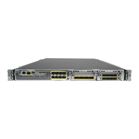
Cisco Firepower 4110 Manual
Hide thumbs
Also See for Firepower 4110:
- Hardware installation manual (84 pages) ,
- Preparative procedures & operational user manual (72 pages) ,
- Manual (42 pages)
Quick Links
Installation, Maintenance, and Upgrade
•
•
•
•
•
•
•
Install, Remove, and Replace the Network Module
Hot Swapping
Caution
Note
Remove and Replace the Fan Module, on page 4
Remove and Replace the SSD, on page 6
Remove and Replace the Power Supply Module, on page 9
Connect the DC Power Supply Module, on page 13
Install the FIPS Opacity Shield, on page 22
Starting with FXOS 2.3.1, the Firepower 10-Gb and 40-Gb network modules (without hardware bypass
support) support hot swapping, but you must hot swap with an identical network module, that is, a network
module with the same PID. See
network module offline using the appropriate CLI commands before removing the network module from
the chassis so that all network module configuration is saved. See the "Taking a Network Module Offline
or Online" topic in the Security Module/Engine Management chapter in the
Chassis Manager Configuration
We do not recommend that you remove the network module without bringing it properly offline using
the appropriate CLI commands.
You must have ROMMON 1.0.10 or later on the Supervisor to support hot swapping. For the ROMMON
upgrade procedure, see the "Firmware Upgrade" topic in the Image Management chapter in the
FXOS Firepower Chassis Manager Configuration Guide
To remove and replace the network modules that do not currently support hot swapping, power off the
chassis, replace the network module, and then power the chassis back on.
Acknowledgment is necessary if you decommission and physically remove a network module and do
not replace it, or if you replace it with another PID. See the "Acknowledging a Security Module/Engine"
Product ID Numbers
for the network module PIDs. You must bring the
Guide.
for your software version.
Installation, Maintenance, and Upgrade
Cisco FXOS Firepower
Cisco
1

Related Manuals for Cisco Firepower 4110


Summary of Contents for Cisco Firepower 4110
-
Page 1: Table Of Contents
CLI commands before removing the network module from the chassis so that all network module configuration is saved. See the “Taking a Network Module Offline or Online” topic in the Security Module/Engine Management chapter in the Cisco FXOS Firepower Chassis Manager Configuration Guide. - Page 2 Installation, Maintenance, and Upgrade Install, Remove, and Replace the Network Module topic in the Security Module/Engine Management chapter in the Cisco FXOS Firepower Chassis Manager Configuration Guide. Safety Warnings Take note of the following component replacement safety warnings: Warning Statement 1028 More Than One Power Supply This unit might have more than one power supply connection.
- Page 3 Installation, Maintenance, and Upgrade Install, Remove, and Replace the Network Module This procedure describes how to install a network module into an empty slot that has never contained a network module, and how to remove an installed network module and replace it with another network module. Step 1 To install a new network module for the first time into an empty slot, do the following: a) Power down the chassis by moving the power switch to the OFF position.
-
Page 4: Remove And Replace The Fan Module
Installation, Maintenance, and Upgrade Remove and Replace the Fan Module If the slot is to remain empty, install a blank faceplate to ensure proper airflow and to keep dust out of the chassis; otherwise, install another network module. Step 4 To replace a network module, hold the network module in front of the network module slot on the right of the chassis and pull the network module handle out. - Page 5 Installation, Maintenance, and Upgrade Remove and Replace the Fan Module Warning Statement 1028 More Than One Power Supply This unit might have more than one power supply connection. To reduce risk of electric shock, remove all connections to de-energize the unit. Warning Statement 1030 Equipment Installation Only trained and qualified personnel should be allowed to install, replace, or service this equipment.
-
Page 6: Remove And Replace The Ssd
Installation, Maintenance, and Upgrade Remove and Replace the SSD Figure 2: Remove the Fan Module Step 4 To replace a fan module, hold the fan module in front of the fan slot. Step 5 Push the fan module into the chassis until it is properly seated and the latches snap into place. If the system is powered on, listen for the fans. - Page 7 Installation, Maintenance, and Upgrade Remove and Replace the SSD the Advanced Malware Protection software feature. The MSP is supported beginning in FXOS 2.0.1. It is used as both storage and as the Malware application repository. RAID is not supported. Caution Do not switch the two SSDs.
- Page 8 Installation, Maintenance, and Upgrade Remove and Replace the SSD Warning Statement 1091 Installation by an Instructed Person Only an instructed person or skilled person should be allowed to install, replace, or service this equipment. See statement 1089 for the definition of an instructed or skilled person. Step 1 Save your configuration.
-
Page 9: Remove And Replace The Power Supply Module
Installation, Maintenance, and Upgrade Remove and Replace the Power Supply Module Remove and Replace the Power Supply Module You can remove and replace power supply modules while the system is running. Safety Warnings Take note of the following power and component removal safety warnings: Warning Statement 347 Failure to Secure the Expansion Module To reduce the risk of electric shock, secure the modules with the provided screws. - Page 10 Installation, Maintenance, and Upgrade Remove and Replace the Power Supply Module Warning Statement 1025 Use Copper Conductors Only To reduce risk of fire, use copper conductors only. Warning Statement 1028 More Than One Power Supply This unit might have more than one power supply connection. To reduce risk of electric shock, remove all connections to de-energize the unit.
- Page 11 Installation, Maintenance, and Upgrade Remove and Replace the Power Supply Module Warning Statement 1089 Instructed and Skilled Person Definitions An instructed person is someone who has been instructed and trained by a skilled person and takes the necessary precautions when working with equipment. A skilled person or qualified personnel is someone who has training or experience in the equipment technology and understands potential hazards when working with equipment.
- Page 12 Installation, Maintenance, and Upgrade Remove and Replace the Power Supply Module Figure 4: Remove the Power Supply Module If the slot is to remain empty, install a blank faceplate to ensure proper airflow and to keep dust out of the chassis; otherwise, install another power supply module.
-
Page 13: Connect The Dc Power Supply Module
Installation, Maintenance, and Upgrade Connect the DC Power Supply Module Connect the DC Power Supply Module This procedure describes how to install the DC power supply input power leads to the Firepower 4100 DC input power supply on the rear PDU of the chassis. Before You Begin •... - Page 14 Installation, Maintenance, and Upgrade Connect the DC Power Supply Module Safety Warnings Take note of the following power and component removal safety warnings: Warning Statement 347 Failure to Secure the Expansion Module To reduce the risk of electric shock, secure the modules with the provided screws. Warning Statement 1003 DC Power Disconnection Before performing any of the following procedures, ensure that power is removed from the DC circuit.
- Page 15 Installation, Maintenance, and Upgrade Connect the DC Power Supply Module Warning Statement 1028 More Than One Power Supply This unit might have more than one power supply connection. To reduce risk of electric shock, remove all connections to de-energize the unit. Warning Statement 1029 Blank Faceplates and Cover Panels Blank faceplates and cover panels serve three important functions: they reduce the risk of electric shock...
- Page 16 Installation, Maintenance, and Upgrade Connect the DC Power Supply Module Warning Statement 1090 Installation by Skilled Person Only a skilled person should be allowed to install, replace, or service this equipment. See statement 1089 for the definition of a skilled person. Warning Statement 1091 Installation by an Instructed Person Only an instructed person or skilled person should be allowed to install, replace, or service this equipment.
- Page 17 Installation, Maintenance, and Upgrade Connect the DC Power Supply Module Figure 7: Remove the M5 Screws Step 7 For easier cable management, insert the negative lead cable first. Replace the grounding lug with the cable in the following order—wire terminal, then the screw with the captive washer. Figure 8: Insert the Cables Step 8 Tighten the M5 screw with the captive washer to the recommended torque of 5 in-lbs for the positive stud and wire.
- Page 18 Installation, Maintenance, and Upgrade Connect the DC Power Supply Module Figure 9: Tighten the M5 Screws Step 9 Replace the terminal block plastic cover. The plastic cover is slotted and keyed to fit correctly over the terminal block. This cover should always be in place when power is applied to the terminals. Figure 10: Replace the Plastic Cover Installation, Maintenance, and Upgrade...
-
Page 19: Secure The Power Cord On The Ac Power Supply Module
Installation, Maintenance, and Upgrade Secure the Power Cord on the AC Power Supply Module Step 10 Set the DC disconnect switch in the circuit to ON. In a system with multiple power supplies, connect each power supply to a separate DC power source. In the event of a power source failure, if the second source is still available, it can maintain system operation. - Page 20 Installation, Maintenance, and Upgrade Secure the Power Cord on the AC Power Supply Module Warning Statement 1089 Instructed and Skilled Person Definitions An instructed person is someone who has been instructed and trained by a skilled person and takes the necessary precautions when working with equipment.
- Page 21 Installation, Maintenance, and Upgrade Secure the Power Cord on the AC Power Supply Module a) Locate the hexagonal ventilation hole on the power supply module at the center of the plug just below the power connector body (see the following figures). b) Plug the snapping portion of the tie wrap into the hexagonal hole.
-
Page 22: Install The Fips Opacity Shield
Because the FIPS opacity shield covers the serial number on the chassis, you need to copy the serial number on a label and attach it to the chassis where it can be retrieved or viewed easily before you install the FIPS opacity shield. You need the serial number when you call Cisco TAC. Before you begin... - Page 23 Installation, Maintenance, and Upgrade Install the FIPS Opacity Shield • #1 Phillips screwdriver • The following items from the FIPS kit: • One FIPS opacity shield • Four 8-32 x 0.375-inch screws used to attach the FIPS opacity shield to the cable management brackets •...
- Page 24 Step 5 Connect the cables to the ports. Install the cables according to your default software configuration as described in the Cisco Firepower 4100 Getting Started Guide. Make sure that the cables have enough slack to route them through the cable mounting brackets (as shown in Step 6 below).
- Page 25 Installation, Maintenance, and Upgrade Install the FIPS Opacity Shield Figure 17: Route the Cables Through the Cable Management Brackets Step 7 Attach the FIPS opacity shield to the cable management brackets using the four 8-32 x 0.375-inch Phillips screws provided in the FIPS kit. Installation, Maintenance, and Upgrade...
- Page 26 Do not remove the power cable until the power LED is off. After removing power from the chassis either by moving the power switch to OFF or unplugging the power cord, wait at least 10 seconds before turning power back ON. Step 12 See the Cisco Firepower 4100 Getting Started Guide for further configuration information. Installation, Maintenance, and Upgrade...