Table of Contents
Quick Links
Sec. 1
Service Information
Sec. 2
Disassembly Procedures
Sec. 3
Mechanism
Sec. 4
Electrical Adjustments
Sec. 5
Block Diagrams
Sec. 6
Schematic Diagrams
Sec. 7
Circuit Board Diagrams
Sec. 8
Exploded Views &
Replacement Parts List
Adjustment Procedures,Disassembly Procedures and Assembly Procedures for Mechanism Chassis are
separate volume from this service manual. (refer to the appendix in this CD-ROM.)
Please refer to the service manual for Z-Mechanism Chassis.(Order No. VSD9706M201, VRD9802005C2)
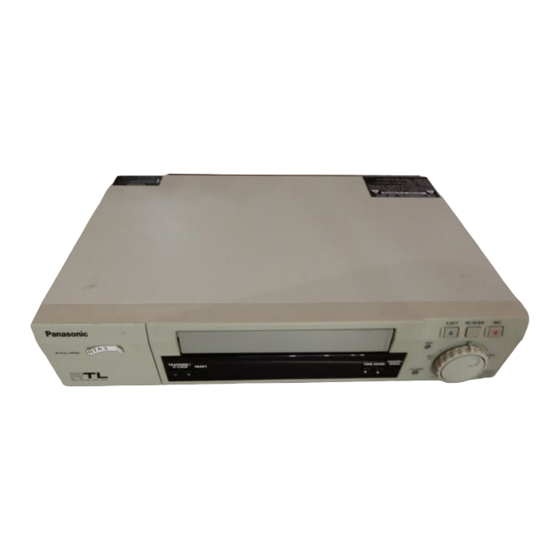
Time Lapse Recorder
AG-RT850P
Z-MECHANISM
© 2001 Matsushita Electric Industrial Co., Ltd. All rights reserved.
Unauthorized copying and distribution is a violation of law.
ORDER NO. BSD0109M622
S01
Chapters
Table of Contents

Related Manuals for Panasonic AG-RT850P


Summary of Contents for Panasonic AG-RT850P
- Page 1 ORDER NO. BSD0109M622 Sec. 1 Service Information Sec. 2 Disassembly Procedures Time Lapse Recorder Sec. 3 Mechanism AG-RT850P Sec. 4 Electrical Adjustments Sec. 5 Block Diagrams Z-MECHANISM Sec. 6 Schematic Diagrams Sec. 7 Circuit Board Diagrams Sec. 8 Exploded Views &...
- Page 2 WARNING This service information is designed for experienced repair technicians only and is not designed for use by the general public. It does not contain warnings or cautions to advise non-technical individuals of potential dangers in attempting to service a product. Products powered by electricity should be serviced or repaired only by experienced professional technicans.
- Page 3 SAFETY PRECAUTIONS GENERAL GUIDELINES ELECTROSTATICALLY SENSITIVE (ES) DEVICES 1. When servicing, observe the original lead dress. If a short Some semiconductor (solid state) devices can be damaged circuit is found, replace all parts which have been over- easily by static electricity. Such components commonly are heated or damaged by the short circuit.
- Page 4 Printed in Japan HCD0109NTKK66P...
- Page 5 SERVICE INFORMATION CONTENTS 1. SERVICE INFORMATION DISPLAY ..............INF-1 1-1. Purpose of Service Information Display................. INF-1 1-2. How to display Service Information ..................INF-1 1-3. Use of Service Modes ....................... INF-1 2. AUTO OFF AND ERROR MESSAGE..............INF-5 3. CHECKING OF MAIN C.B.A................... INF-6 4.
- Page 6 1. SERVICE INFORMATION DISPLAY 1-1. Purpose of Service Information Display This is information to aid trouble shooting by indicating the source of the malfunction. 1-2. How to display Service Information Press the FF and EJECT buttons simultaneously. In the service Information display, there are five digit numbers divided into 3 functions. The first digit indicates service mode that the unit is currently in.
- Page 7 (7) Mode 4: Service Data 1: The second recent fault indication code is displayed. Service Data 2: Indicate complementary data (VCR mode, mechanism position and so on) for the most recent fault indication code. (8) Mode 5: Service Data 1: The third recent fault indication code is displayed. Service Data 2: Indicate complementary data (VCR mode, mechanism position and so on) for the most recent fault indication code.
- Page 8 INF-3...
- Page 9 INF-4...
- Page 10 2. AUTO OFF AND ERROR MESSAGE ERROR CODE CONTENS CAUSE CONDITION If it is in POWER OFF mode, the mode turns to POWER ON and "d" blink indication. If a tape is inserted, the mode turns to half EJECT position and CONDENSATION cylinder rotates.
- Page 11 Rotate the Pole of Capstan motor to the 3. CHECKING OF clockwise the from the bottom in order to remove the tape slack. MAIN C.B.A. When Servicing the MAIN C.B.A, take out the MAIN C.B.A. and mechanism from the frame and turn over, and then connect Extension Cable (VFK2744) between the POWER C.B.A.
-
Page 12: Table Of Contents
DISASSEMBLY PROCEDURES CONTENTS Removal of The Top Cover ................DIS-1 Removal of The Front Panel ................DIS-1 Removal of The Power Supply C.B.A...............DIS-1 Removal of The Front R C.B.A................DIS-1 Removal of The Front L C.B.A................DIS-2 Removal of The YC SEP C.B.A................DIS-2 Removal of Mechanism Unit and Main C.B.A...........DIS-2 Removal of The Rear Jack C.B.A. -
Page 13: Removal Of The Top Cover
3. Removal of The Power Supply C.B.A. 1. Removal of The Top Cover 1. Remove the top Cover & the Front Panel. 1. Remove 4 screws (A) at left & right side. 2. Disconnect he Bridge connector (P6205) 2. Lift up rear portion and remove it. 3. -
Page 14: Removal Of The Front L C.b.a
5. Removal of The Front L C.B.A.. 7. Removal of Mechanism Unit and Main C.B.A.. 1. Remove the top cover & Front Panel. 2. Unlock 2 tabs (G) 1. Remove the top cover & Front Panel. 3. Disconnect a connector (P6701) from the Main 2. -
Page 15: Removal Of The Rear Jack C.b.a
5. Keep pressing 2 stoppers on the Cassette Holder 8. Removal of The Rear Jack C.B.A. Plate and press the Cassette Holder Plate to rear and remove 2 screws (N). 1. Loosen a screw (Q) and remove 2 screws (R), then remove the MIC &... - Page 16 MAINTENANCE AND MECHANISM CONTENTS MAINTENANCE 1. REGULAR MAINTENANCE......................MEC-1 2. CYLINDER UNIT REPLACEMENT ....................MEC-2 MECHANICAL ADJUSTMENT INFORMATION 1. TEST POINT ...........................MEC-4 2. SPECIFICATION ..........................MEC-4...
-
Page 17: Maintenance
Maintenance 1. REGULAR MAINTENANCE The purpose of periodic maintenance is to preserve the functioning of this machine throughout its useful life. The user or service dealer should perform these maintenance regularly to ensure that maximum utility is obtained from the machine. The VCR is a complicated place of equipment. - Page 18 Symbol Maintenace Requirement Remark Wipe dirt from the parts using soft cloth impregnated with Etyl-Alcohol. Ethyl-alcohol or Note: When cleaning rubber parts, avoid using excessive ● Cleaning Ceaning Liquid alcohol since it may accelerate deterioration of these (Purchase locally) parts. After cleaning with alcohol, wipe the alcohol quickly and thoroughly.
-
Page 19: Cylinder Unit Replacement
2. CYLINDER UNIT REPLACEMENT A. CYLINDER UNIT REPLACEMENT B. UPPER CYLINDER DISASSEMBLY Remove 3 screws (A) of the CYLINDER UNIT with a 1. Remove 2 screws (A). 2. Remove the Cylinder Stator Unit. magnetized screw diriver. 3. Remove 2 screws (B). 4. -
Page 20: Mechanical Adjustment Information
MECHANICAL ADJUSTMENT C. UPPER CYLINDER ASSEMBLY INFORMATION For reassembling, perform the steps in the reverse This section contains the supplementary information of order. Mechanical Adjustment Procedure for Z-Mechanisum. 1) Install the Cylinder Retainer so that the 2 holes Please refer to the Z-Mechanisumservice manual on top of the cylinder retainer are at right angles. - Page 21 ELECTRICAL ADJUSTMENT CONTENTS 1.PG Shifter Adjustment ........................EAD-1 2.Slow Free Run Adjustment .......................EAD-1...
- Page 22 1. PG Shifter Adjustment Turn OFF power. Connect the jumper wire between TP6902 and TP6901 on the Rear Jack C.B.A.. Turn ON power. Insert the Alignment Tape Confirm the unit is in STOP mode, then press the ¯ TRACKING and TIME MODE buttons simultaneously.
- Page 23 BLOCK DIAGRAMS CONTENTS OVERALL BLOCK DIAGRAM ..................BLK-1 VIDEO/AUDIO BLOCK (MAIN C.B.A.) DIAGRAM .............BLK-2 SYSTEM CONTROL/SERVO BLOCK (MAIN C.B.A.) DIAGRAM ......BLK-3 FRONT BLOCK (MAIN C.B.A.) DIAGRAM..............BLK-4...
-
Page 24: Overall Block Diagram
OVERALL BLOCK DIAGRAM BLK-1... -
Page 25: Video/Audio Block (Main C.b.a.) Diagram
VIDEO/AUDIO BLOCK (MAIN C.B.A.) DIAGRAM BLK-2... -
Page 26: System Control/Servo Block (Main C.b.a.) Diagram
SYSTEM CONTROL/SERVO BLOCK (MAIN C.B.A.) DIAGRAM BLK-3... -
Page 27: Front Block (Main C.b.a.) Diagram
FRONT BLOCK (MAIN C.B.A.) DIAGRAM BLK-4... - Page 28 SCHEMATIC DIAGRAMS About indication of a circuit name Circuit Name COMPONENT Circuit Board No. F1:SERVO (CTL) NAME DRAWING NO. CIRCUIT BOARD NO. KR2D53 (1/17) VEP82230A-1 Drawing No. SCM001 Page No. NOTE: NOTE: BE SURE TO MAKE YOUR ORDERS OF REPLACEMENT PARTS ACCORDING TO PARTS LIST. DO NOT USE THE PART NUMBER SHOWN ON THIS DRAWING FOR ORDERING.
- Page 29 CONTENTS MAIN FRONT (1/5) ............SCM1 SYSCON_SERVO (2/5)........SCM2 MOTOR_DRIVE (3/5) ........... SCM3 INTERFACE (4/5) ..........SCM4 VIDEO & AUDIO (5/5)........... SCM5 FRONT R FRONT_R (1/1)............. SCM6 FRONT L FRONT_L (1/1) ............. SCM7 REAR JACK REAR JACK (1/1) ..........SCM8 MIC JACK MIC JACK (1/1).............
-
Page 30: Front (1/5)
COMPONENT MAIN: FRONT 01/05 NAME DRAWING NO. CIRCUIT BOARD NO. KR6T44 (1/5) VEP06D90F SCM001... - Page 31 COMPONENT MAIN: SYSCON/SERVO 02/05 NAME DRAWING NO. CIRCUIT BOARD NO. KR6T44 (2/5) VEP06D90F SCM002...
- Page 32 COMPONENT MAIN: MOTOR_DRIVE 03/05 NAME DRAWING NO. CIRCUIT BOARD NO. KR6T44 (3/5) VEP06D90F SCM003...
-
Page 33: Interface (4/5)
COMPONENT MAIN: INTERFACE 04/05 NAME DRAWING NO. CIRCUIT BOARD NO. KR6T44 (4/5) VEP06D90F SCM004... - Page 34 COMPONENT MAIN (VIDEO&AUDIO) 05/05 NAME CIRCUIT BOARD NO. DRAWING NO. KR6U47 (5/5) VEP06D90F SCM005...
-
Page 35: Front R
COMPONENT FRONT_R 01/01 NAME DRAWING NO. CIRCUIT BOARD NO. KR6T27 (1/1) VEP06D91B SCM006... -
Page 36: Front L
COMPONENT FRONT_L 01/01 NAME DRAWING NO. CIRCUIT BOARD NO. KR6T28 (1/1) VEP06D92A SCM007... -
Page 37: Rear Jack
COMPONENT REAR_JACK 01/01 NAME DRAWING NO. CIRCUIT BOARD NO. KR4J69 (1/1) VEP04766C SCM008 COMPONENT MIC_JACK 01/01 NAME DRAWING NO. CIRCUIT BOARD NO. KR4K11 (1/1) VEP04774A SCM009... -
Page 38: Yc Sep
COMPONENT YC_SEP 01/01 NAME DRAWING NO. CIRCUIT BOARD NO. KR30011 (1/1) VEP03F67A SCM010... -
Page 39: Rs-232C (1/1)
COMPONENT RS-232C 01/01 NAME CIRCUIT BOARD NO. DRAWING NO. KR6T43 (1/1) VEP06D99A SCM011... -
Page 40: Power Supply
CAUTION MARK INDICATES THE PRIMARY CIRCUIT TO DISTINGUISH THE PRIMARY FROM THE SECONDARY IMPORTANT SAFETY NOTICE: CIRCUIT. COMPONENTS IDENTIFIED WITH THE MARK HAVE THE SPECIAL CHARACTERISTICS FOR SAFETY. PAY ATTENTION NOT TO RECEIVE AN ELECTRIC SHOCK DURING REPAIR AND SERVICE OF THE PRODUCTS. WHEN REPLACING ANY OF THESE COMPONENTS, USE ONLY THE SAME TYPE. -
Page 41: Interconnection
COMPONENT INTERCONNECTION 01/01 NAME CIRCUIT BOARD NO. DRAWING NO. KR9K11 (1/1) SCM013... - Page 42 CIRCUIT BOARD DIAGRAMS NOTE: NOTE: BE SURE TO MAKE YOUR ORDERS OF REPLACEMENT PARTS ACCORDING TO PARTS LIST. DO NOT USE THE PART NUMBER SHOWN ON THIS DRAWING FOR ORDERING. THE CORRECT PART NUMBER SHOWN IN THE PARTS LIST. AND MAY BE SLIGHTLY DIFERENT OR AMENDED SINCE THIS DRAWING WAS PREPARED. CAUTION MARK INDICATES THE PRIMARY CIRCUIT TO DISTINGUISH THE PRIMARY FROM THE SECONDARY CIRCUIT.
-
Page 43: Main C.b.a. (Vep06D90F)
MAIN C.B.A. (VEP06D90F) (FOIL SIDE) CBA-1... - Page 44 MAIN C.B.A. (VEP06D90F) (COMPONENT SIDE) CBA-2...
-
Page 45: Front R C.b.a. (Vep06D91B)
FRONT R C.B.A. (VEP06D91B) (FOIL SIDE) (COMPONENT SIDE) CBA-3... -
Page 46: Front L C.b.a. (Vep06D92A)
FRONT L C.B.A. (VEP06D92A) (FOIL SIDE) (COMPONENT SIDE) CBA-4... -
Page 47: Rear Jack C.b.a. (Vep04766C)
REAR JACK C.B.A. (VEP04766C) (FOIL SIDE) (COMPONENT SIDE) MIC JACK C.B.A. (VEP04774A) (FOIL SIDE) (COMPONENT SIDE) CBA-5... -
Page 48: Yc Sep C.b.a. (Vep03F67A)
YC SEP C.B.A. (VEP03F67A) (FOIL SIDE) (COMPONENT SIDE) RS-232C C.B.A. (VEP06D99A) (FOIL SIDE) (COMPONENT SIDE) CBA-6... -
Page 49: Power Supply C.b.a. (Vep01890B)
POWER SUPPLY C.B.A. (VEP01890B) (FOIL SIDE) (COMPONENT SIDE) CBA-7... - Page 50 EXPLODED VIEWS & REPLACEMENT PARTS LISTS Note: 1. *Be sure to make your orders of replacement parts according to this list. 2. Unless otherwise specified, all resistors are in OHMS, K=1,000 OHMS, all capacitors are in MICROFARADS (µF), P=µµF. 3. The P.C. Board untils marked with " " shown below the main assembled parts. 4.
- Page 51 Components identified with the mark have the special characteristics for safety. When replacing any of these components, use only the same type. MECHANICAL CHASSIS ASSEMBLY Ref.No. Part No. Part Name & Description Remarks Ref.No. Part No. Part Name & Description Remarks W1 (1) VMX2208...
- Page 52 Components identified with the mark have the special characteristics for safety. When replacing any of these components, use only the same type. MECHANICAL CHASSIS ASSEMBLY PRT-2...
- Page 53 Components identified with the mark have the special characteristics for safety. CHASSIS FRAME ASSEMBLY When replacing any of these components, use only the same type. Ref.No. Part No. Part Name & Description Remarks Ref.No. Part No. Part Name & Description Remarks 101(2) VGM1751...
- Page 54 Components identified with the mark have the special characteristics for safety. CHASSIS FRAME ASSEMBLY When replacing any of these components, use only the same type. B108 B106 B106 BACK UP REAR JACK C.B.A. E31 E32 C.B.A. B107 B106 RS-232C C.B.A. Y/C SEP C.B.A.
- Page 55 Components identified with the mark have the special characteristics for safety. PACKING PARTS ASSEMBLY When replacing any of these components, use only the same type. Components identified with the mark have the special characteristics for safety. PACKING PARTS ASSEMBLY When replacing any of these components, use only the same type. Ref.No.
- Page 56 Components identified with the mark have the special characteristics for safety. When replacing any of these components, use only the same type. ELECTRICAL REPLACEMENT PARTS LIST Ref.No. Part No. Part Name & Description Remarks Ref.No. Part No. Part Name & Description Remarks ■...
- Page 57 Ref.No. Part No. Part Name & Description Remarks Ref.No. Part No. Part Name & Description Remarks C3001 ECUM1H101JCN C.CAPACITOR CH 50V 100P ■ E3 VEP04766C REAR JACK C.B.A. 1 (RTL) C3002 ECEA0JKS101 E.CAPACITOR 6.3V 100U C3003 ECUM1H103KBN C.CAPACITOR CH 50V 0.01U C3004 ECUM1E104ZFN C.CAPACITOR CH 25V 0.1U...
- Page 58 Ref.No. Part No. Part Name & Description Remarks Ref.No. Part No. Part Name & Description Remarks C3105 ECEA1CKS220 E.CAPACITOR C6216 ECEA1CKS101 E.CAPACITOR 16V 100U C3111 ECUM1H470JCN C.CAPACITOR CH 50V C6217 ECA1AM221 E.CAPACITOR 10V 220U C4001 ECEA1CKS470 E.CAPACITOR C6218 ECUM1H103KBN C.CAPACITOR CH 50V 0.01U C4002 ECA1CM331 E.CAPACITOR...
- Page 59 Ref.No. Part No. Part Name & Description Remarks Ref.No. Part No. Part Name & Description Remarks IC6204 C0EBK0000012 Q4004,05 2SD1149-R TRANSISTOR IC6501 MN101C35DBD MICROCOMPUTER Q4007 2SB621-R TRANSISTOR IC6502 C3EBDG000016 Q4008 2SD592-R TRANSISTOR IC6503 C0EBE0000074 Q4009 2SB709A TRANSISTOR Q4010,11 2SD1149-R TRANSISTOR J3001 ERJ6GEY0R00 M.RESISTOR CH 1/10W...
- Page 60 Ref.No. Part No. Part Name & Description Remarks Ref.No. Part No. Part Name & Description Remarks R3033 ERJ6RBD102 M.RESISTOR CH 1/10W R4035 ERJ6GEYG272 M.RESISTOR CH 1/10W 2.7K R3034 ERJ6RBD621 M.RESISTOR CH 1/10W 620 R4036,37 ERJ6GEYG103 M.RESISTOR CH 1/10W 10K R3035 ERJ6RED560 M.RESISTOR CH 1/10W R4038...
- Page 61 Components identified with the mark have the special characteristics for safety. When replacing any of these components, use only the same type. Ref.No. Part No. Part Name & Description Remarks Ref.No. Part No. Part Name & Description Remarks R6213 ERJ6GEY0R00 M.RESISTOR CH 1/10W XSN3+8FN SCREW...
- Page 62 Ref.No. Part No. Part Name & Description Remarks Ref.No. Part No. Part Name & Description Remarks C3515 ECUM1H103ZFN C.CAPACITOR CH 50V 0.01U R3536 ERJ6RBD331 M.RESISTOR CH 1/10W 330 C3516 ECUM1H103KBN C.CAPACITOR CH 50V 0.01U R3537 ERJ6GEYG183 M.RESISTOR CH 1/10W 18K C3517 ECUM1C105ZFN C.CAPACITOR CH 16V...
- Page 63 1. SERVICE INFORMATION DISPLAY 1-1. Purpose of Service Information Display This is information to aid trouble shooting by indicating the source of the malfunction. 1-2. How to display Service Information Press the FF and EJECT buttons simultaneously. In the service Information display, there are five digit numbers divided into 3 functions. The first digit indicates service mode that the unit is currently in.
- Page 64 (7) Mode 4: Service Data 1: The second recent fault indication code is displayed. Service Data 2: Indicate complementary data (VCR mode, mechanism position and so on) for the most recent fault indication code. (8) Mode 5: Service Data 1: The third recent fault indication code is displayed. Service Data 2: Indicate complementary data (VCR mode, mechanism position and so on) for the most recent fault indication code.
- Page 65 INF-3...
- Page 66 INF-4...
- Page 67 2. AUTO OFF AND ERROR MESSAGE ERROR CODE CONTENS CAUSE CONDITION If it is in POWER OFF mode, the mode turns to POWER ON and "d" blink indication. If a tape is inserted, the mode turns to half EJECT position and CONDENSATION cylinder rotates.
- Page 68 Rotate the Pole of Capstan motor to the 3. CHECKING OF clockwise the from the bottom in order to remove the tape slack. MAIN C.B.A. When Servicing the MAIN C.B.A, take out the MAIN C.B.A. and mechanism from the frame and turn over, and then connect Extension Cable (VFK2744) between the POWER C.B.A.
- Page 69 3. Removal of The Power Supply C.B.A. 1. Removal of The Top Cover 1. Remove the top Cover & the Front Panel. 1. Remove 4 screws (A) at left & right side. 2. Disconnect he Bridge connector (P6205) 2. Lift up rear portion and remove it. 3.
- Page 70 5. Removal of The Front L C.B.A.. 7. Removal of Mechanism Unit and Main C.B.A.. 1. Remove the top cover & Front Panel. 2. Unlock 2 tabs (G) 1. Remove the top cover & Front Panel. 3. Disconnect a connector (P6701) from the Main 2.
- Page 71 5. Keep pressing 2 stoppers on the Cassette Holder 8. Removal of The Rear Jack C.B.A. Plate and press the Cassette Holder Plate to rear and remove 2 screws (N). 1. Loosen a screw (Q) and remove 2 screws (R), then remove the MIC &...
- Page 72 Maintenance 1. REGULAR MAINTENANCE The purpose of periodic maintenance is to preserve the functioning of this machine throughout its useful life. The user or service dealer should perform these maintenance regularly to ensure that maximum utility is obtained from the machine. The VCR is a complicated place of equipment.
- Page 73 Symbol Maintenace Requirement Remark Wipe dirt from the parts using soft cloth impregnated with Etyl-Alcohol. Ethyl-alcohol or Note: When cleaning rubber parts, avoid using excessive ● Cleaning Ceaning Liquid alcohol since it may accelerate deterioration of these (Purchase locally) parts. After cleaning with alcohol, wipe the alcohol quickly and thoroughly.
- Page 74 2. CYLINDER UNIT REPLACEMENT A. CYLINDER UNIT REPLACEMENT B. UPPER CYLINDER DISASSEMBLY Remove 3 screws (A) of the CYLINDER UNIT with a 1. Remove 2 screws (A). 2. Remove the Cylinder Stator Unit. magnetized screw diriver. 3. Remove 2 screws (B). 4.
- Page 75 MECHANICAL ADJUSTMENT C. UPPER CYLINDER ASSEMBLY INFORMATION For reassembling, perform the steps in the reverse This section contains the supplementary information of order. Mechanical Adjustment Procedure for Z-Mechanisum. 1) Install the Cylinder Retainer so that the 2 holes Please refer to the Z-Mechanisumservice manual on top of the cylinder retainer are at right angles.
- Page 76 1. PG Shifter Adjustment Turn OFF power. Connect the jumper wire between TP6902 and TP6901 on the Rear Jack C.B.A.. Turn ON power. Insert the Alignment Tape Confirm the unit is in STOP mode, then press the ¯ TRACKING and TIME MODE buttons simultaneously.
- Page 77 OVERALL BLOCK DIAGRAM BLK-1...
- Page 78 VIDEO/AUDIO BLOCK (MAIN C.B.A.) DIAGRAM BLK-2...
- Page 79 SYSTEM CONTROL/SERVO BLOCK (MAIN C.B.A.) DIAGRAM BLK-3...
- Page 80 FRONT BLOCK (MAIN C.B.A.) DIAGRAM BLK-4...
- Page 81 COMPONENT MAIN: FRONT 01/05 NAME DRAWING NO. CIRCUIT BOARD NO. KR6T44 (1/5) VEP06D90F SCM001...
- Page 82 COMPONENT MAIN: SYSCON/SERVO 02/05 NAME DRAWING NO. CIRCUIT BOARD NO. KR6T44 (2/5) VEP06D90F SCM002...
- Page 83 COMPONENT MAIN: MOTOR_DRIVE 03/05 NAME DRAWING NO. CIRCUIT BOARD NO. KR6T44 (3/5) VEP06D90F SCM003...
- Page 84 COMPONENT MAIN: INTERFACE 04/05 NAME DRAWING NO. CIRCUIT BOARD NO. KR6T44 (4/5) VEP06D90F SCM004...
- Page 85 COMPONENT MAIN (VIDEO&AUDIO) 05/05 NAME CIRCUIT BOARD NO. DRAWING NO. KR6U47 (5/5) VEP06D90F SCM005...
- Page 86 COMPONENT FRONT_R 01/01 NAME DRAWING NO. CIRCUIT BOARD NO. KR6T27 (1/1) VEP06D91B SCM006...
- Page 87 COMPONENT FRONT_L 01/01 NAME DRAWING NO. CIRCUIT BOARD NO. KR6T28 (1/1) VEP06D92A SCM007...
- Page 88 COMPONENT REAR_JACK 01/01 NAME DRAWING NO. CIRCUIT BOARD NO. KR4J69 (1/1) VEP04766C SCM008 COMPONENT MIC_JACK 01/01 NAME DRAWING NO. CIRCUIT BOARD NO. KR4K11 (1/1) VEP04774A SCM009...
- Page 89 COMPONENT YC_SEP 01/01 NAME DRAWING NO. CIRCUIT BOARD NO. KR30011 (1/1) VEP03F67A SCM010...
- Page 90 COMPONENT RS-232C 01/01 NAME CIRCUIT BOARD NO. DRAWING NO. KR6T43 (1/1) VEP06D99A SCM011...
- Page 91 CAUTION MARK INDICATES THE PRIMARY CIRCUIT TO DISTINGUISH THE PRIMARY FROM THE SECONDARY IMPORTANT SAFETY NOTICE: CIRCUIT. COMPONENTS IDENTIFIED WITH THE MARK HAVE THE SPECIAL CHARACTERISTICS FOR SAFETY. PAY ATTENTION NOT TO RECEIVE AN ELECTRIC SHOCK DURING REPAIR AND SERVICE OF THE PRODUCTS. WHEN REPLACING ANY OF THESE COMPONENTS, USE ONLY THE SAME TYPE.
- Page 92 COMPONENT INTERCONNECTION 01/01 NAME CIRCUIT BOARD NO. DRAWING NO. KR9K11 (1/1) SCM013...
- Page 93 MAIN C.B.A. (VEP06D90F) (FOIL SIDE) CBA-1...
- Page 94 MAIN C.B.A. (VEP06D90F) (COMPONENT SIDE) CBA-2...
- Page 95 FRONT R C.B.A. (VEP06D91B) (FOIL SIDE) (COMPONENT SIDE) CBA-3...
- Page 96 FRONT L C.B.A. (VEP06D92A) (FOIL SIDE) (COMPONENT SIDE) CBA-4...
- Page 97 REAR JACK C.B.A. (VEP04766C) (FOIL SIDE) (COMPONENT SIDE) MIC JACK C.B.A. (VEP04774A) (FOIL SIDE) (COMPONENT SIDE) CBA-5...
- Page 98 YC SEP C.B.A. (VEP03F67A) (FOIL SIDE) (COMPONENT SIDE) RS-232C C.B.A. (VEP06D99A) (FOIL SIDE) (COMPONENT SIDE) CBA-6...
- Page 99 POWER SUPPLY C.B.A. (VEP01890B) (FOIL SIDE) (COMPONENT SIDE) CBA-7...
- Page 100 Components identified with the mark have the special characteristics for safety. When replacing any of these components, use only the same type. MECHANICAL CHASSIS ASSEMBLY Ref.No. Part No. Part Name & Description Remarks Ref.No. Part No. Part Name & Description Remarks W1 (1) VMX2208...
- Page 101 Components identified with the mark have the special characteristics for safety. When replacing any of these components, use only the same type. MECHANICAL CHASSIS ASSEMBLY PRT-2...
- Page 102 Components identified with the mark have the special characteristics for safety. CHASSIS FRAME ASSEMBLY When replacing any of these components, use only the same type. Ref.No. Part No. Part Name & Description Remarks Ref.No. Part No. Part Name & Description Remarks 101(2) VGM1751...
- Page 103 Components identified with the mark have the special characteristics for safety. CHASSIS FRAME ASSEMBLY When replacing any of these components, use only the same type. B108 B106 B106 BACK UP REAR JACK C.B.A. E31 E32 C.B.A. B107 B106 RS-232C C.B.A. Y/C SEP C.B.A.
- Page 104 Components identified with the mark have the special characteristics for safety. PACKING PARTS ASSEMBLY When replacing any of these components, use only the same type. Components identified with the mark have the special characteristics for safety. PACKING PARTS ASSEMBLY When replacing any of these components, use only the same type. Ref.No.
- Page 105 Components identified with the mark have the special characteristics for safety. When replacing any of these components, use only the same type. ELECTRICAL REPLACEMENT PARTS LIST Ref.No. Part No. Part Name & Description Remarks Ref.No. Part No. Part Name & Description Remarks ■...
- Page 106 Ref.No. Part No. Part Name & Description Remarks Ref.No. Part No. Part Name & Description Remarks C3001 ECUM1H101JCN C.CAPACITOR CH 50V 100P ■ E3 VEP04766C REAR JACK C.B.A. 1 (RTL) C3002 ECEA0JKS101 E.CAPACITOR 6.3V 100U C3003 ECUM1H103KBN C.CAPACITOR CH 50V 0.01U C3004 ECUM1E104ZFN C.CAPACITOR CH 25V 0.1U...
- Page 107 Ref.No. Part No. Part Name & Description Remarks Ref.No. Part No. Part Name & Description Remarks C3105 ECEA1CKS220 E.CAPACITOR C6216 ECEA1CKS101 E.CAPACITOR 16V 100U C3111 ECUM1H470JCN C.CAPACITOR CH 50V C6217 ECA1AM221 E.CAPACITOR 10V 220U C4001 ECEA1CKS470 E.CAPACITOR C6218 ECUM1H103KBN C.CAPACITOR CH 50V 0.01U C4002 ECA1CM331 E.CAPACITOR...
- Page 108 Ref.No. Part No. Part Name & Description Remarks Ref.No. Part No. Part Name & Description Remarks IC6204 C0EBK0000012 Q4004,05 2SD1149-R TRANSISTOR IC6501 MN101C35DBD MICROCOMPUTER Q4007 2SB621-R TRANSISTOR IC6502 C3EBDG000016 Q4008 2SD592-R TRANSISTOR IC6503 C0EBE0000074 Q4009 2SB709A TRANSISTOR Q4010,11 2SD1149-R TRANSISTOR J3001 ERJ6GEY0R00 M.RESISTOR CH 1/10W...
- Page 109 Ref.No. Part No. Part Name & Description Remarks Ref.No. Part No. Part Name & Description Remarks R3033 ERJ6RBD102 M.RESISTOR CH 1/10W R4035 ERJ6GEYG272 M.RESISTOR CH 1/10W 2.7K R3034 ERJ6RBD621 M.RESISTOR CH 1/10W 620 R4036,37 ERJ6GEYG103 M.RESISTOR CH 1/10W 10K R3035 ERJ6RED560 M.RESISTOR CH 1/10W R4038...
- Page 110 Components identified with the mark have the special characteristics for safety. When replacing any of these components, use only the same type. Ref.No. Part No. Part Name & Description Remarks Ref.No. Part No. Part Name & Description Remarks R6213 ERJ6GEY0R00 M.RESISTOR CH 1/10W XSN3+8FN SCREW...
- Page 111 Ref.No. Part No. Part Name & Description Remarks Ref.No. Part No. Part Name & Description Remarks C3515 ECUM1H103ZFN C.CAPACITOR CH 50V 0.01U R3536 ERJ6RBD331 M.RESISTOR CH 1/10W 330 C3516 ECUM1H103KBN C.CAPACITOR CH 50V 0.01U R3537 ERJ6GEYG183 M.RESISTOR CH 1/10W 18K C3517 ECUM1C105ZFN C.CAPACITOR CH 16V...