
Related Manuals for Asus Aaeon AIOT-QM


Summary of Contents for Asus Aaeon AIOT-QM
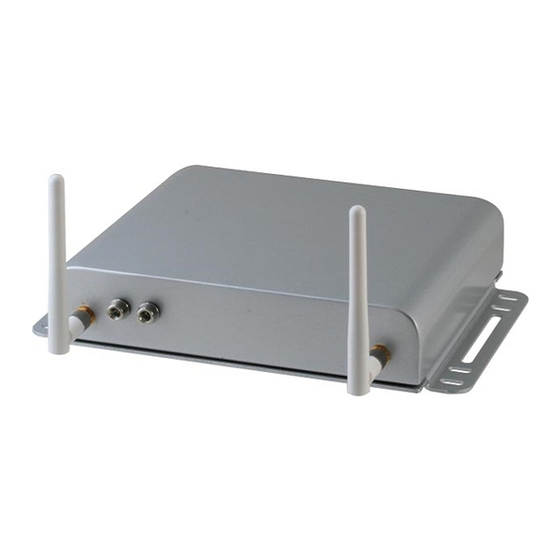
- Page 1 All manuals and user guides at all-guides.com AIOT-QM IoT Gateway System User’s Manual 1 Last Updated: December 16, 2015...
- Page 2 All manuals and user guides at all-guides.com Copyright Notice This document is copyrighted, 2015. All rights are reserved. The original manufacturer reserves the right to make improvements to the products described in this manual at any time without notice. No part of this manual may be reproduced, copied, translated, or transmitted in any form or by any means without the prior written permission of the original manufacturer.
- Page 3 All manuals and user guides at all-guides.com Acknowledgement All other products’ name or trademarks are properties of their respective owners. ® Microsoft Windows is a registered trademark of Microsoft Corp. ITE is a trademark of Integrated Technology Express, Inc. ...
- Page 4 All manuals and user guides at all-guides.com Packing List Before setting up your product, please make sure the following items have been shipped: Item Quantity AIOT-QM Product CD with User’s Manual (in pdf) If any of these items are missing or damaged, please contact your distributor or sales representative immediately.
- Page 5 All manuals and user guides at all-guides.com About this Document This User’s Manual contains all the essential information, such as detailed descriptions and explanations on the product’s hardware and software features (if any), its specifications, dimensions, jumper/connector settings/definitions, and driver installation instructions (if any), to facilitate users in setting up their product.
- Page 6 All manuals and user guides at all-guides.com Safety Precautions Please read the following safety instructions carefully. It is advised that you keep this manual for future references All cautions and warnings on the device should be noted. Make sure the power source matches the power rating of the device. Position the power cord so that people cannot step on it.
- Page 7 All manuals and user guides at all-guides.com If any of the following situations arises, please the contact our service personnel: Damaged power cord or plug Liquid intrusion to the device iii. Exposure to moisture Device is not working as expected or in a manner as described in this manual The device is dropped or damaged Any obvious signs of damage displayed on the device...
- Page 8 All manuals and user guides at all-guides.com FCC Statement This device complies with Part 15 FCC Rules. Operation is subject to the following two conditions: (1) this device may not cause harmful interference, and (2) this device must accept any interference received including interference that may cause undesired operation.
- Page 9 All manuals and user guides at all-guides.com China RoHS Requirements (CN) 产品中有毒有害物质或元素名称及含量 AAEON Boxer PC/ Industrial System 有毒有害物质或元素 部件名称 铅 汞 镉 六价铬 多溴联苯 多溴二苯醚 (Pb) (Hg) (Cd) (Cr(VI)) (PBB) (PBDE) 印刷电路板 × ○ ○ ○ ○ ○ 及其电子组件 外部信号 ×...
- Page 10 All manuals and user guides at all-guides.com China RoHS Requirement (EN) Poisonous or Hazardous Substances or Elements in Products AAEON Boxer PC/ Industrial System Poisonous or Hazardous Substances or Elements Hexavalent Polybrominated Polybrominated Component Lead Mercury Cadmium Chromium Biphenyls Diphenyl Ethers (Pb) (Hg) (Cd)
-
Page 11: Table Of Contents
All manuals and user guides at all-guides.com Table of Contents Chapter 1 - Product Specifications ..................1 Specifications ......................2 Chapter 2 – Hardware Information ..................4 Dimensions ....................... 5 Jumpers and Connectors (Board) ................ 8 List of Jumpers ......................9 2.3.1 Serial RS-232/422/485 Selector (JP1,2,3) ........ - Page 12 All manuals and user guides at all-guides.com 2.4.19 SD LED Header (CN36) ..............25 2.4.20 LED Assignments (LED1,2) ..............26 2.4.21 Front Panel Connector (J1) ............... 26 2.4.22 SPI JTAG Programming Port (J2) ............. 26 Preloaded Drivers ....................27 Preface...
-
Page 13: Chapter 1 - Product Specifications
All manuals and user guides at all-guides.com Chapter 1 Chapter 1 - Product Specifications... -
Page 14: Specifications
All manuals and user guides at all-guides.com Specifications System ® Intel Quark™ SoC X1021 Processor ® Intel Quark™ SoC X1021 Chipset Onboard 1 GB DDR3 800 MHz, ECC, System Memory un-buffered memory Display Interface Micro SD Slot x 1 Storage Device ... - Page 15 All manuals and user guides at all-guides.com VESA mounted 163 x 224.5 x 46 mm (6.42 x 8.83 x 1.81”) Dimension (W x H x D) Gross Weight 2.58 kg (6.28 lb) Net Weight 1.94 kg (4.28 lb) Environmental -20 ~ 70°C (-4 ~ 158°F) - with airflow Operating Temperature...
-
Page 16: Chapter 2 - Hardware Information
All manuals and user guides at all-guides.com Chapter 2 Chapter 2 – Hardware Information... -
Page 17: Dimensions
All manuals and user guides at all-guides.com Dimensions Device RESET DIGITAL DC-IN Chapter 2 – Hardware Information... - Page 18 All manuals and user guides at all-guides.com RESET DIGITAL DC-IN Chapter 2 – Hardware Information...
- Page 19 All manuals and user guides at all-guides.com Board Chapter 2 – Hardware Information...
-
Page 20: Jumpers And Connectors (Board)
All manuals and user guides at all-guides.com Jumpers and Connectors (Board) CN12 CN35 CN36 CN10 CN11 CN18 CN15 CN17 CN14 CN16 Chapter 2 – Hardware Information... -
Page 21: List Of Jumpers
All manuals and user guides at all-guides.com List of Jumpers Please refer to the table below for all of the board’s jumpers that you can configure for your application Label Function RS-232/422/485 Selector RS-232/422/485 Selector RS-232/422/485 Selector Chapter 2 – Hardware Information... -
Page 22: Serial Rs-232/422/485 Selector (Jp1,2,3)
All manuals and user guides at all-guides.com 2.3.1 Serial RS-232/422/485 Selector (JP1,2,3) RS-232 Function JP1 1-2 JP2 1-2 RS-232 (Default) JP3 1-2 RS-422 Function JP1 2-3 JP2 2-3 RS-422 JP3 1-2 Chapter 2 – Hardware Information... - Page 23 All manuals and user guides at all-guides.com RS-485 Function JP1 2-3 JP2 1-2 RS-485 JP3 2-3 Chapter 2 – Hardware Information...
-
Page 24: List Of Connectors
All manuals and user guides at all-guides.com List of Connectors Please refer to the table below for all of the board’s connectors that you can configure for your application Label Function JTAG Programming Port Box Header Battery Box Header ADC Box Header 10/100 RJ-45 Connector (LAN1) 10/100 RJ-45 Connector (LAN2) Mini USB Host Port Connector... -
Page 25: Jtag Programming Port Box Header (Cn1)
All manuals and user guides at all-guides.com 2.4.1 JTAG Programming Port Box Header (CN1) 3.3V TRST# Signal Signal +3.3V TRST# 2.4.2 Battery Box Header (CN2) Signal 2.4.3 ADC Box Header (CN3) AIN1 AIN0 AIN3 AIN2 AGND AGND AIN4 AIN5 AIN6 AIN7 Chapter 2 –... -
Page 26: 10/100 Rj-45 Connector (Lan1) (Cn4)
All manuals and user guides at all-guides.com ADC Mode Signal Signal AIN1 AIN0 AIN3 AIN2 Analog GND Analog GND AIN5 AIN4 AIN7 AIN6 2.4.4 10/100 RJ-45 Connector (LAN1) (CN4) LINK SPEED Pin 1 Pin 8 Signal Signal LAN1_MDI-TXP LAN1_MDI-TXN LAN1_MDI-RXP LAN1_TCT LAN1_MDI-RXN LAN1_RCT... -
Page 27: Mini Usb Host Port Connector (Cn6)
All manuals and user guides at all-guides.com Signal Signal LAN2_MDI-TXP LAN2_MDI-TXN LAN2_MDI-RXP LAN2_TCT LAN2_MDI-RXN LAN2_RCT LAN2_ACT-LED LAN2_ACT+LED LAN2_100-LED LAN2_100+LED 2.4.6 Mini USB Host Port Connector (CN6) Signal USBH0- USBH0+ 2.4.7 Hub Dual USB Connector (USB1,2) (CN7) Signal Signal USB1+ Chapter 2 – Hardware Information... -
Page 28: Hub Dual Usb (Usb3, 4) (Cn8)
All manuals and user guides at all-guides.com USB1- USB2+ USB2- 2.4.8 Hub Dual USB (USB3, 4) (CN8) Box Header USB4- USB4+ USB3+ USB3- Signal Signal +5 V USB4- USB4+ USB3+ USB3- +5 V M12 Connector Definition Signal Signal +5 V +5 V USB3+ USB3-... -
Page 29: Digital I/O (Cn9)
All manuals and user guides at all-guides.com USB4- Mating Connector Definition USB 1 Signal Signal +5 V USB4- USB4+ USB 2 Signal Signal +5 V USB3- USB3+ 2.4.9 Digital I/O (CN9) Box Header GPIO10 GPIO20 GPIO11 GPIO21 GPIO12 GPIO22 GPIO14 GPIO23 GPIO24 GPIO15... - Page 30 All manuals and user guides at all-guides.com Signal Signal GPIO10 GPIO20 GPIO11 GPIO21 GPIO12 GPIO22 GPIO14 GPIO23 GPIO15 GPIO24 GPIO16 GPIO25 GPIO17 GPIO26 GPIO30 GPIO27 +3.3V DIO GND +3.3V M12 Connector Definition Signal Signal DIO_GPIO10 DIO_GPIO20 DIO_GPIO11 DIO_GPIO21 DIO_GPIO12 DIO_GPIO22 DIO_GPIO14 DIO_GPIO23 DIO GND...
-
Page 31: Zigbee / Energy Spi Module Box Header (Cn10)
All manuals and user guides at all-guides.com Mating Connector Definition Signal Signal DIO_GPIO10 DIO_GPIO20 DIO_GPIO11 DIO_GPIO21 DIO_GPIO12 DIO_GPIO22 DIO_GPIO14 DIO_GPIO23 DIO GND +3.3 V +3.3 V 2.4.10 ZigBee / Energy SPI Module Box Header (CN10) Analog GND GPIO5-SPARE GPIO6-SPI1-ID3 GPIO7-SPI1-ID2 GPIO2-SPI1-CS0-N GPIOSUS0-SPI1-ID1 SPI1-SCK... -
Page 32: I2C Box Header (Cn11)
All manuals and user guides at all-guides.com GPIO6-SPI1-ID3 GPIO7-SPI1-ID2 GPIO2-SPI1-CS0-N GPIOSUS-SPI1-ID1 SPI1-SCK GPIOSUS1-SPI1-ID0 SPI1-MOSI GPIOS2-SPI1-RST-N SPI1-MISO-R GPIO3-SPI1-CS1-N +3.3V +3.3V 2.4.11 I2C Box Header (CN11) I2C-SDA I2C-SCK +3.3V Signal +3.3V I2C-SCK I2C-SDA 2.4.12 Micro SD Card Connector (CN12) Signal Signal SD-DAT2 SD-DAT3 SD-CMD +3.3V... -
Page 33: Serial Port Rs-232/422/485 Connector (Com1) (Cn14)
All manuals and user guides at all-guides.com 2.4.13 Serial Port RS-232/422/485 Connector (COM1) (CN14) RS-232 Signal Signal DCDAX SINAX SOUTAX DTRAX DSRAX RTSAX CTSAX RIAX RS-422 Signal Signal RS-422_TX- RS-422_RX+ RS-422_TX+ RS-422_RX- RS-485 Signal Signal RS485_D- RS485_D+ Chapter 2 – Hardware Information... -
Page 34: Serial Port (Com2) (Cn15)
All manuals and user guides at all-guides.com 2.4.14 Serial Port (COM2) (CN15) Box Header DCDBX RXBX RTSBX TXBX CTSBX DTRB Signal Signal DCDBX RXBX RTSBX TXBX CTSBX DTRB M12 Connector Definition Signal Signal DCDBX TXBX RTSBX CTSBX RXBX DTRB Chapter 2 – Hardware Information... -
Page 35: Dc 5V Or 9V~24V Input Connector (Cn16)
All manuals and user guides at all-guides.com Mating Connector Definition Signal Signal DCDBX RXBX TXBX DTRB RTSBX CTSBX 2.4.15 DC 5V or 9V~24V Input Connector (CN16) Signal 5V or 9V~24V Chapter 2 – Hardware Information... -
Page 36: Dc 5V Or 9V~24V Input (Cn17)
All manuals and user guides at all-guides.com 2.4.16 DC 5V or 9V~24V Input (CN17) Box Header 5V or 9V~24V Signal 5V or 9V~24V M12 Connector Definition Signal 5V or 9V~24V Mating Connector Definition Signal 9V~24V Chapter 2 – Hardware Information... -
Page 37: Power Led Box Header (Cn18)
All manuals and user guides at all-guides.com 2.4.17 Power LED Box Header (CN18) Signal 5V LED 2.4.18 Micro SIM Socket (CN35) Signal Signal UIM_PWR UIM_RST UIM_CLK UIM_VAPP UIM_DATA 2.4.19 SD LED Header (CN36) Signal Chapter 2 – Hardware Information... -
Page 38: Led Assignments (Led1,2)
All manuals and user guides at all-guides.com SD-LED 2.4.20 LED Assignments (LED1,2) Signal LED1 Micro-SD LED LED2 VCC Power OK LED 2.4.21 Front Panel Connector (J1) Signal RESET-N 2.4.22 SPI JTAG Programming Port (J2) Signal Signal +3.3V LSPI-SS-N LSPI-SCK LSPI-MISO-R LSPI-MOSI LSPI-HOLD# Chapter 2 –... -
Page 39: Preloaded Drivers
All manuals and user guides at all-guides.com Preloaded Drivers Drivers for the modules listed below are preloaded with the AIOT-QM and hence no additional installations are required. However, users still have to acquire the appropriate drivers from their respective manufacturers if modules not listed below are to be used. Wifi ...