Table of Contents
Quick Links
Table of Contents

Related Manuals for Honeywell AC-250NXS


Summary of Contents for Honeywell AC-250NXS
- Page 1 AC-250NXS User Manual Rev. 1 | Dec 08 2020...
-
Page 2: Table Of Contents
Safety and Compliance Information ....................5 Autonomous Valve shutoff configuration ..................7 Alert Notification configuration ....................... 7 Integrated CAT-M1 communications module................. 7 AC-250NXS Gas Meter specifications ................... 8 Install the AC-250NXS Gas Meter ....................8 AC-250NXS Gas Meter LCD Operation ..................10 Security ............................22... -
Page 3: Product Overview
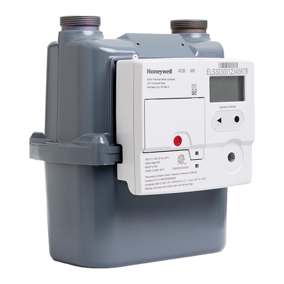
Being one of the smallest and lightest diaphragm gas meters in the US market, AC-250NXS is reliable, accurate, easy to install and fits in tighter spaces, such as meter trees in apartment complexes. -
Page 4: Product Components
• Configurable valve autonomous shut-off thresholds during High gas Pressure or Temperature Product Components The AC-250NXS Gas Meter features these components in a compact meter. • AC-250NXS Gas Meter index - The index contains the Cat-M1 communications module, one or two batteries, one replaceable and the liquid crystal display (LCD). -
Page 5: Safety And Compliance Information
The meter must not be co-located or operated in conjunction with any other antenna or transmitter. Liability Elster American Meter Company and its parent Honeywell will not be liable for damage resulting from non-observance of the instructions and non-compliant use. - Page 6 • Consult the dealer or an experienced radio/TV technician for help If you experience trouble with this equipment, please contact Customer Services at Honeywell Elster American Meter. Do not attempt to repair this equipment yourself unless you are replacing the entire module.
-
Page 7: Autonomous Valve Shutoff Configuration
Head End System. Alert Notification configuration The AC-250NXS has multiple alert notifications reported to Head End System. The following are some of the critical alert notifications: •... -
Page 8: Ac-250Nxs Gas Meter Specifications
Standards Designed in compliance with ANSI B109.1, ANSIB109.0 Regulatory This device complies with Part 15 of the FCC rules. FCC ID: XMR2020BG95M2 Component materials Single coat polyester Install the AC-250NXS Gas Meter © Elster American Meter Company LLC – 2020... - Page 9 This section describes how to install AC-250NXS Gas Meter. To install a gas meter, perform below steps: 3. The gas meter should be installed as close to level as possible in order to ensure accurate operation. 4. Avoid installing the meter in locations where the meter casing is in direct contact with soil or concrete walls.
-
Page 10: Ac-250Nxs Gas Meter Lcd Operation
1 – Menu area 2 – Information area 3 – Status line (symbols) • symbols are only displayed when a valve is integrated in the gas meter. AC-250NXS is equipped with an integrated valve. User keys, Selection Key and Symbols •... - Page 11 Icon Description Pairing is successful with cellular communication or Optical communication. Valve/gas flow closed. Valve/gas flow released. Invalid data Fault message Low battery. This symbol is only displayed when battery power is low. Marking for metrology-relevant data. Multiple sensor data invalid. Gas Temperature is above the configured maximum allowed gas temperature measurement beyond which a range error alert is reported Gas Pressure is above the configured maximum allowed gas pressure measurement.
- Page 12 Navigating within the menu • The menu is constructed hierarchically. • Depending on the configuration, some menu options may be missing. • The “Current meter reading” main screen appears when switching on the index or when a button is pressed when display is off. •...
- Page 13 Cat-M1 screen. The Cat-M1 screen has 4 sub- screens, navigate to sub-screens using select button. The AC-250NXS supports Cat-M1 cellular communication. The first screen shows the cellular connection status. A manual remote call can be invoked by holding the select button for 5- seconds.
- Page 14 On Cat-M1 screen, press the left button to navigate to Local Com screen. The AC-250NXS supports optical communication for local installation and maintenance activities. The optical port can be enabled by pressing the select button, the meter immediately opens the port and ready for association. This indication can be seen by an antenna symbol bottom middle of the screen.
- Page 15 Using Select key, a user can navigate to application event screen and navigate to individual events using navigation key. Each individual event includes Event ID (which is pre-defined number for each type of event), time it occurred and the related information of the event.
- Page 16 The temperature screen indicates the current gas temperature (tg), Max and Min gas temperature measurement range, base temperature and specific temperature used for temperature compensation which are modifiable by the end user. © Elster American Meter Company LLC – 2020...
- Page 17 The AC-250NXS meter includes two batteries: • Primary battery and • Replacement battery along with an HLC (Hybrid Layer Capacitor) which stores the energy by charging from the battery to supply enough current during cellular communication. The battery related sub-screen display below parameters of both these batteries: •...
- Page 18 AC520NXS has integrated Valve, which can be operated locally from the optical port from FieldSense tool or remotely over cellular CAT-M1 network from Connexo or NetSense. The Valve also operates autonomously by meter when a high pressure or high temperature is detected by the meter based on configuration.
- Page 19 Command Scenario Open Valve Close Valve Open Valve Close Valve Time out or select button Time out or select button © Elster American Meter Company LLC – 2020...
- Page 20 The meter displays Valve is in Open State if valve is already in ON state and Open command is issued. Valve Close Operation: When Valve close command is issued in open state, the Valve moves into closing position and valve close successfully message is displayed on the screen. An error message will be displayed in a scenario when there are issues in closing the Valve instead of success message.
- Page 21 Flow Test: The Flow test start screen is a part of Service screen menu. After pressing the select button on this screen, the flow test starts for a duration of 120 seconds. and the screen changes to Flow Test Running screen. Time elapsed Number of pulses Time remaining for completion of test...
-
Page 22: Security
Honeywell can read non-personal data from a returned meter for quality control and diagnostics through a physical connection and via display menu. The data will not be forwarded to a third party. Honeywell cannot access the data by means of a remote interface. - Page 23 Honeywell investigates all reports of security vulnerabilities affecting Honeywell products and services. For details on Honeywell security policy, visit https://www.honeywell.com/en-us/product-security. To report a potential security vulnerability against any Honeywell product, please follow the instructions https://www.honeywell.com/en-us/product-security under the Vulnerability Reporting section.