Yamaha EF3000iSE Service Manual
Hide thumbs
Also See for EF3000iSE:
- Installation manual ,
- Service manual (327 pages) ,
- Owner's manual (148 pages)
Table of Contents
Quick Links
Table of Contents
Troubleshooting

Related Manuals for Yamaha EF3000iSE


Summary of Contents for Yamaha EF3000iSE
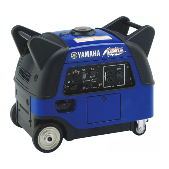
- Page 1 SERVICE MANUAL EF3000iSE 7WL-28197-E0 310140...
- Page 2 FOREWORD HOW TO USE THIS MANUAL This manual was written by the Yamaha Motor PARTICULARLY IMPORTANT Company primarily for use by Yamaha dealers INFORMATION and their qualified mechanics. It is not possible This material is distinguished by the following to put an entire mechanic’s education into one notation.
- Page 3 D Apply gear oil E Apply molybdenum disulfide oil F Apply wheel bearing grease G Apply lightweight lithium-soap base grease H Apply molybdenum disulfide grease I Apply a locking agent (LOCTITE ® J Apply Yamaha bond K Use a new one...
- Page 4 INDEX GENERAL INFORMATION PERIODIC INSPECTIONS AND ADJUSTMENTS ENGINE ELECTRICAL SPECIFICATIONS...
-
Page 5: Table Of Contents
CHAPTER 1. ELECTRICAL ......... 2-18 SPARK PLUG ........2-18 GENERAL INFORMATION MAIN SWITCH ........2-19 ECONOMY SWITCH ......2-20 MACHINE IDENTIFICATION ....1-1 PILOT LIGHT ........2-20 SERIAL NUMBER ....... 1-1 OVERLOAD WARNING LIGHT ..2-20 STARTING SERIAL NUMBER .... 1-1 DC CIRCUIT BREAKER .... - Page 6 GENERATOR ......... 3-21 CARBURETOR ........3-45 GENERATOR ASSEMBLY FLOAT HEIGHT INSPECTION ..3-49 REMOVAL ......... 3-22 CHOKE CABLE INSTALLATION ..3-50 GENERATOR ASSEMBLY THROTTLE CONTROL MOTOR ..3-50 INSTALLATION ......... 3-23 TROUBLESHOOTING ......3-51 CYLINDER HEAD COVER THROTTLE CONTROL SYSTEM ..3-56 AND CYLINDER HEAD ......
-
Page 7: Chapter 1. General Information
MACHINE IDENTIFICATION INFO GENERAL INFORMATION MACHINE IDENTIFICATION SERIAL NUMBER The serial number is printed on a label 1 which is affixed to the generator as shown. NOTE: The first three characters of this number are for model identification, the remaining digits SWL1010T are the unit production number. -
Page 8: Important Information
Be sure to use the correct special tool for the job to guard against damage. SVU1040 2. Oil, grease and seals Be sure to use genuine Yamaha oils, grease and sealers, or the equivalents. SVU1050 3. Expendable parts Always replace the gaskets, O-rings, cotter pins and circlips with new parts when servicing engine. -
Page 9: All Replacement Parts
IMPORTANT INFORMATION INFO ALL REPLACEMENT PARTS We recommend the use of genuine Yamaha parts for all replace- ments. Use oil and/or grease, recommended by Yamaha, for assembly and adjustment. GASKETS, OIL SEALS, AND O-RINGS 1. All gaskets, seals, and O-rings should be replaced when an engine is overhauled. -
Page 10: Special Tools And Testers
SPECIAL TOOLS AND TESTERS INFO SPECIAL TOOLS AND TESTERS The proper special tools are necessary for complete and accurate tune-up and assembly. Using the correct special tool will help pre- vent damage caused by the use of improper tools or improvised techniques. - Page 11 SPECIAL TOOLS AND TESTERS INFO 5. Inductive self-powered tachometer 1 P/N. YU-8036-B Engine tachometer 2 P/N. 90890-03113 3 P/N. 90793-80009 4 P/N. 90793-80032 SWL1010 This instrument is used for reading engine r/min. SWL1020 SWL1040 SWL1050 6. Compression gauge 1 P/N. YU-33223, 90890-03081 Adapter 2 P/N.
- Page 12 SPECIAL TOOLS AND TESTERS INFO 10.Rotor assembly holder Commercially available This tool is necessary for holding the rotor. SWL1030 11.Rotor puller 1 P/N. YU-33270-B 2 P/N. 90890-01362 This tool is necessary for removing the flywheel. SVU1210 SVU1220 12.Pocket tester P/N. YU-03112-C, 90890-03112 This instrument is necessary for checking the electrical system.
-
Page 13: Periodic Inspections And Adjustments
INSP INTRODUCTION/MAINTENANCE INTERVALS CHART (For Canada)/ PERIODIC MAINTENANCE/LUBRICATION INTERVALS PERIODIC INSPECTIONS AND ADJUSTMENTS INTRODUCTION This chapter includes all information necessary to perform recommended inspections and adjust- ments. These preventive maintenance procedures, if followed, will ensure more reliable machine operation and a longer service life. The need for costly overhaul work will be greatly reduced. This information applies to machines already in service as well as new machines that are being prepared for sale. -
Page 14: Covers, Panels, And Caps
7.0 Nm (0.7 m · kg, 5.1 ft · lb) NOTE: • The EF3000iSE are equipped with soundproof covers and panels that cover the engine and frame. • To make periodic maintenance checks easy, remove the applicable cover or panel. -
Page 15: Engine
ENGINE OIL LEAKAGE CHECKING/ INSP OIL LEVEL CHECKING ENGINE ENGINE OIL LEAKAGE CHECKING 1. Remove: • Panel 2 • Panel 4 Refer to “COVERS, PANELS, AND CAPS”. 2. Check the areas outside of the engine for oil leakage. SWL2020J Oil leakage → Replace the gasket, oil seal, or O-ring. -
Page 16: Oil Replacement
OIL LEVEL CHECKING/ INSP OIL REPLACEMENT 4. Install: • Oil filler cap • Panel 2 Refer to “COVERS, PANELS, AND CAPS”. NOTE: Tighten the oil filler cap securely by hand. OIL REPLACEMENT 1. Warm up the engine for several minutes. 2. -
Page 17: Fuel Leakage
OIL REPLACEMENT/ INSP FUEL LEAKAGE É Recommended oil: È SAE #30 or 10W-30 or 10W-40 É SAE #20 or 10W-30 or 10W-40 Ê SAE 10W or 10W-30 or 10W-40 SAE #40: Above 35 °C (95 °F) Engine oil quantity: 0.6 L (0.53 Imp qt, 0.63 US qt) SVW2070T NOTE: Recommended engine oil classification:... -
Page 18: Fuel Tank Filter
FUEL LEAKAGE/ INSP FUEL TANK FILTER 4. Check: • Leakage Check at fuel tank, fuel cock, fuel hoses, and carburetor. CAUTION: Replace the fuel hoses every four years. 5. Install: • Fuel tank SWL2070J Refer to “FUEL TANK AND CONTROL BOX”... -
Page 19: Fuel Pipe Strainer
INSP FUEL PIPE STRAINER FUEL PIPE STRAINER WARNING Do not smoke, and keep away from open flames, sparks, or any other source of fire when handling or in the vicinity of fuel. 1. Drain the fuel. 2. Remove: • Cover 1 •... -
Page 20: Air Filter Element
INSP AIR FILTER ELEMENT AIR FILTER ELEMENT 1. Remove: • Panel 4 • Cover 5 Refer to “COVERS, PANELS, AND CAPS”. 2. Remove: • Hooks 1 • Air filter element case 2 SWL2090J 3. Remove: • Air filter element 1 1 •... -
Page 21: Muffler
AIR FILTER ELEMENT/ INSP MUFFLER 8. Install: SWL2120J • Air filter element case 1 • Hooks 2 NOTE: • Align the projection a of the air filter case 1 with the slot b in the air filter element bracket, and then install the air filter case. •... -
Page 22: Valve Clearance Adjustment
MUFFLER/ INSP VALVE CLEARANCE ADJUSTMENT 4. Decarbonize: • Exhaust pipe 1 • Muffler 2 • Muffler screen 3 • Spark arrester 4 Tap on the muffler in the area shown in the illustration to loosen carbon buildup, and then shake it out of the end of the muffler. - Page 23 INSP VALVE CLEARANCE ADJUSTMENT 3. Gently pull the recoil starter to bring the piston to top dead center of its compres- sion stroke (when screwdriver inserted into the spark plug hole reaches the highest position). NOTE: If the piston is at top dead center of the exhaust stroke, turn the crankshaft one full turn (360°) to set the piston at top dead center SWL2140J...
- Page 24 INSP VALVE CLEARANCE ADJUSTMENT 5. Adjust: • Valve clearance Adjustment steps: • Loosen the locknut 1. • Turn the adjuster 2 in or out to obtain the proper clearance. Adjuster Valve clearance SWL2160J Turn in Decrease Turn out Increase • Tighten the locknut 1. Locknut: 10 Nm (1.0 m ·...
-
Page 25: Air Gap Between Tci Unit And Flywheel Magneto
AIR GAP BETWEEN TCI UNIT AND FLYWHEEL INSP MAGNETO AIR GAP BETWEEN TCI UNIT AND FLY- WHEEL MAGNETO 1. Remove: • Fuel tank Refer to “FUEL TANK AND CONTROL BOX” in CHAPTER 3. • Air filter element assembly Refer to “AIR FILTER ASSEMBLY AND CONTROL UNIT”... - Page 26 AIR GAP BETWEEN TCI UNIT AND FLYWHEEL INSP MAGNETO/COMPRESSION PRESSURE 4. Install: • Flywheel magneto cover • Recoil starter Refer to “RECOIL STARTER AND FLY- WHEEL MAGNETO” in CHAPTER 3. • Carburetor Refer to “CARBURETOR” in CHAPTER • Air filter element assembly Refer to “AIR FILTER ASSEMBLY AND CONTROL UNIT”...
-
Page 27: Compression Pressure
INSP COMPRESSION PRESSURE 5. Measure: • Compression To measure the compression, set the main switch to “START” “ ” or set it to “ON” “ ” and pull the recoil starter until the needle stops rising on the com- pression gauge. Standard compression pressure: 400 ~ 600 kPa (4 ~ 6 kg/cm... -
Page 28: Engine Speed (No Load)
ENGINE SPEED (NO LOAD)/ INSP ECONOMY ENGINE SPEED ENGINE SPEED (NO LOAD) 1. Remove: • Panel 4 Refer to “COVERS, PANELS, AND CAPS”. 2. Connect: • Inductive self-powered tachometer or engine tachometer 1 SWL2200J Inductive self-powered tachome- ter: YU-8036-B Engine tachometer: 90890-03113 (90793-80009, 90793-80032) 3. -
Page 29: Choke Cable
ECONOMY ENGINE SPEED/ INSP CHOKE CABLE/BREATHER HOSE 3. Inspect: È É • Economy engine speed Specified engine speed → OK Out of specification → Refer to “TROU- BLE SHOOTING” in CHAPTER 3. Inspection steps: • Turn the economy switch 1 to “ON” ”... -
Page 30: Electrical
INSP SPARK PLUG ELECTRICAL SPARK PLUG WARNING Inspect and adjust the areas around the cylinder head after the engine has cooled down completely. CAUTION: Before removing the spark plug, use com- pressed air to clean the cylinder head cover to prevent dirt from falling into the engine. -
Page 31: Main Switch
SPARK PLUG/ INSP MAIN SWITCH 5. Tighten: • Spark plug Spark plug: 18 Nm (1.8 m · kg, 13 ft · lb) NOTE: To prevent thread damage, finger tighten a the spark plug before tightening it to the speci- fied torque b. SVU2280 6. -
Page 32: Economy Switch
ECONOMY SWITCH/PILOT LIGHT/ INSP OVERLOAD WARNING LIGHT ECONOMY SWITCH È É 1. Check: • Economy switch 1 È 120 V-60 Hz, 220 V-50 Hz É 230 V-50 Hz Checking steps: • Set the economy switch 1 to “ON” ” a. “... -
Page 33: Dc Circuit Breaker
DC CIRCUIT BREAKER/ INSP DC CIRCUIT BREAKER (120 V-60 Hz) DC CIRCUIT BREAKER 1. Check: • DC circuit breaker Checking steps: • Check if the DC circuit breaker knob 1 is ” a. set to “RESET” “ • If the knob 1 is set to “OFF” “ ”... -
Page 34: Receptacle
RECEPTACLE/ INSP AC SWITCH (NFB) (120 V-60 Hz/23.5 A) RECEPTACLE È 1. Check: • DC receptacle (12 V, 8.3 A) 1 • DC receptacle (12 V, 12 A) 2 • AC receptacles (15 A) 3 • AC receptacle (23.3 A) 4 •... -
Page 35: Ac Switch (Nfb) (120 V-60 Hz/15 A)
AC SWITCH (NFB) (120 V-60 Hz/15 A)/ INSP FUSES AC SWITCH (NFB) (120 V-60 Hz/15 A) 1. Set the AC switch (NFB) 1 to the “ON” a AC SW position. 2. Connect the pocket tester (AC 120 V) to the AC receptacle (15 A) and check the AC switch (NFB) for continuity. - Page 36 INSP FUSES 4. Check: • Fuses Checking steps: • Connect the pocket tester (Ω × 1) to a fuse and check the continuity. NOTE: Set the pocket tester selector to “Ω × 1” Pocket tester: YU-03112-C, 90890-03112 • If the pocket tester indicates “∞”, replace the fuse.
-
Page 37: Battery
BATTERY/ INSP BATTERY TERMINAL BATTERY WARNING Battery fluid is poisonous and dangerous, causes severe burns, etc. Contains sulfuric acid. Avoid contact with skin, eyes or clothing. Antidote: EXTERNAL – Flush with water. INTERNAL – Drink large quantities of water or milk. Follow with milk of magnesia, DANGER/POISON beaten egg or vegetable oil. -
Page 38: Battery Electrolyte
BATTERY TERMINAL/ INSP BATTERY ELECTROLYTE 4. Install: • Battery • Battery band • Battery bracket CAUTION: Connect the positive lead to the battery ter- minal first. 5. Install: • Cover 5 Refer to “COVERS, PANELS, AND CAPS”. BATTERY ELECTROLYTE 1. Fill: CAUTION: •... - Page 39 INSP BATTERY ELECTROLYTE a. Place the battery on a level surface. b. Remove the sealing sheet 1. 2 Filler port SWL2320J c. Take the electrolyte container out of the vinyl bag. d. Detach the strip of caps (used as battery plugs) 1.
- Page 40 INSP BATTERY ELECTROLYTE g. Leave the container in this position for 20 minutes or longer to allow proper chemical reaction. NOTE: • Make sure air bubbles are rising from all six filler ports. • If air bubbles are not rising from a filler port, tap the top of the container a few times.
-
Page 41: Battery Charging
BATTERY ELECTROLYTE/ INSP BATTERY CHARGING 2. Check: • Using a digital voltmeter, the state of a discharged MF battery can be checked by measuring open-circuit voltage (the voltage measured with the positive and negative terminals being disconnected). CAUTION: The battery must be charged after it is filled with electrolyte. -
Page 42: Chapter 3. Engine
PANELS AND COVERS ENGINE PANELS AND COVERS È : 7.0 Nm (0.7 m · kg, 5.1 ft · lb) È È È È È È È È È È SWL3010 Order Job name/Part name Q’ty Remarks Panels and covers removal Remove the parts in the order listed below. - Page 43 PANELS AND COVERS È : 7.0 Nm (0.7 m · kg, 5.1 ft · lb) È È È È È È È È È È SWL3010 Order Job name/Part name Q’ty Remarks Cover 6 Cover 3 NOTE: To remove the control box, disconnect the necessary couplers and leads.
-
Page 44: Control Panel
CONTROL PANEL CONTROL PANEL 120 V-60 Hz 220 V-50 Hz 230 V-50 Hz SWL3010T Order Job name/Part name Q’ty Remarks Control panel removal Remove the parts in the order listed below. Choke cable (carburetor end) Refer to “CARBURETOR”. Control panel assembly Wire harness NOTE: Disconnect all couplers and leads. - Page 45 CONTROL PANEL 120 V-60 Hz 220 V-50 Hz 230 V-50 Hz SWL3010T Order Job name/Part name Q’ty Remarks Control panel disassembly Remove the parts in the order listed below. Main switch NOTE: Economy switch After installing the fuel cock knob, check it Fuel cock knob for proper operation.
-
Page 46: Fuel Tank And Control Box
FUEL TANK AND CONTROL BOX FUEL TANK AND CONTROL BOX È : 7.0 Nm (0.7 m · kg, 5.1 ft · lb) È È È SWL3020T + 120 V-60 Hz, 220 V-50 Hz , 230 V-50 Hz Order Job name/Part name Q’ty Remarks Fuel tank and control box removal... - Page 47 FUEL TANK AND CONTROL BOX È : 7.0 Nm (0.7 m · kg, 5.1 ft · lb) È È È SWL3020T Order Job name/Part name Q’ty Remarks Fuel level gauge NOTE: To install the fuel level gauge, face the “E” mark toward the control panel a. Ground lead Wire harness NOTE:...
-
Page 48: Air Filter Assembly And Control Unit
AIR FILTER ASSEMBLY AND CONTROL UNIT AIR FILTER ASSEMBLY AND CONTROL UNIT 120 V-60 Hz, 220 V-50 Hz È : 4.0 Nm (0.4 m · kg, 2.9 ft · lb) É : 7.0 Nm (0.7 m · kg, 5.1 ft · lb) Ê... -
Page 49: Air Filter Assembly, Control Unit And Noise Filter
AIR FILTER ASSEMBLY, CONTROL UNIT AND NOISE FILTER AIR FILTER ASSEMBLY, CONTROL UNIT AND NOISE FILTER 230 V-50 Hz È : 7.0 Nm (0.7 m · kg, 5.1 ft · lb) É : 10 Nm (1.0 m · kg, 7.2 ft · lb) É... -
Page 50: Recoil Starter And Flywheel Magneto
RECOIL STARTER AND FLYWHEEL MAGNETO RECOIL STARTER AND FLYWHEEL MAGNETO È : 7.0 Nm (0.7 m · kg, 5.1 ft · lb) É : 10 Nm (1.0 m · kg, 7.2 ft · lb) Ê : 65 Nm (6.5 m · kg, 47 ft · lb) É... - Page 51 RECOIL STARTER AND FLYWHEEL MAGNETO È : 7.0 Nm (0.7 m · kg, 5.1 ft · lb) É : 10 Nm (1.0 m · kg, 7.2 ft · lb) Ê : 65 Nm (6.5 m · kg, 47 ft · lb) É...
- Page 52 RECOIL STARTER AND FLYWHEEL MAGNETO SWL3070 Order Job name/Part name Q’ty Remarks Recoil starter disassembly Remove the parts in the order listed below. Starter handle Bolt Drive plate Clip Drive pawl Spring Sheave drum Starter spring Starter case For assembly, reverse the disassembly procedure.
-
Page 53: Recoil Starter Removal
RECOIL STARTER AND FLYWHEEL MAGNETO RECOIL STARTER REMOVAL 1. Remove: • Starter handle 1 NOTE: When removing the starter handle from the starter rope, be sure to wrap the starter rope around a screwdriver, etc., to prevent the rope from retracting into the starter case. SWL3080J FLYWHEEL MAGNETO REMOVAL 1. -
Page 54: Flywheel Magneto Installation
RECOIL STARTER AND FLYWHEEL MAGNETO FLYWHEEL MAGNETO INSTALLATION 1. Install: • Woodruff key 1 • Flywheel magneto 2 CAUTION: Be sure to remove any oil or grease from the tapered portion of the crankshaft using a cloth dampened with thinner. SWL3150J NOTE: Insert the woodruff key 1 into the groove in... -
Page 55: Recoil Starter Disassembly
RECOIL STARTER AND FLYWHEEL MAGNETO RECOIL STARTER DISASSEMBLY 1. Remove: • Starter handle 1 NOTE: Make a knot a at the end of the starter rope to prevent the rope from being retracted into the starter case. Then, undo the knot b at the starter handle to the remove the starter handle SWL3100J 2. -
Page 56: Recoil Starter Assembly
RECOIL STARTER AND FLYWHEEL MAGNETO RECOIL STARTER ASSEMBLY 1. Install: • Starter spring 1 • Sheave drum 2 NOTE: Engage the starter spring outer hook a with the groove b marked “R” on the sheave drum 2. Carefully wind the spring counterclockwise and place it on the sheave drum 2. - Page 57 RECOIL STARTER AND FLYWHEEL MAGNETO 5. Install: SWL3130J • Bolt 1 After tightening the bolt, place the starter rope 2 in the cutout a in the sheave drum, and wind it counterclock- wise four turns. NOTE: Make a knot b at the end of the starter rope to prevent the rope from being retracted into the starter case.
-
Page 58: Engine Assembly
ENGINE ASSEMBLY ENGINE ASSEMBLY È : 7.0 Nm (0.7 m · kg, 5.1 ft · lb) É : 16 Nm (1.6 m · kg, 11 ft · lb) É É É É È È SWL3290 Order Job name/Part name Q’ty Remarks Engine removal Remove the parts in the order listed below. -
Page 59: Chassis And Casters
CHASSIS AND CASTERS CHASSIS AND CASTERS È : 7.0 Nm (0.7 m · kg, 5.1 ft · lb) É : 16 Nm (1.6 m · kg, 11 ft · lb) É É È É É É SWL3490 Order Job name/Part name Q’ty Remarks Chassis and caster removal... -
Page 60: Muffler
MUFFLER MUFFLER É È : 3.5 Nm (0.35 m · kg, 2.5 ft · lb) É : 7.0 Nm (0.7 m · kg, 5.1 ft · lb) Ê : 16 Nm (1.6 m · kg, 11 ft · lb) É É... -
Page 61: Muffler Installation
MUFFLER MUFFLER INSTALLATION 1. Install: • Spark arrester NOTE: To install the spark arrester, align the projec- tion a on the spark arrester with the hole b in the muffler. SWL3190J 2. Install: • Muffler cap 1 NOTE: To install the muffler cap, align the slit in the muffler cap with the projection c on the muf- fler as shown in the illustration. -
Page 62: Generator
GENERATOR GENERATOR È : 7.0 Nm (0.7 m · kg, 5.1 ft · lb) É : 10 Nm (1.0 m · kg, 7.2 ft · lb) Ê : 65 Nm (6.5 m · kg, 47 ft · lb) É Ê É... -
Page 63: Generator Assembly Removal
GENERATOR GENERATOR ASSEMBLY REMOVAL CAUTION: The magnetic force of the magneto rotor is very strong. Therefore, be sure to remove the magneto rotor and stator coil assembly together as a set, otherwise they may be damaged. 1. Remove: • Magneto rotor nut 1 NOTE: Attach the sheave holder 2 to hold the mag- neto rotor. -
Page 64: Generator Assembly Installation
GENERATOR 4. Remove: • Generator assembly 1 NOTE: • Remove the magneto rotor together with the stator coil assembly using the rotor puller 2. • Fully tighten the tool holding bolts, making sure that the tool body is parallel with the magneto rotor. - Page 65 GENERATOR 3. Install: • Stator coil assembly bolts 2 Stator coil assembly bolts: 10 Nm (1.0 m · kg, 7.2 ft · lb) NOTE: Turn the magneto rotor until the stator coil assembly bolts are visible though the holes in SWL3280J the rotor, and then install the bolts 2.
-
Page 66: Cylinder Head Cover And Cylinder Head
CYLINDER HEAD COVER AND CYLINDER HEAD CYLINDER HEAD COVER AND CYLINDER HEAD SWL3320 Order Job name/Part name Q’ty Remarks Cylinder head cover and cylinder Remove the parts in the order listed head removal below. Engine assembly Refer to “ENGINE ASSEMBLY”. Muffler Refer to “MUFFLER”. -
Page 67: Cylinder Head Removal
CYLINDER HEAD COVER AND CYLINDER HEAD CYLINDER HEAD REMOVAL 1. Remove: • Cylinder head NOTE: • Rotate the crankshaft clockwise until the mark a on the flywheel magneto is parallel with the punch mark b. This is the condition in which the piston is at top dead center of the compression stroke. -
Page 68: Cylinder Head Assembly
CYLINDER HEAD COVER AND CYLINDER HEAD 3. Measure: • Cylinder head warpage Measure the warpage on the contact surface of the cylinder head at six points using a straightedge and thick- ness gauge. Warpage limit: 0.05 mm (0.0020 in) SVU3120J Out of specification →... -
Page 69: Valve
VALVE VALVE SWL3350 Order Job name/Part name Q’ty Remarks Valve removal Remove the parts in the order listed below. Cylinder head assembly Refer to “CYLINDER HEAD COVER AND CYLINDER HEAD”. Locknut Adjuster Locker arm Valve cotter Valve spring retainer Valve spring Valve (intake) Valve (exhaust) Valve stem seal... -
Page 70: Valve And Valve Spring Removal
VALVE VALVE AND VALVE SPRING REMOVAL 1. Remove: • Valve cotter 1 • Valve spring retainer 2 • Valve spring 3 • Valve 4 Remove the parts using the valve spring compressor 5. CAUTION: SVU3160J Do not compress the valve spring more than necessary. -
Page 71: Locker Arm Inspection
VALVE 3. Measure: • Valve stem runout Runout limit: 0.01 mm (0.0004 in) Out of specification → Replace. NOTE: The value is half of that indicated on the dial gauge. SVU3190J 4. Measure: • Valve spring free length a Valve spring free length: Intake and exhaust: 26.5 mm (1.04 in) Limit: 25.2 mm (0.99 in) -
Page 72: Valve Seat Inspection
VALVE VALVE SEAT INSPECTION 1. Remove carbon deposits from the valve face and valve seat. 2. Apply small amount coarse Mechanic’s blueing dye (Dykem) to the valve face. 3. Insert the valve into the valve guide and use a valve lapper to contact the valve face with the valve seat. -
Page 73: Valve Lapping
VALVE 6. Remove the carbon deposits on the valve face a and valve seat. • Valve face contact seat width b • Valve margin thickness c Apply a small amount of coarse Mechanic’s blueing dye (Dykem) to the valve seat. Press the valve through the valve guide and onto the valve seat to make a clear impression. -
Page 74: Valve And Valve Spring Assembly
VALVE VALVE AND VALVE SPRING ASSEMBLY 1. Install: • Valve 1 • Valve spring 2 • Valve spring retainer 3 • Valve cotter 4 Apply a small amount of molybdenum disulfide oil to the valve stem and use the valve spring compressor 5 to SVU3280J install the parts. -
Page 75: Crankcase Cover And Camshaft
CRANKCASE COVER AND CAMSHAFT CRANKCASE COVER AND CAMSHAFT SWL3360 Order Job name/Part name Q’ty Remarks Crankcase cover and camshaft Remove the parts in the order listed removal below. Engine assembly Refer to “ENGINE ASSEMBLY”. Cylinder head assembly Refer to “CYLINDER HEAD COVER AND CYLINDER HEAD”. -
Page 76: Crankcase Cover Removal
CRANKCASE COVER AND CAMSHAFT CRANKCASE COVER REMOVAL 1. Remove: • Crankcase cover NOTE: Loosen the bolts in the proper sequence. SWL3370J CAMSHAFT INSPECTION 1. Inspect: • Camshaft Damage → Replace. SVU3480J 2. Measure: • Cam lobes length a and b Out of specifications →... -
Page 77: Valve Lifter Inspection
CRANKCASE COVER AND CAMSHAFT VALVE LIFTER INSPECTION 1. Inspect: • Valve lifter Damage → Replace. SVU3520J CAMSHAFT ASSEMBLY 1. Install: • Camshaft 1 CAUTION: Be sure to align the hole a in the camshaft gear with the crankshaft gear mark b. SVU3530J CRANKCASE COVER INSPECTION 1. -
Page 78: Piston, Connecting Rod, Crankshaft And Crankcase
PISTON, CONNECTING ROD, CRANKSHAFT AND CRANKCASE PISTON, CONNECTING ROD, CRANKSHAFT AND CRANKCASE SWL3500 Order Job name/Part name Q’ty Remarks Piston, connecting rod, crankshaft Remove the parts in the order listed and crankcase removal below. Engine assembly Refer to “ENGINE ASSEMBLY”. Cylinder head assembly Refer to “CYLINDER HEAD COVER AND CYLINDER HEAD”. -
Page 79: Crankcase (Cylinder) Inspection
PISTON, CONNECTING ROD, CRANKSHAFT AND CRANKCASE CRANKCASE (CYLINDER) INSPECTION 1. Measure: • Cylinder inside diameter NOTE: Take side to side a and front to back b mea- surements at each of the three locations A, B, and C (total of six measurements), and then find the average of the measurements. - Page 80 PISTON, CONNECTING ROD, CRANKSHAFT AND CRANKCASE 2. Measure: • Piston clearance Out of specification → Rebore or replace cylinder and replace piston and piston rings. Piston clearance: 0.015 ~ 0.040 mm (0.00059 ~ 0.00157 in) Wear limit: 0.15 mm (0.00591 in) Piston clearance = Cylinder inside diameter –...
-
Page 81: Piston Ring Inspection
PISTON, CONNECTING ROD, CRANKSHAFT AND CRANKCASE PISTON RING INSPECTION 1. Measure: • Piston ring end gap Out of specification → Replace. NOTE: Insert the piston ring 1 into the cylinder, and push it approximately 5 mm (0.2 in) into the cylin- der. -
Page 82: Crankshaft Inspection
PISTON, CONNECTING ROD, CRANKSHAFT AND CRANKCASE CRANKSHAFT INSPECTION 1. Measure: • Crankshaft runout limit Use a dial gauge. Out of specification → Replace. Runout limit: 0.02 mm (0.0008 in) SWL3510J 2. Inspect: • Crankshaft gear 1 Wear/damage → Replace. SWL3520J 3. -
Page 83: Connecting Rod Oil Clearance Inspection
PISTON, CONNECTING ROD, CRANKSHAFT AND CRANKCASE CONNECTING ROD OIL CLEARANCE INSPECTION NOTE: Measure the oil clearance if replacing the crankshaft or connecting rod. 1. Place a piece of Plastigauge 1 on the crankshaft pin horizontally. NOTE: SVU3680J Clean off oil from all parts thoroughly. 2. -
Page 84: Piston Ring And Piston Assembly
• Piston 1 • Piston pin 2 • Piston pin circlip 3 NOTE: • Make sure that the “YAMAHA” mark a on the connecting rod faces toward the crank- case cover. ” mark b on the pis- • Make sure that the “... -
Page 85: Crankshaft Assembly
NOTE: ” mark a on the pis- • Make sure that the “ ton head faces toward the push rod. • Make sure that the “YAMAHA” mark b on the connecting rod faces toward the crank- case cover. 4. Install: •... -
Page 86: Carburetor
CARBURETOR CARBURETOR SWL3400 Order Job name/Part name Q’ty Remarks Carburetor removal Remove the parts in the order listed below. Panel 4/cover 5 Refer to “COVERS, PANELS, AND CAPS” in CHAPTER 2. Slide the fuel tank Refer to “FUEL TANK AND CONTROL BOX”. - Page 87 CARBURETOR SWL3400 Order Job name/Part name Q’ty Remarks Carburetor joint Gasket For installation, reverse the removal procedure. 3-46...
- Page 88 CARBURETOR SWL3410 Order Job name/Part name Q’ty Remarks Carburetor disassembly Remove the parts in the order listed below. Throttle control motor assembly Throttle controller bracket Bracket Drain hose Bolt Gasket Drain screw Float chamber Gasket 3-47...
- Page 89 CARBURETOR SWL3410 Order Job name/Part name Q’ty Remarks Float pin Float Needle valve Main nozzle Main jet Air vent hose Throttle stop screw Pilot screw Pilot jet For assembly, reverse the disassembly procedure. 3-48...
-
Page 90: Float Height Inspection
CARBURETOR FLOAT HEIGHT INSPECTION 1. Measure: • Float height Out of specification → Replace. NOTE: Lift up the float height so that the tip of the nee- dle valve lightly contacts the float arm, and then measure the float height a. (This mea- surement should be made with the gasket SVU3790J removed.) -
Page 91: Choke Cable Installation
CARBURETOR CHOKE CABLE INSTALLATION 1. Inspect: • Choke knob 1 NOTE: Push the choke knob 1 entirely in before installing it to the frame. 2. Install: • Casing cap (choke cable) 2 NOTE: Place the choke knob casing cap against the stay 3. -
Page 92: Troubleshooting
TROUBLESHOOTING TROUBLESHOOTING ENGINE DOES NOT START Check that the oil level Check connections between engine Replace oil level warning light turns on by speed limiter/oil level warning unit and oil warning light, pulling the starter rope. level switch. engine speed lim- iter/oil level warning DOSE NOT unit, or oil level... - Page 93 TROUBLESHOOTING Measure valve clearance. OUT OF GOOD SPECIFICA- Adjust. TION Check valve face and valve seat for wear. Resurface or GOOD WEAR replace. Check if the timing marks on the crankshaft and cam- shaft are aligned. GOOD NO GOOD Correct or replace. Check if there is seizure or wear on the piston, piston ring, or cylinder.
- Page 94 TROUBLESHOOTING ENGINE STARTS BUT STALLS Check fuel level. SUFFI- INSUFFI- Add. CIENT CIENT Check if fuel cock is clogged. GOOD NO GOOD Clean. Check if fuel pipe, fuel hose and fuel pipe strainer are clogged. GOOD NO GOOD Clean. • Check carburetor •...
- Page 95 TROUBLESHOOTING ENGINE SPEED DOES NOT INCREASE Check if the electric equipment consumes too much wattage for this generator. GOOD TOO MUCH Use a generator with a larger capacity. Check air filter element for dirt. GOOD NOT GOOD Clean. Check spark plug for dirt and check spark plug gap.
- Page 96 TROUBLESHOOTING ENGINE SPEED IS UNEVEN Check fuel level. SUFFICIENT INSUFFICIENT Add. Check if fuel is deteriorated. GOOD NO GOOD Replace. Check if fuel cock, fuel pipe, fuel hose and fuel pipe strainer are clogged. GOOD NO GOOD Clean. Check spark plug for dirt and check spark plug gap.
-
Page 97: Throttle Control System
TROUBLESHOOTING THROTTLE CONTROL SYSTEM ENGINE DOES NOT START, ENGINE STARTS BUT STALLS, ENGINE SPEED DOES NOT INCREASE, OR ENGINE SPEED IS UNEVEN. Check AC output. GOOD NO GOOD Refer to “GENERATOR SYSTEM” in CHAPTER 4. Rotate the shaft of the throttle control motor to check if it turns smoothly with slight resistance. - Page 98 TROUBLESHOOTING WITH NO LOAD, ENGINE SPEED DOES NOT INCREASE WHEN ECONOMY CONTROL SWITCH IS SET TO “OFF” “ ”. WITH NO LOAD, ENGINE SPEED DOES NOT DECREASE WHEN ECONOMY CONTROL SWITCH IS SET TO “ON” “ ”. WITH LOAD, ENGINE SPEED DOES NOT INCREASE WHEN ECONOMY CONTROL SWITCH IS SET TO “ON”...
-
Page 99: Chapter 4. Electrical
– ELEC ELECTRICAL COMPONENTS ELECTRICAL ELECTRICAL COMPONENTS 120 V-60 Hz Generator assembly Oil level switch Starter motor Control unit Charging coil Starter relay SWL4090T Rectifier Battery Flywheel magneto TCI unit Spark plug Throttle control motor DC rectifier Main switch Economy switch Engine speed limiter/oil level warning unit DC circuit breaker DC receptacle (12 V, 8.3 A) -
Page 100: 220 V-50 Hz
– ELEC ELECTRICAL COMPONENTS 220 V-50 Hz Generator assembly Oil level switch Starter motor Control unit Charging coil Starter relay Rectifier Battery Flywheel magneto SWL4090T TCI unit Spark plug Throttle control motor DC rectifier Main switch Economy switch Engine speed limiter/oil level warning unit DC receptacle (12 V, 12 A) ×... - Page 101 – ELEC ELECTRICAL COMPONENTS 230 V-50 Hz Generator assembly Oil level switch Starter motor Control unit Charging coil Starter relay Rectifier Battery Flywheel magneto SWL4090T Noise filter 1 TCI unit Spark plug Throttle control motor DC rectifier Main switch Economy switch DC receptacle (12 V, 12 A) ×...
-
Page 102: Switches
– ELEC SWITCHES SWITCHES CHECKING SWITCH CONTINUITY Use a tester to check the terminals for continu- ity. If the continuity is faulty at any point, replace the switch. Pocket tester: YU-03112-C, 90890-03112 SWL4040 NOTE: • Set the pocket tester to “0” before starting a test. -
Page 103: Ignition System
– ELEC IGNITION SYSTEM IGNITION SYSTEM TROUBLESHOOTING CHART NO SPARK OR WEAK SPARK Inspection steps: 1. Oil level 6. Main switch 2. Spark plug 7. Oil level switch 3. Ignition spark gap 8. Air gap between TCI unit and flywheel mag- 4. - Page 104 – ELEC IGNITION SYSTEM C0NTINUITY È 3. Ignition spark gap • Disconnect the spark plug cap 1 from the spark plug. • Connect the dynamic spark tester 2 or ignition checker 3 as shown. Spark plug cap 1 → Dynamic spark tester or ignition checker Dynamic tester lead or ignition checker lead →...
- Page 105 – ELEC IGNITION SYSTEM 4. Spark plug cap NOTE: • Remove the spark plug cap. • Do not pull out the plug cap from the spark • Connect the pocket tester (Ω × 1k) to the plug lead. spark plug. •...
- Page 106 – ELEC IGNITION SYSTEM C0NTINUITY 2) Secondary coil resistance • Connect the pocket tester (Ω × 1k) to the secondary terminal. Tester negative lead → Spark plug lead 1 Tester negative lead → Black/White terminal 2 SWL4050J OUT OF SPECIFICATION Secondary coil resistance: 11.5 kΩ...
- Page 107 – ELEC IGNITION SYSTEM C0NTINUITY 7. Oil level switch • Remove the oil level switch from the bot- tom of the crankcase. Refer to “CRANKCASE COVER AND CAMSHAFT” in CHAPTER 3. • Connect the pocket tester (Ω × 1) to the oil level switch for continuity.
- Page 108 – ELEC IGNITION SYSTEM C0NTINUITY 9. Wire harness (ignition system) • Check the terminal of the connector for DISCONNECTED contamination or rust, and the connector for proper connection. GOOD Correct or replace the connector. Replace the flywheel magneto. GOOD Replace the TCI unit. GOOD Replace the engine speed limiter/oil level warning unit.
-
Page 109: Electric Starting System
– ELEC ELECTRIC STARTING SYSTEM ELECTRIC STARTING SYSTEM TROUBLESHOOTING CHART THE STARTER MOTOR DOES NOT OPERATE Inspection steps: 1. Fuse 4. Starter relay 2. Battery voltage 5. Main switch 3. Starter motor 6. Wire harness (electric starting system) NOTE: • Remove the following part(s) before troubleshooting. 1) Battery bracket 2) Control panel 3) Fuel tank... - Page 110 – ELEC ELECTRIC STARTING SYSTEM C0NTINUITY DOES NOT MOVE 3. Starter motor • Connect the jumper lead 1 to the starter relay terminals on the battery end and the starter motor end. Repair and/or replace the starter motor. WARNING • A wire that is used as a jumper lead must have the equivalent capacity or more as that of the battery lead, otherwise the jumper lead may burn.
- Page 111 – ELEC ELECTRIC STARTING SYSTEM C0NTINUITY START 5. Main switch • Disconnect the main switch coupler. • Connect the pocket tester (Ω × 1) to the main switch. Tester positive probe → red 1 SWL4080 Tester negative probe → brown 2 NO CONTINUITY •...
-
Page 112: Starter Motor
– ELEC ELECTRIC STARTING SYSTEM STARTER MOTOR SWL4090 Order Job name/Part name Q’ty Remarks Starter motor disassembly Remove the parts in the order listed below. Flywheel magneto Refer to “RECOIL STARTER AND FLY- WHEEL MAGNETO” in CHAPTER 3. Stop ring Spring holder/spring Overrun clutch Front bracket/gasket... - Page 113 – ELEC ELECTRIC STARTING SYSTEM 1. Measure: • Brush length a Out of specification → Replace the brushes as a set. Brush length: 10 mm (0.39 in) Wear limit: 3.5 mm (0.14 in) 2. Measure: • Brush spring force 1 Out of specification →...
- Page 114 – ELEC ELECTRIC STARTING SYSTEM 6. Measure: • Mica undercut a Out of specification → Scrape the mica to the proper measurement with a hack- saw blade that has been grounded to fit the commutator. Mica undercut: 1.5 mm (0.06 in) NOTE: The mica of the commutator must be undercut to ensure proper operation of the commutator.
-
Page 115: Charging System
– ELEC CHARGING SYSTEM CHARGING SYSTEM TROUBLESHOOTING CHART THE BATTERY IS NOT CHARGED Inspection steps: 1. Fuse 4. Charging coil resistance 2. Battery voltage 5. Rectifier 3. Charging voltage 6. Wire harness (charging system circuit) NOTE: • Remove the following part(s) before troubleshooting. 1) Battery bracket 2) Fuel tank •... - Page 116 – ELEC CHARGING SYSTEM C0NTINUITY 3. Charging voltage • Start the engine. • 3,800 r/min (no load) • Measure the charging voltage. Tester positive lead → positive terminal 1 Tester negative lead → negative terminal 2 MEETS SPECIFICATION Charging voltage: 12 ~ 16 V OUT OF SPECIFICATION...
- Page 117 – ELEC CHARGING SYSTEM C0NTINUITY 5. Rectifier • Disconnect the rectifier connector. • Connect the pocket tester (Ω × 1) to the rectifier. • Check the rectifier for continuity. Normal Tester positive lead → White 1 Continuity Tester negative lead → Red 2 Tester positive lead →...
-
Page 118: Generator System
– ELEC GENERATOR SYSTEM GENERATOR SYSTEM TROUBLESHOOTING CHART WEAK OR NO AC CURRENT Start the engine. Disconnect the overloaded electric device. Check the overload warning light. TURNS ON DOES NOT TURN ON DOES NOT TURN ON TURNS ON Start the engine. Check the AC output indicator. - Page 119 – ELEC GENERATOR SYSTEM Subcoil AC voltage inspection Magnetic force is weak. Start the engine. Measure the voltage between the Orange leads of the subcoil 1 Replace the generator assembly. Subcoil resistance inspection Stop the engine. Measure the resistance between the Orange to Orange lead.
- Page 120 – ELEC GENERATOR SYSTEM WEAK OR NO DC CURRENT DC circuit breaker inspection Check the DC circuit breaker for continuity with the DC circuit breaker set to “RESET” “ ”. CONTINUITY NO CONTINUITY Replace the DC circuit breaker. Start the engine. Check the AC output indicator.
- Page 121 – ELEC GENERATOR SYSTEM DC rectifier continuity inspection Disconnect the rectifier leads. Ω Connect the pocket tester ( × 1). Check for continuity at the following points: Tester Pocket tester connecting point needle moves (+) Red (–) Black White terminal 2 Blue terminal 4 Blue terminal 4 White terminal 2 NO White terminal 2 Blue terminal 5...
-
Page 122: Chapter 5. Specifications
SPEC GENERAL SPECIFICATIONS SPECIFICATIONS GENERAL SPECIFICATIONS Unit EF3000iSE Model code number 7WL2/7WL3 Dimensions: Overall length mm (in) 680 (26.8) Overall width mm (in) 445 (17.5) Overall height mm (in) 555 (21.9) Dry weight kg (lb) 67 (147.7) (120 V-60 Hz, 220 V-50 Hz) 68 (149.9) (230 V-50 Hz) - Page 123 SPEC GENERAL SPECIFICATIONS Unit EF3000iSE Electrical: Ignition system Spark plug type BPR4ES (NGK) mm (in) 0.7 ~ 0.8 (0.028 ~ 0.031) Generator: Type Multi pole rotating field magnet Initial excitation Permanent magnet Driving method Direct connection Rated power factor Frequency variation...
- Page 124 SPEC GENERAL SPECIFICATIONS Unit EF3000iSE Number of phase AC output (main coil) Three phase DC output (subcoil) Single phase Insulation resistance MΩ Over 10 Insulation type B type 15 A (Duples) × 1, 23.3 A × 1 (120 V-60 Hz) Receptacle 15 A ×...
-
Page 125: Maintenance Specifications
SPEC MAINTENANCE SPECIFICATIONS MAINTENANCE SPECIFICATIONS ENGINE Unit EF3000iSE Piston: mm (in) Piston clearance 0.015 ~ 0.040 (0.00059 ~ 0.00157)0.15 (0.00591) Piston skirt “D” 65.975 ~ 65.990 (2.5974 ~ 2.5980) 65.9 (2.5945) Measuring point “H” 10.0 (0.4) Oversize 1st 66.225 ~ 66.240 (2.6072 ~ 2.6079) -
Page 126
SPEC MAINTENANCE SPECIFICATIONS Unit EF3000iSE Crankshaft: mm (in) Big end side clearance “A” 0.2 ~ 0.6 (0.0079 ~ 0.0236)
0.8 (0.0315) Runout “B” 0.02 (0.0008) Crankshaft pin diameter “C” 27.969 ~ 27.984 (1.1011 ~ 1.1017) 27.9 (1.0984) -
Page 127
SPEC MAINTENANCE SPECIFICATIONS Unit EF3000iSE Valve guide Guide inside diameter 5.5 (0.22) 5.5 (0.22)
5.4 (0.21) 5.4 (0.21) Stem to guide clearance IN 0.04 ~ 0.06 (0.0016 ~ 0.0024) 0.06 ~ 0.08 (0.0024 ~ 0.0031) Valve clearance (cold) IN 0.18 ~ 0.22 (0.007 ~ 0.009) -
Page 128: Generator And Electrical
SPEC MAINTENANCE SPECIFICATIONS GENERATOR AND ELECTRICAL Unit EF3000iSE Generator: Type/manufacturer GP9823/KOKUSAN DENKI (120 V-60 Hz) GP9824/KOKUSAN DENKI (220 V-50 Hz, 230 V-50 Hz) Main coil AC voltage (3 phase) 200 ~ 250 (120 V-60 Hz) 380 ~ 470 V (220 V-50 Hz, 230 V-50 Hz) Subcoil AC voltage (single phase) 13.5 ~ 23.0... -
Page 129: Lubrication Points And Lubricant Types
SPEC LUBRICATION POINTS AND LUBRICANT TYPES LUBRICATION POINTS AND LUBRICANT TYPES È Lubrication potions É Lubricant type Oil seal lips Connecting rod big end Crankshaft pin Crankshaft journals Connecting rod bolts Piston pin Piston surface Valve stems (intake and exhaust) Valve stem ends (intake and exhaust) Rocker arm shaft Valve push rod ends... -
Page 130: Tightening Torque
SPEC TIGHTENING TORQUE TIGHTENING TORQUE Ê Tightening torque È Item É Tread size Nm (m·kg, ft·lb) M14 × 1.25 Spark plug 18 (1.8, 13) M6 × 1.0 Cylinder head cover 10 (1.0, 7.2) M8 × 1.25 Cylinder head 1st 12 (1.2, 8.7) M8 ×... - Page 131 SPEC TIGHTENING TORQUE Ê Tightening torque È Item É Tread size Nm (m·kg, ft·lb) Choke inner cable 1.0 (0.1, 0.7) Choke outer cable 3.0 (0.3, 2.2) Choke cable 2.5 (0.25, 1.8) Throttle control motor 1.0 (0.1, 0.7) Throttle control motor bracket 2.0 (0.2, 1.4) Drain screw 1.3 (0.13, 0.9)
-
Page 132: General Torque Specifications
GENERAL TORQUE SPECIFICATIONS/ SPEC DEFINITION OF UNITS GENERAL TORQUE Tightening torque Tread size SPECIFICATIONS m·kg ft·lb This chart specifies torque for standard fasten- ers with standard I.S.O. pitch treads. Torque specifications for special components or assemblies are included in the applicable sec- tions of this book. -
Page 133: Wire Routing Diagram
SPEC WIRE ROUTING DIAGRAM WIRE ROUTING DIAGRAM 120 V-60 Hz CONTROL PANEL SWL5010T BEHIND CONTROL PANEL AND CONTROL BOX INTERIOR È White tape È identifying position É Red tape for distin- É guishing leads Ê Yellow tape Ê identifying position Ë... - Page 134 SPEC WIRE ROUTING DIAGRAM 220 V-50 Hz CONTROL PANEL SWL5040T BEHIND CONTROL PANEL AND CONTROL BOX INTERIOR È White tape for identi- fying position È É Red tape for distin- guishing leads É Ê Yellow tape for iden- tifying position Ê...
- Page 135 SPEC WIRE ROUTING DIAGRAM 230 V-50 Hz CONTROL PANEL SWL5060T BEHIND CONTROL PANEL AND CONTROL BOX INTERIOR È White tape for identi- È fying position É Red tape for distin- guishing leads É Ê Yellow tape for iden- tifying position Ê...
- Page 136 SPEC WIRE ROUTING DIAGRAM 230 V-50 Hz CONTROL PANEL SWL5060T BEHIND CONTROL PANEL AND CONTROL BOX INTERIOR È White tape for identi- È fying position É Red tape for distin- guishing leads É Ê Yellow tape for iden- tifying position Ê...
- Page 137 SPEC WIRE ROUTING DIAGRAM 120 V-60 Hz, 220 V-50 Hz ENGINE AND GENERATOR 1 TCI unit lead 2 Oil level switch lead È Route the TCI unit lead through the notch in the 3 Charging coil lead fan case. 4 Starter relay and rectifier lead É...
- Page 138 SPEC WIRE ROUTING DIAGRAM Ë To control unit Ì Route the charging coil lead through the hole in the crankcase. Í Route the starter motor lead, negative battery lead, and starter relay/rectifier lead through the hole in the recoil starter cover. Î...
- Page 139 SPEC WIRE ROUTING DIAGRAM 230 V-50 Hz ENGINE AND GENERATOR 1 TCI unit lead 0 Noise filter 2 Oil level switch lead 3 Charging coil lead È Route the TCI unit lead through the notch in the 4 Starter relay and rectifier lead fan case.
- Page 140 SPEC WIRE ROUTING DIAGRAM Ë To control unit Ì Route the charging coil lead through the hole in the crankcase. Í Route the starter motor lead, negative battery lead, and starter relay/rectifier lead through the hole in the recoil starter cover. Î...
- Page 141 SPEC WIRE ROUTING DIAGRAM 1 Spark plug cap È Install the spark plug cap as shown in the illus- 2 Oil level switch tration. 3 Spark plug lead É Route the oil level switch as shown in the illus- 4 TCI unit lead tration.
- Page 142 SPEC WIRE ROUTING DIAGRAM Ë Route the charging coil lead as shown. Í Securely install the charging coil grommet into the hole in the crankcase. Î Connect the starter motor lead, and then cover the terminal with the cover. È É...
- Page 143 SPEC WIRE ROUTING DIAGRAM 1 Choke cable È Route the air vent hose over the fuel hose (fuel 2 Fuel hose (fuel cook to carburetor) cock to carburetor). 3 Air vent hose É Securely install the air intake duct so that it con- 4 Carburetor tacts the bottom of the air filter assembly case.
- Page 144 SPEC WIRE ROUTING DIAGRAM Î Insert the air intake duct until its flange end contacts the installation hole of the frame, and then rotate the air intake duct (frame installation end) to attach the flange to the frame. Ï Face the cut end of the air vent hose downward. Ð...
- Page 145 SPEC WIRE ROUTING DIAGRAM 1 Carburetor È Install the fuel hose (fuel cock to carburetor) with 2 Fuel cock the hose (carburetor end) bent to the angle 3 Fuel hose (fuel cock to carburetor) shown in the illustration. 4 Fuel hose (fuel tank to fuel cock) É...
- Page 146 CIRCUIT DIAGRAM 120 V-60 Hz 1 Main coil 2 Subcoil (for battery) 3 Subcoil (for control power source) 4 DC rectifier 5 Generator assembly 6 Control unit 7 Pilot light 8 AC switch (NFB) (15 A) 9 AC switch (NFB) (23.5 A) ×...
- Page 147 CIRCUIT DIAGRAM 220 V-50 Hz 1 Main coil 2 Subcoil (for battery) 3 Subcoil (for control power source) 4 DC rectifier 5 Generator assembly 6 Control unit 7 Pilot light × 8 AC receptacle (15 A 9 Economy switch 0 Overload warning light A DC receptacle (12 V, 12 A) B DC circuit breaker C Ground terminal...
- Page 148 CIRCUIT DIAGRAM 230 V-50 Hz 1 Main coil 2 Subcoil (for battery) 3 Subcoil (for control power source) 4 DC rectifier 5 Generator assembly 6 Control unit 7 Noise filter 1 × 8 AC receptacle (16 A 9 Pilot light 0 Noise filter 2 A Economy switch B Overload warning light...
- Page 149 YAMAHA MOTOR CO., LTD. PRINTED ON RECYCLED PAPER PRINTED IN JAPAN 2002.11 CR...
- Page 150 120 V-60 Hz O O O B/W Gy...
- Page 151 220 V-50 Hz O O O B/W B/W...
- Page 152 230 V-50 Hz È O O O B/W B/W...