
Related Manuals for ABB OTDC800-1000F Series


Summary of Contents for ABB OTDC800-1000F Series
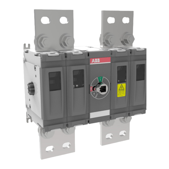
- Page 1 — I N S TA L L AT I O N I N S T R U C T I O N DC switch disconnectors OTDC800...1000F_/OTDC800...1000UF_...
-
Page 2: Table Of Contents
D C S W I T C H D I S C O N N E C T O R S — Table of contents Use of symbols Receiving, handling and storage Read this safety instructions carefully before using this product Circuits 07 −... -
Page 3: Use Of Symbols
D C S W I TC H D I S C O N N E C TO R S — Use of symbols Hazardous voltage Caution Warns about a situation where a hazardous Provides important information or warns voltage may cause physical injury to a about a situation that may have a detrimen- person or damage to equipment. -
Page 4: Receiving, Handling And Storage
If damage is evident, or there is visible indication of rough handling, Warning immediately file a damage claim with the transportation company, and notify your local ABB sales office. HAZARD OF EQUIPMENT Do not remove the shipping package until OVERTURNING ready to install the switch. -
Page 5: Read This Safety Instructions Carefully Before Using This Product
D C S W I TC H D I S C O N N E C TO R S — Read these safety instructions carefully before using this product! HAZARD OF ELECTRIC SHOCK, EXPLOSION, OR ARC FLASH • Apply appropriate personal protective equipment and follow safe electrical work practices. -
Page 6: Circuits
D C S W I T C H D I S C O N N E C T O R S — Circuits Circuit 6c, 6g 4-pole, 4-wire 4-pole, 4-wire 1-circuit 1-circuit REVERSED SUPPLY SUPPLY + ( – ) – ( + ) LOAD OEZXY OEZXY... -
Page 7: Enclosure Dimensioning
D C S W I TC H D I S C O N N E C TO R S — Enclosure dimensioning Clearances per UL98 / IEC 60947 mm / in Warning 25,4 1.00 A minimum distance of 50,8 1.38 1.38 25,4 mm (1 in) 2.00... - Page 8 D C S W I T C H D I S C O N N E C T O R S — Enclosure dimensioning Clearances per UL98 / IEC 60947 mm / in 25,4 1.00 Warning A minimum distance of 50,8 2.00 25,4 mm (1 in)
-
Page 9: Mounting Otdc_F
D C S W I TC H D I S C O N N E C TO R S — Mounting OTDC_F_ TORX T20 2,2 Nm 20 lb.in 360o 360o CAUTION Magnetic field Exceeds 5 Gauss Warning Within 15cm / 6 inch of surface. -
Page 10: Busbars And Compression Lugs
D C S W I T C H D I S C O N N E C T O R S — Busbars and compression lugs M10 30...44 Nm / 266-390 lb.in M12 50...75 Nm / 443-664 lb.in Caution Always use counter torque when tightening terminals! 76,2 Max. - Page 11 D C S W I TC H D I S C O N N E C TO R S — Busbars and compression lugs Busbar width [ mm / in ] 76,2 / 3 Minimum Busbar cross-section acc. to UL98B [ mm2 ] ∅D 800 A...
-
Page 12: Connection Bar Kit Otdckit800Fs11
D C S W I T C H D I S C O N N E C T O R S — Connection bar kit OTDCKIT800FS11 4× 8× OTDCKIT800FS11 50...75 Nm 443-664 lb.in Circuit 6c, 6g OTDC800F22 OTDC800FV22 OTDC800UF22 OTDC800UFV22 OTDC1000F22 OTDC1000FV22 OTDC1000UF22... -
Page 13: Connection Bar Kit Otdckit800Fs12
D C S W I TC H D I S C O N N E C TO R S — Connection bar kit OTDCKIT800FS12 12× 8× 6× 4× OTDCKIT800FS12 50...75 Nm 443-664 lb.in Circuit 6N OTDC800UF23 OTDC800UFV23 Caution Installation only as shown in drawings. -
Page 14: Mechanical Lug Kit Ozxa804
D C S W I T C H D I S C O N N E C T O R S — Mechanical lug kit OZXA804 4× 4× Caution 56,5 Nm Always use counter torque when 500 lb.in tightening terminals! M12x25 54,2 Nm 480 lb.in... -
Page 15: Direct Handle Kit Otdv400Fk
D C S W I TC H D I S C O N N E C TO R S — Direct handle kit OTDV400FK_ 0.8 Nm OTDV400FK2 7.1 lb.in 1.2 Nm 11 lb.in Ø 5-6 mm 0.20-0.24 in Remove Information Use protection against direct contact. -
Page 16: Auxiliary Contacts Oa
D C S W I T C H D I S C O N N E C T O R S — Auxiliary contacts Test contact max. 4 pcs Remove Test ∼10∘ max 2 Main contact max 2 Test contact (NO) NO: OA1G10 max 2 NC: OA3G01... - Page 17 D C S W I TC H D I S C O N N E C TO R S — Dimension drawings OTDC800-1000_F_22 mm / in 4.882 3.150 1.496 1.929 19,5 1.535 1.181 0.768 0.315 17,5 49,5 0.689 1.949 0.512 0.020 0.295 9.055...
- Page 18 D C S W I T C H D I S C O N N E C T O R S — Dimension drawings OTDC800-1000_F_23 mm / in 12.402 4.882 6.811 3.110 1.969 24,5 1.929 0.965 0.197 ∅13 0.512 0.295 5.32 44,43 1.749...
-
Page 19: Dimension Drawings
D C S W I TC H D I S C O N N E C TO R S — Dimension drawings Connection bar kit OTDCKIT800FS11 OTDCKIT800FS12... - Page 20 — Contact us ABB Oy P.O. Box 622 FI-65101 Vaasa Finland abb.com/lowvoltage © Copyright 2021 ABB. All rights reserved. Specifications subject to change without notice.