Pioneer DDJ-T1 Service Manual
Dj controller
Hide thumbs
Also See for DDJ-T1:
- Service manual (135 pages) ,
- Operating instructions manual (96 pages) ,
- Operating instruction (92 pages)
Table of Contents
Quick Links
DJ CONTROLLER
DDJ-T1
THIS MANUAL IS APPLICABLE TO THE FOLLOWING MODEL(S) AND TYPE(S).
Model
Type
DDJ-T1
SVYXJ8
DDJ-T1
UXJCB
DDJ-T1
FLPXJ
DDJ-T1
KXJ5
DDJ-T1
AXJ5
For details, refer to "Important Check Points for good servicing".
PIONEER CORPORATION
PIONEER ELECTRONICS (USA) INC. P.O. Box 1760, Long Beach, CA 90801-1760, U.S.A.
PIONEER EUROPE NV Haven 1087, Keetberglaan 1, 9120 Melsele, Belgium
PIONEER ELECTRONICS ASIACENTRE PTE. LTD. 253 Alexandra Road, #04-01, Singapore 159936
PIONEER CORPORATION
Power Requirement
AC 100 V to 240 V
AC 100 V to 240 V
AC 100 V to 240 V
AC 100 V to 240 V
AC 100 V to 240 V
1-1, Shin-ogura, Saiwai-ku, Kawasaki-shi, Kanagawa 212-0031, Japan
2011
DDJ-T1
K-IZV FEB.
ORDER NO.
RRV4164
Remarks
2011 Printed in Japan
Table of Contents

Related Manuals for Pioneer DDJ-T1


Summary of Contents for Pioneer DDJ-T1
- Page 1 PIONEER CORPORATION 1-1, Shin-ogura, Saiwai-ku, Kawasaki-shi, Kanagawa 212-0031, Japan PIONEER ELECTRONICS (USA) INC. P.O. Box 1760, Long Beach, CA 90801-1760, U.S.A. PIONEER EUROPE NV Haven 1087, Keetberglaan 1, 9120 Melsele, Belgium PIONEER ELECTRONICS ASIACENTRE PTE. LTD. 253 Alexandra Road, #04-01, Singapore 159936...
- Page 2 PIONEER Service Manual. A subscription to, or additional copies of, Also test with plug reversed Earth PIONEER Service Manual may be obtained at a nominal (Using AC adapter ground charge from PIONEER. plug as required)
- Page 3 To protect products from damages or failures during transit, the shipping mode should be set or the shipping screws should be installed before shipment. Please be sure to follow this method especially if it is specified in this manual. DDJ-T1...
-
Page 4: Table Of Contents
11.5 TCHB, JOGB and LEDB ASSYS ..........................108 11.6 CDJ1B ASSY ................................112 11.7 CDJ2B ASSY ................................116 11.8 DJMB ASSY................................120 11.9 CHFD and CRFD ASSYS ............................124 11.10 MICB ASSY................................128 11.11 HPJK ASSY ................................129 11.12 USBB ASSY................................130 12. PCB PARTS LIST ................................131 DDJ-T1... -
Page 5: Service Precautions
After the EEPROM is replaced, be sure to copy the program for the USB controller to it. For details, see “8.4 Copying the Program for the USB Controller.” Replacement of the MAIN_UCOM When replacement of the MAIN_UCOM (IC701) is required, order a microcomputer dedicated for service (PEG850A8-K). DDJ-T1... -
Page 6: Specifications
S/ N ratio (when playing on computer) without notice. MASTER OUT 1..103 dB or greater (at rated output) MASTER OUT 2..103 dB or greater (at rated output) Accessories • TRAKTOR Pioneer DDJ-T1 EDITION software CD-ROM • AC adapter (DXX2665) (DWR1491) • Driver software CD-ROM (DXX2666) •... -
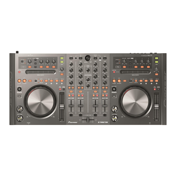
Page 7: Panel Facilities
2.2 PANEL FACILITIES Rear panel Front panel DDJ-T1... - Page 8 Control panel DDJ-T1...
- Page 9 1 Browser DDJ-T1...
- Page 10 2 Deck DDJ-T1...
- Page 11 3 Mixer DDJ-T1...
- Page 12 4 Effect DDJ-T1...
-
Page 13: Basic Items For Service
Purpose of use / Remarks USB cable GGP1188 for PC connection, accessory AC adapter DWR1491 Accessory (Note: The power plug part is different.) Lubricants and Glues List Name Part No. Remarks Lubricating oil GYA1001 Refer to “9.5 JOG SECTION”. DDJ-T1... -
Page 14: Pcb Locations
2..CDJ1B ASSY DWS1430 1..DJM2 ASSY DWM2426 2..JOGB ASSY DWS1432 2..DJMB ASSY DWX3211 2..TCHB ASSY DWS1433 2..JACB ASSY DWX3214 2..LEDB ASSY DWS1434 2..USBB ASSY DWX3222 1..CDJ2 ASSY DWM2423 2..CDJ2B ASSY DWS1431 2..JOGB ASSY DWS1432 2..TCHB ASSY DWS1433 2..LEDB ASSY DWS1434 DDJ-T1... - Page 15 DDJ-T1...
-
Page 16: Block Diagram
DJMB ASSY HP_L DDD1547- 1mm pitch / GND_AH L=100mm/TAPE LENGTH=8mm,1 MUTE (DWX3211) K M 2 0 0 N A 9 C N 4 8 0 1 JA4801 HPJK ASSY HP OUT DKN1622- OP AMP (DWX3216) JA4802 HP OUT (mini) CKS4124- DDJ-T1... - Page 17 K M 2 0 0 N A 3 L MIC IN MICB ASSY JA4601 OP AMP DKN1614- K M 2 0 0 N A 3 L PF03PP-C06 2mm pitch C N 4 3 0 1 (DWX3215) L=60mm GND_AD CRFD ASSY AD_CROSSF V+3R3_AD (DWX3213) DDJ-T1...
-
Page 18: Overall Block Diagram
Key In [12:9][4:1] Grid[7:4] IC1101 Key Buffer Key In[8:5] Key In[13][8:5] IC1102 Key Buffer CN6002 JH6001 LED[11:6] CN3201 CN3301 IC301 IC303 AUX/MIC CN3503 IC302 CDJ2B ASSY TCHB ASSY JOGB ASSY CN4001 CN4601 VR4601 JA4601 MIC IN IC4601 AUX/MIC SW MICB ASSY DDJ-T1... - Page 19 CN6002 JOG1_1/1_2 CN3301 CN3201 IC106 CN3003 Reset IC IC303 AUX/MIC Fault_Det Circuit CDJ1B ASSY Trim Fader TCHB ASSY JOGB ASSY CN4301 CN4001 CN4002 MATRIX Circuit CHFD ASSY FD SATRT SW MATRIX Circuit CN4202 CN2001 CRFD CRFD ASSY DJMB ASSY DDJ-T1...
-
Page 20: Power Block Diagram
5V→3.3V S-1200B33 V+5_D V+5_A IC101 IC103 D/D_CONV 5V_REG 5V→6V 6V→5V BD9851EFV S-1200B50 AUDIO AMP(MASTER) RNB4580F V+5_D IC101 IC501 D/D_CONV 5V→-6V BD9851EFV AUDIO AMP(HP) NJM4565MD IC305 SW AMP(AUX/MIC) NJM2121MD x2 IC301, IC302 OPAMP x1 OPAMP x4 JACB ASSY MICB ASSY DDJ-T1...