
Related Manuals for Bosch DX Series


Summary of Contents for Bosch DX Series
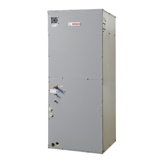
- Page 1 Unitary Air Handler AHU Series Installation and Maintenance Manual DX AND HYDRONIC SERIES 6720220327 Revised 11-11...
-
Page 2: Table Of Contents
00 - NO ELECTRIC HEAT 05 - 5KW ELECTRIC HEAT 10 - 10KW ELECTRIC HEAT 15 - 15KW ELECTRIC HEAT 20 - 20KW ELECTRIC HEAT 6720220327 Subject to change without prior notice Revised 11-11 ©Copyright 2011 Bosch, Inc All rights reserved... -
Page 3: Physical Data
Physical Data Unitary Air Handler DX and Hydronic Series Physical Data Table 1: DX UNITS DX025 DX035 DX049 DX061 DX071 Nominal Capacity (Tons) Refrigerant Type R410A Liquid Line Connection Size (in) Suction Line Connection Size (in) Standard Filter Size 16 x 20 x 2 20 x 20 x 2 20 x 24 x 2 20 x 24 x 2... -
Page 4: Dimensional Data
Unitary Air Handler DX and Hydronic Series Dimensional Data DIMENSIONAl DAtA fOR DX UNItS DIMENSIONAl DAtA MUltI-POSItION AIR HANDlER COOl ONlY OR ElECtRIC HEAt Model DX025 17.50 43.00 21.00 15.50 12.50 13.50 11.00 6.75 16.75 14.00 11.00 10.75 2.00 1.50 5.00 DX035 21.00 48.00 21.00 19.00 12.50 14.50 13.00 6.75... - Page 5 Unitary Air Handler DX and Hydronic Series Dimensional Data DIMENSIONAl DAtA fOR HYDRONIC AIR HANDlERS DIMENSIONAl DAtA MUltI-POSItION AIR HANDlER HYDRONIC HEAt Model HY025 17.50 43.00 21.00 15.50 12.50 13.50 11.00 6.75 16.75 16.25 13.50 10.75 8.25 4.75 2.00 4.00 8.75 2.00 HY035 21.00 48.00 21.00 19.00 12.50 15.50 13.00 6.75 20.25 19.75 14.25 12.75 10.25 7.50 2.25...
-
Page 6: General Information
Unitary Air Handler DX and Hydronic Series General Information GENERAl INfORMAtION SAfEtY CONSIDERAtIONS This single piece air handler provides the flexibility Installation and servicing of this equipment can be for installation in any upflow, downflow, or hazardous due to system pressure and electrical horizontal application. -
Page 7: Location
1. Allow sufficient room for the removal of the filter to comply with National codes and/or prevailing and access panels, and has enough room for local codes and regulations. BOSCH Group service personnel to perform maintenance or assumes no responsibility for units installed in repair. -
Page 8: Minimum Clearances
Unitary Air Handler DX and Hydronic Series Minimum Clearances unit. The unit can be serviced entirely from the non-conditioned space to prevent damage from front, including replacing the filter. Be sure to route condensation runoff. It is recommended that primary and secondary condensate drain piping so units installed in non-conditioned spaces be as not to obstruct replacement of filter. -
Page 9: Downflow Application
(See Figure 1) are available from Bosch as an accessory (Part # 930-004 or 4. Reinstall the cooling coil. 930-006). If the hanging bracket kit is purchased 5. Connect the condensate drains and refrigerant from Bosch, always refer to the hanging bracket lines. -
Page 10: Downflow Conversion Kit
10 Unitary Air Handler DX and Hydronic Series Downflow Conversion Kit 9. Re-install the blower and control box access 2. Slide the evaporator assembly back into the coil door in the upside down position and secure section. Evaporator must be installed so it is with the screws that were removed in Step 1. -
Page 11: Furnace Installation
furnace Installation Unitary Air Handler DX and Hydronic Series A. If the Combustible Floor Base is used you secure the furnace to the floor by drilling two holes through the furnace base and the floor base at the right and left front inside corners of the cabinet. -
Page 12: Field Installed Electric Heater Kits
12 Unitary Air Handler DX and Hydronic Series Electric Heater Kits 13. Tighten the screws on the cable connectors Follow the steps below to connect the power until the power supply wires are securely supply wires. fastened to the connector. Single Circuit line Wiring Connections The 15kW and 20kW models may be connected to a single or dual branch circuit. -
Page 13: Variable Speed Motor
Unitary Air Handler DX and Hydronic Series variable Speed Motor need to be installed. Follow the “Power Supply The field installed electric heat accessories are Wiring” instructions for proper installation. used on cooling or heat pump models that were not purchased with electric heat from the factory. -
Page 14: Ecm Interface Board & Thermostat Connections
Caution light powered off of the common (C) side of the 12. Connect the same two cables that were transformer, the unit must be provided with a removed in step 3. malfunction relay (Bosch option # 660-006) to 13. Slide the blower assembly into the blower deck, properly energize the light. The relay coil will be replace the angle bracket, insert the screws wired across the (ALR) and (C) contacts on the through the holes in the angle bracket and unit’s UPM board and the relay’s normally open... -
Page 15: Control Wiring
Unitary Air Handler DX and Hydronic Series Control Wiring To the left of the motor control board are a row of If the motor ramps up to 100% power, then the 3 red and 4 green LED’s. These LED’s indicate the motor itself is functioning normally. -
Page 16: Condensate Drain
16 Unitary Air Handler DX and Hydronic Series Condensate Drain unit is used with this air handler, use a thermostat with isolating contacts to prevent inter-connection of two separate Class 2 circuits (RC terminal is used for the condensing section unit and RH terminal is used for the air handler. -
Page 17: Piping
Bosch condensing section units are supplied then oil traps are required at equal intervals along the with either a copper or optional cupro-nickel suction line. -
Page 18: Water Piping
18 Unitary Air Handler DX and Hydronic Series Water Piping temperature does not exceed 150°F. It is Pressure drop in liquid must not exceed 30 psi recommended that the water shut-off valve for the or erratic operation and thermostatic expan- water heater be located close to the water heater. sion damage will occur. Isolation valves are also recommended. WAtER PIPING It is recommended that any devices installed, which could create a closed system, have a by-... -
Page 19: Check Test And Start Up
Unitary Air Handler DX and Hydronic Series Check test and Start Up Installation Steps: 1. After coil pressure has been relieved, turn the female swivel nut counter-clockwise to remove. 2. Remove the piston from the flowrator distributor fitting using a small diameter wire or paper clip. -
Page 20: System Shut Down
DY AUTO boiler source. Contact Bosch for ratings and CHANGEOVER CONTROLLER capacities for boiler system use. (Bosch Part #:7 738 000 397). SYStEM SHUt-DOWN This accessory is only needed for a HY air Caution handler with a paired water-to-water unit with a For short periods of time during freezing unit mounted controller. If your water-to-water... - Page 21 Unitary Air Handler DX and Hydronic Series Connecting Controller thermostat to the “O” & “C” connections on the When installing the Auto Changeover Controller. If a DDC controller controller, locate the four with a dry contact is to be used then route wires holes provided in the from the “DRY”...
-
Page 22: Performance Tables
22 Unitary Air Handler DX and Hydronic Series Performance tables fUll lOAD “Y1 + Y2” blOWER PERfORMANCE - DX UNItS VOLTS, 1 NOMINAL MOTOR BLOWER MODEL PH 50/60 JUMPER TONS WHEEL 0.1" 0.2" 0.3" 0.4" 0.5" 0.6" 0.7" 0.8" 0.9" 1.0"... -
Page 23: Motor Control Board Settings
Unitary Air Handler DX and Hydronic Series Motor Control board PAIRED WITH TA CONDENSING SECTION PAIRED WITH CE CONDENSING SECTION MOTOR MOTOR BOARD BOARD UNIT PART FULL JUMPERS PART FULL JUMPERS LOAD LOAD SETTING FOR ADJUSTMENT LOAD LOAD SETTING FOR ADJUSTMENT NORMAL SETTING... -
Page 24: System Piping Schematics
24 Unitary Air Handler DX and Hydronic Series Piping Schematics SYStEM PIPING SCHEMAtICS ClOSED lOOP – GROUND lOOP SYStEM WItH GEOtHERMAl StORAGE tANK RESIDENtIAl APPlICAtION OPEN SYStEM – GROUND WAtER SYStEM WItH GEOtHERMAl StORAGE tANK RESIDENtIAl APPlICAtION 6720220327 Subject to change without prior notice Revised 11-11... -
Page 25: Electrical Data
Electrical Data Unitary Air Handler DX and Hydronic Series ElECtRICAl DAtA Electrical Data Minimum Circuit Maximum Overcurrent Motor Data Electric Heater Data Ampacity Protection Amps Amps Amps Amps MOCP MOCP MOCP MOCP Model Amps # of 208 V 208 V 240 V 240 V 208 V... -
Page 26: Electrical Diagrams
26 Unitary Air Handler DX and Hydronic Series Electrical Diagrams ElECtRICAl DIAGRAMS Air Handler without Electric Heat 6720220327 Subject to change without prior notice Revised 11-11... - Page 27 Unitary Air Handler DX and Hydronic Series Electrical Diagrams ElECtRICAl DIAGRAMS 5Kw Electric Heater Package Revised 11-11 Subject to change without prior notice 6720220327...
- Page 28 28 Unitary Air Handler DX and Hydronic Series Electrical Diagrams ElECtRICAl DIAGRAMS 10Kw Electric Heater Package 6720220327 Subject to change without prior notice Revised 11-11...
- Page 29 Electrical Diagrams Unitary Air Handler DX and Hydronic Series ElECtRICAl DIAGRAMS 15Kw Electric Heater Package Revised 11-11 Subject to change without prior notice 6720220327...
- Page 30 30 Unitary Air Handler DX and Hydronic Series typical Wiring Diagrams ElECtRICAl DIAGRAMS 20Kw Electric Heater Package 6720220327 Subject to change without prior notice Revised 11-11...
-
Page 31: Unit Check-Out Sheet
Model Number _________________________________________________ Serial Number ________________________ Max Fuse Size (Amps) __________________________________________ Volts / Amps ____________________________________________________ Entering Air Temperature _______________________________________ Leaving Air Temperature Bosch group 601 N.W. 65th Court, Ft. Lauderdale, FL 33309 Phone: 954-776-5471 Fax: 954-776-5529 www.fhp-mfg.us Revised 11-11 Subject to change without prior notice... - Page 32 601 N.W. 65th Court, Ft. Lauderdale, FL 33309 Phone: 954-776-5471 | Fax: 954-776-5529 www.boschtaxcredit.com | www.bosch-climate.us...