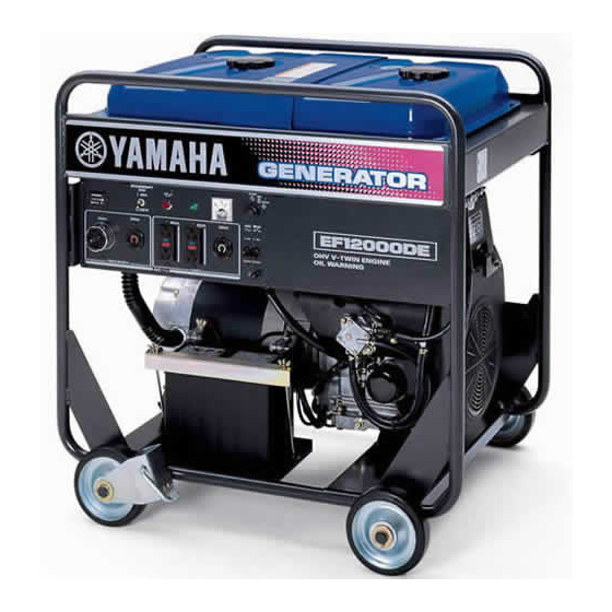
Yamaha EF12000DE Owner's Manual
Hide thumbs
Also See for EF12000DE:
- Owner's manual (53 pages) ,
- Theory & diagnostics manual (218 pages)

Related Manuals for Yamaha EF12000DE


Summary of Contents for Yamaha EF12000DE
- Page 1 Generator OWNER’S MANUAL Read this manual carefully before operating this machine. EF12000DE LIT-19626-02-08 7UX-28199-1B...
- Page 3 INTRODUCTION Congratulations on your purchase of your new Yamaha. This manual will provide you with a good basic understanding of the operation and maintenance of this machine. If you have any questions regarding the operation or maintenance of your machine, please consult a Yamaha dealer.
- Page 4 BEFORE OPERATING THE MACHINE. 851-005 Particularly important information is dis- tinguished in this manual by the follow- 9 Yamaha continually seeks advance- ing notations. ments in product design and quali- ty. Therefore, while this manual contains the most current product information available at the time of This is the safety alert symbol.
- Page 5 Check that following acces- sories come with your Yamaha Generator. (1) Owner’s manual (2) Wheel mounting parts (See page 39.) (3) Servicing tools (4) Battery mounting bracket (See page 13.) Be sure to replenish with engine oil. (See page 10 for details.) NOTICE The generator has been shipped without engine oil.
- Page 6 Symbols and Meanings In accordance with the European requirements (eec Directives), the specified symbols as shown in the following table are used for the products and this instruction manual.
-
Page 7: Table Of Contents
CONTENTS LOCATION OF IMPORTANT LABELS ..........1 SAFETY INFORMATION ................2 EXHAUST FUMES ARE POISONOUS..........3 FUEL IS HIGHLY FLAMMABLE AND POISONOUS .......3 ENGINE AND MUFFLER MAY BE HOT ...........4 ELECTRIC SHOCK PREVENTION ..........4 CONNECTION NOTES ..............5 CONNECTION...................5 EXTENSION CORD NOTES .............5 CONTROL FUNCTION ................7 PRE-OPERATION CHECK..............10 CHECK ENGINE OIL ..............10 CHECK FUEL..................11... - Page 8 CHECKING CARBON BRUSH ............30 BATTERY-Replenishing the battery fluid........31 SPARK ARRESTER ................32 PREPARATION FOR STORAGE............33 HIGH ALTITUDE ENGINE OPERATION ........34 BATTERY ..................34 TROUBLESHOOTING ................35 SPECIFICATIONS ................36 CONSUMER INFORMATION ...............37 WIRING DIAGRAM ................38 OPTIONAL PARTS ................39 "HOW-TO" INSTALL THE WHEEL..........39 YAMAHA EXTENDED SERVICE (Y.E.S.) ..........40...
-
Page 9: Location Of Important Labels
REFER TO OWNER'S MANUAL FOR MAINTENANCE SPECIFICATIONS AND ADJUSTMENTS. THIS ENGINE MEETS EMISSION STANDARDS FOR **** U.S. EPA REGULATIONS FOR SMALL NON-ROAD ENGINES (EMISSION COMPLIANCE PERIOD OF 1000 HOURS) AND CALIFORNIA SI SORE's. **** YAMAHA MOTOR POWERED PRODUCTS CO.,LTD. EH63 .64 .65 − 1−... -
Page 10: Safety Information
G-380 SAFETY INFORMATION 9 This generator is not designed for on-board use. Do not use it while installed on the vehi- cle. 9 Do not modify the generator or use it with its parts removed. 9 Do not allow children to operate the generator. 9 Be sure to carry the generator only by its carry- ing handle(s). -
Page 11: Exhaust Fumes Are Poisonous
G-381 EXHAUST FUMES ARE POISONOUS 9 Using a generator indoors CAN KILL YOU IN MINUTES. Generator exhaust contains car- bon monoxide. This is a poison you cannot see or smell. 9 NEVER use inside a home or garage, EVEN 743-002 IF doors and windows are open. -
Page 12: Engine And Muffler May Be Hot
G-383 ENGINE AND MUFFLER MAY BE HOT 9 Place the machine in a place where pedestri- ans or children are not likely to touch the machine. 743-006 9 Avoid placing any flammable materials near the exhaust outlet during operation. 743-007 9 In order to prevent overheating, ensure adequate airflow by keeping the machine at least 1 m (3 ft) from objects or other equipment. -
Page 13: Connection Notes
9 Connect the Ground (earth) terminal to a ground source. In order to prevent electrical shock, the generator must be grounded when using an electrical device with a ground plug. 1 Ground (earth) terminal G-385 CONNECTION NOTES 9 Avoid connecting the generator to commercial power outlet. - Page 14 Notes on installation 1. If you provide the generator with wheels, always be sure to place the genera- tor on a level surface, locking the wheel with the stopper and / or chocking the wheels. 2. Select a place that allows you to maintain and inspect the generator, which is not exposed to contamination by exhaust gas.
-
Page 15: Control Function
CONTROL FUNCTION FUEL GAUGE TANK CAP FUEL TANK AIR CLEANER CONTROL PANEL BATTERY FUEL COCK STOPPER OIL FILLER CAP OIL FILTER SPARK PLUG CAP MUFFLER SPARK PLUG OIL GAUGE ELECTRIC STARTER OIL DRAIN PLUG CONNECTOR FOR REMOTE CONTROL − 7−... - Page 16 − 8−...
- Page 17 When the starter switch is turned to the "START" from the "STOP" position, the oil pressure warning lamp flashes only once to check the bulb. If it does not flash, ask a Yamaha dealer to inspect the electrical circuit. Fail-safe Function of ECU (Electronic Control Unit)
-
Page 18: Pre-Operation Check
PRE-OPERATION CHECK CHECK ENGINE OIL OIL GAUGE Before checking or refilling oil, be sure gener- ator is located on stable and level surface with engine stopped. UPPER LEVEL 1) Remove oil level gauge and check the engine oil level. 2) If oil level is below the lower level line on the oil gauge, refill with suitable oil (see table) to upper level after removing the LOWER... -
Page 19: Check Fuel
CHECK FUEL WARNING Do not refuel while smoking or near open flame or other such potential fire hazards. Otherwise fire accident may occur. 1) Check fuel level at fuel level gauge. Tank cap 2) If fuel level is low, refill with unleaded Fuel gauge Fuel filter screen automotive gasoline. - Page 20 Fuel Amount EMPTY FULL up to "LEVEL" position 38 L (10.04 US gal, 8.36 Imp gal) "LEVEL" MARK he full level of fuel is the upper surface of the fuel filter. Be sure to add the fuel in small amounts as the fuel level approaches to the full fuel level mark.
-
Page 21: Battery Installation
AE00231 BATTERY (See page 31 for more details) Check the fluid level and fill if necessary. Use only distilled water if refilling is necessary. Recommended Battery ・ h or larger. Lead-acid battery : A capacity of 12V-32A For the generators used in low temperature below -5˚C(23˚F), 12V-40A ・... - Page 22 ① RED CABLE ③ ④ ② LESS THAN ① Butterfly nut ┓ 205 mm ② Long bolt ┣ Accessory ( 8.1 in ) ③ Supporting arm ┛ parts ④ Terminals and nut LESS THAN LESS THAN 170 mm ( 6.7 in ) 260 mm ( 10.2 in ) RED CABLE Red cable: to the positive (+) terminal...
-
Page 23: Check Component Parts
CHECK COMPONENT PARTS Check following items before starting engine: Fuel leakage from fuel hose, etc. Bolts and nuts for looseness. Components for damage or breakage. Generator not resting on or against any adjacent wiring. CHECK GENERATOR SURROUNDINGS WARNING Make sure you review each warning in order to prevent fire hazard. Keep area clear of inflammables or other hazardous materials. -
Page 24: Operation
OPERATION STARTING THE ENGINE NOTICE Check the oil level before each operations. (See page 10) Perform the specified daily inspection to see if it is in normal condition. (1) Make sure that the economy switch O M Y and AC switch (no-fuse breaker) are E C O N off. -
Page 25: Using Electric Power
In the following occasion, two or three trials may be required for starting the engine : (1) The very first starting of a new generator. (2) After the refueling of the engine which has been stopped due to fuel short- age. - Page 26 (1) AC APPLICATION (a) Ground the generator, using the ground terminal located at the side of the panel. 1 Ground (Earth) terminal (b) Before starting the engine, check that O M Y the economy switch and AC switch of E C O N the generator and the power switches of the appliances are turned off.
- Page 27 Style Ampere Receptacle AC plug Description G.F.C.I. (Ground Fault NEMA NEMA Circuit Interrupter) up to 20A Receptacle, duplex 5-20R 5-20P (REC1) NEMA NEMA Locking Receptacle up to 30A L5-30R L5-30P (REC2) NEMA NEMA Locking Receptacle up to 30A L14-30R L14-30P (REC3) HUBBELL HUBBELL...
- Page 28 Stop the generator immedi- ately, check the appliance and / or gen- erator for overloading or detect and have repaired as necessary by Yamaha dealer or service shop. − 20−...
- Page 29 ECONOMY SWITCH ECONOMY SWITCH automatically reduces engine speed when load is OFF, and automatically increases engine speed to rated r/min when load is ON. ECONOMY SWITCH provides fuel economy and low noise operation at no-load running. (1) HOW TO USE ECONOMY SWITCH O M Y E C O N Start the engine with ECONOMY...
-
Page 30: Stopping The Generator
STOPPING THE GENERATOR (1) Turn off the power switch of the elec- O M Y tric equipment. E C O N (2) Turn the economy switch and AC switch (no-fuse breaker) to off. (3) Unplug the cord from receptacle of the O F F O F F O F F... -
Page 31: Wattage Information
WATTAGE INFORMATION Some appliances need a "surge" of energy when starting. This means that the amount of electrical power needed to start the appliance may exceed the amount needed to maintain its use. Electrical appliances and tools normally come with a label indicating voltage, cycles/Hz, amperage (amps) and electrical power needed to run the appliance or tool. -
Page 32: Voltage Drop In Electric Extension Cords
To determine the total wattage required to run a particular electrical appliance or tool, multiply the voltage figure of the appliance/tool by the amperage (amps) fig- ure of same. The voltage and amperage (amps) information can be found on a name plate which is normally attached to electrical appliances and tools. -
Page 33: Maintenance Schedule
MAINTENANCE SCHEDULE DAILY INSPECTION Before running the generator, check the following service items: Safe surroundings Leakage of gasoline and engine oil Clean air cleaner element Enough gasoline Excessive vibration, noise Enough clean engine oil Loose or broken bolts and nuts PERIODIC MAINTENANCE Periodic maintenance is vital to safe and efficient operation of your generator. - Page 34 *Note 2 : As to the procedures for these items, please refer to the SERVICE MANUAL or consult your nearest Yamaha dealer. *Note 3 : More frequent oil changing, oil filter replacement and air cleaner service on replacement may be necessary depending on operating conditions.
-
Page 35: How-To" Maintenance
"HOW-TO" MAINTENANCE ENGINE OIL CHANGE OIL DRAIN PLUG Initial oil change (ON BOTH SIDE) ・ ・ ・ ・ ・ After 20 hours of operation Thereafter ・ ・ ・ ・ ・ Every 100 hours of operation 1. When changing oil, stop the engine and remove the drain plug. -
Page 36: Servicing Air Cleaner
SERVICING AIR CLEANER A dirty air cleaner element will cause KNOB AIR CLEANER COVER starting difficulty, power loss, engine mal- functions, and shorten engine life extremely. Always keep the air cleaner element clean. Replace the air cleaner element set more often in dusty environments. The air cleaner paper inner element and urethane foam outer element can be removed after removing knob and air... -
Page 37: Cleaning And Adjusting Spark Plug
CLEANING AND ADJUSTING SPARK PLUG (a) Unplug the high-voltage cables (locat- ed at the outlet panel and lead-acid battery). (b) Using the supplied plug wrench and 0.7–0.8 mm handle, turn it counterclockwise until it (0.028–0.031 in) comes off. (c) Clean the area around the mounting hole. -
Page 38: Fuel Hose Replacement
FUEL HOSE REPLACEMENT WARNING Take extreme caution when replacing fuel hose ; gasoline is flammable. Replace the fuel hose every 1,000 hours or every 2 years. If fuel hose leak is found, replace the fuel hose immediately. CHECKING CARBON BRUSH BRUSH If the brush become excessively worn, its HOLDER... -
Page 39: Battery-Replenishing The Battery Fluid
AE00481 BATTERY Replenishing the battery fluid 1. Check the fluid level. The level should be between the upper and lower level marks. 1 Upper level 762-035 2 Lower level 2. Add only distilled water if necessary. NOTICE Normal tap water contains minerals which are harmful to a battery;... -
Page 40: Spark Arrester
SPARK ARRESTER SPARK ARRESTER In a dry or wooded area, it is recommendable to use the engine with a spark arrester. Some areas require the use of a spark arrester. Please check your local laws and regulations before operating your engine. The spark arrester must be cleaned regularly to keep it functioning as designed. -
Page 41: Preparation For Storage
PREPARATION FOR STORAGE The following procedures should be followed prior to storage of your generator for a period of 6 months or longer. WARNING Fuel is highly flammable and poisonous. Check "SAFETY INFORMATION" (See page 3) carefully. NOTICE Immediately wipe off spilled fuel with a clean, dry, soft cloth, since fuel may deteriorate painted sur-faces or plastic parts. -
Page 42: High Altitude Engine Operation
HIGH ALTITUDE ENGINE OPERATION Please have an authorized Yamaha dealer modify this engine if it is to be run con- tinuously above 5000 feet (1500 meters). Failure to do so, may result in poor engine performance, spark plug fouling, hard starting, and increased emissions. -
Page 43: Troubleshooting
If your generator still fails to start or generate electricity, con- tact your nearest Yamaha dealer or authorized service center for further informa- tion or corrective procedures. -
Page 44: Specifications
SPECIFICATIONS Model EF12000DE Type Brush, Self-exciting, 2-pole, Single phase Rated frequency 60 Hz Rated voltage 120V / 240V Rated current 79.2 A / 39.6 A Rated output 9500 VA Maximum output 12000 VA Power factor Voltage regulator A.V.R type Model... -
Page 45: Consumer Information
Record your Primary I.D., and serial MODEL numbers in the spaces provided, to assist you in ordering spare parts from a PRI-I.D. Yamaha dealer. SERIAL No. CODE Also record and keep these I.D. num- bers in a separate place in case your machine is stolen. -
Page 46: Wiring Diagram
WIRING DIAGRAM CONTROL BOX Auto choke LGrn ( Bimetal ) Fuel cut Oil pressure warning lamp ( Red ) Blk/W Blk/W Ignition coil (AC output) Idle solenoid Electronic control unit LBlu 9 8 7 Idle control unit Charge Exciting Grn/Y coil coil Economy... -
Page 47: Optional Parts
OPTIONAL PARTS "HOW-TO" INSTALL THE WHEEL 1) Checking of supplied accessories (2) Tool preparation Hoist or square bar (100 mm (3.94 in) by 100 mm (3.94 in), length : 700 mm (27.56 in)) Pliers Spanner or socket wrench (12 mm (0.472 in)), 2 units (3) Installation procedures (a) Raise the generator by about 100 mm (3.94 in), with hoist or with square bar put under the bottom panel. -
Page 48: Yamaha Extended Service (Y.e.s.)
9 Y.E.S. is flexible. You can choose the plan that’s right for you: 12 months, 24 months or 36 months coverage. 9 Y.E.S. is administered by the same Yamaha people that handle your warranty - and it shows in the comprehensive coverage benefits. There are no hour limitations and Y.E.S. covers manufacturing defects just like your warranty. - Page 50 3ZZ9020248 ISSUE EMD-WS7700 PRINTED IN JAPAN 2014.05×2 ! PRINTED ON RECYCLED PAPER...