Sharp FO-71 /51/11 Service Manual
Hide thumbs
Also See for FO-71 /51/11:
- Operation manual (162 pages) ,
- Service manual (89 pages) ,
- Operation manual (83 pages)
Table of Contents
Quick Links
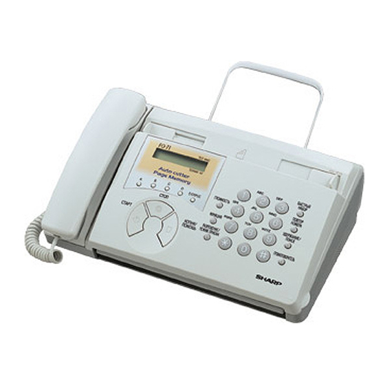
Illustration: FO-71TH
[1] Specifications ............................................ 1-1
[2] Operation panel......................................... 1-2
[3] Transmittable documents .......................... 1-3
[4] Installation ................................................. 1-4
[5] Quick reference guide ............................... 1-8
[1] Adjustments............................................... 2-1
[2] Diagnostics and service soft switch .......... 2-2
[3] Troubleshooting...................................... 2-18
[4] Error code table....................................... 2-19
[1] General description .................................. 3-1
[2] Disassembly and assembly
procedures ....................................... 3-3
[1] Block diagram ............................................4-1
[2] Wiring diagram .......................................... 4-2
[3] Point-to-point diagram ............................... 4-3
Parts marked with "
" is important for maintaining the safety of the set. Be sure to replace these parts with specified ones for
maintaining the safety and performance of the set.
SERVICE MANUAL
MODEL
CONTENTS
SHARP CORPORATION
FO-71TH/UX-61TH/GQ-56TH/FO-51TH
UX-41TH/GQ-31TH/UX-21TH/FO-11TH/GQ-11TH
FACSIMILE
FO-71/51/11
UX-61/41/21
GQ-56/31/11
SELECTION CODE
Cutter model
FO-71/UX-61/GQ-56
Memory model
FO-71/51 UX-61/41 GQ-56/31
[1] Circuit description ...................................... 5-1
[2] Circuit description of control PWB .............. 5-2
[3] Circuit description of TEL/LIU PWB .......... 5-9
[4] Circuit description of
power supply PWB ............................ 5-12
[5] Circuit description of CIS unit ................... 5-12
CHAPTER 6. CIRCUIT SCHEMATICS AND
PARTS LAYOUT
[1] Control PWB circuit ................................... 6-1
[2] TEL/LIU PWB circuit ................................. 6-9
[3] Power supply PWB circuit ...................... 6-14
[4] Operation panel PWB circuit ................... 6-16
CHAPTER 7. OPERATION FLOWCHART
[1] Protocol ..................................................... 7-1
[2] Power on sequence .................................. 7-2
CHAPTER 8. OTHERS
[1] Service tools .............................................. 8-1
[2] Rewriting version up the FLASH ROM ....... 8-4
PARTS GUIDE
This document has been published to be used
for after sales service only.
The contents are subject to change without notice.
No. 00ZFO71TH/SME
DESTINATION
TH
Thailand
Non cutter model
FO-51/11 UX-41/21 GQ-31/11
Non memory model
UX-21/FO-11/GQ-11
Table of Contents

Related Manuals for Sharp FO-71 /51/11


Summary of Contents for Sharp FO-71 /51/11
-
Page 1: Table Of Contents
" is important for maintaining the safety of the set. Be sure to replace these parts with specified ones for maintaining the safety and performance of the set. This document has been published to be used SHARP CORPORATION for after sales service only. The contents are subject to change without notice. - Page 2 FO-71TH/UX-61TH/GQ-56TH/FO-51TH UX-41TH/GQ-31TH/UX-21TH/FO-11TH/GQ-11TH CAUTION FOR BATTERY REPLACEMENT (Danish) ADVARSEL ! Lithiumbatteri-Eksplosionsfare ved fejlagtig håndtering. Udskiftning må kun ske med batteri af samme fabrikat og type. Levér det brugte batteri tilbage til leverandoren. (English) Caution ! Danger of explosion if battery is incorrectly replaced. Replace only with the same or equivalent type recommended by the equipment manufacturer.
-
Page 3: Chapter 1. General Description
Length: 140 to 600 mm As a part of our policy of continuous improvement, SHARP reserves the right to make design and specification changes for procduct improvement without prior notice. The performance specifications figures indicated are nominal values of production units. There may be some deviation from these values in individual units. -
Page 4: Operation Panel
FO-71TH/UX-61TH/GQ-56TH/FO-51TH UX-41TH/GQ-31TH/UX-21TH/FO-11TH/GQ-11TH [2] Operation panel RECEPTION MODE FUNCTION RESOLUTION TEL FAX DOWN VOLUME A.M. TEL/FAX A.M. SPEED DIAL STOP SPEED DIAL VOLUME REDIAL POLL COPY/HELP STOP REDIAL HOLD/ PQRS WXYZ FUNCTION SEARCH WXYZ PQRS RESOLUTION/ COPY/ HOLD/SEARCH RECEPTION MODE SPEAKER START HELP START... -
Page 5: Transmittable Documents
FO-71TH/UX-61TH/GQ-56TH/FO-51TH UX-41TH/GQ-31TH/UX-21TH/FO-11TH/GQ-11TH [3] Transmittable documents 5. Automatic Document Feeder Capacity Number of pages that can be placed into the feeder at anytime is as 1. Document Sizes follows: Normal size: max. ADF 5 sheets width 148 – 210 mm Normal size length 140 –... -
Page 6: Installation
FO-71TH/UX-61TH/GQ-56TH/FO-51TH UX-41TH/GQ-31TH/UX-21TH/FO-11TH/GQ-11TH [4] Installation 2. Removing the packing paper Grasp the finger hold and open the operation panel. 1. Site selection Take the following points into consideration when selecting a site for this model. ENVIRONMENT • The machine must be installed on a level surface. •... - Page 7 PULSE: If you are loading paper that is 210 mm in width, place the paper roll STOP shims on each side of the paper compartment. (Note that Sharp rec- 4. Press to exit. ommended paper, including the initial roll, is 216 mm in width.) •...
- Page 8 FO-71TH/UX-61TH/GQ-56TH/FO-51TH UX-41TH/GQ-31TH/UX-21TH/FO-11TH/GQ-11TH Unwrap the roll of thermal paper and insert the paper shaft. Close the operation panel, making sure it clicks into place. • A short length of the paper will be cut off. (FO-71/UX-61/GQ-56) • A short length of the paper will feed out. Grasp the paper by the edge and pull upward to tear it off.
- Page 9 FO-71TH/UX-61TH/GQ-56TH/FO-51TH UX-41TH/GQ-31TH/UX-21TH/FO-11TH/GQ-11TH Flip down the green levers on each side of the white roller. Remove the paper roll. • Remove any cut pieces of paper from the paper compartment. (FO-71/UX-61 GQ-56 Only) Close the operation panel, making sure it clicks into place. •...
-
Page 10: Quick Reference Guide
FO-71TH/UX-61TH/GQ-56TH/FO-51TH UX-41TH/GQ-31TH/UX-21TH/FO-11TH/GQ-11TH [5] Quick reference guide SENDING FAXES Place your document (up to 5 pages) face down in the document feeder. Normal Dialing SPEAKER 1. Lift the handset or press 2. Dial the fax number. 3. Wait for the reception tone (if a person answers, ask them to press their Start key). -
Page 11: Chapter 2. Adjustments
FO-71TH/UX-61TH/GQ-56TH/FO-51TH UX-41TH/GQ-31TH/UX-21TH/FO-11TH/GQ-11TH CHAPTER 2. ADJUSTMENTS 3. Settings Dial mode selector [1] Adjustments DIAL mode (Soft Switch No. SW-B4 DATA No. 2) (step 1) Select "OPTION SETTING". General KEY : FUNCTION Since the following adjustments and settings are provided for this model, make adjustments and/or setup as necessary. -
Page 12: Diagnostics And Service Soft Switch
FO-71TH/UX-61TH/GQ-56TH/FO-51TH UX-41TH/GQ-31TH/UX-21TH/FO-11TH/GQ-11TH [2] Diagnostics and service soft switch 1. Operating procedure (1) Entering the diagnostic mode Press FUNC → 9 → → 8 → # → 7 , and the following display will appear. ROM Ver. TA50 (TA43 ,TA37 ) After 2 sec: DIAG MODE TA50 (FO-71/UX-61/GQ-56) TA43... - Page 13 FO-71TH/UX-61TH/GQ-56TH/FO-51TH UX-41TH/GQ-31TH/UX-21TH/FO-11TH/GQ-11TH 3. Diagnostic items description 3. 6. Signal send mode 3. 1. Soft switch mode This mode is used to send various signals to the circuit during FAX com- munication. Every push of START key sends a signal in the following The soft switches are provided so that each operation mode can be set sequence.
- Page 14 FO-71TH/UX-61TH/GQ-56TH/FO-51TH UX-41TH/GQ-31TH/UX-21TH/FO-11TH/GQ-11TH 3. 12. Entry data receive 3. 13. Cutter aging (FO-71/UX-61/GQ-56 only) This mode is used to consecutively cut the recording paper about 10 In this mode, the registered data sent from the other machine is re- mm long and to display the number of cutting times. ceived and the received data is registered in the machine.
- Page 15 FO-71TH/UX-61TH/GQ-56TH/FO-51TH UX-41TH/GQ-31TH/UX-21TH/FO-11TH/GQ-11TH 5. Soft switch description • Soft switch Initial setting Switch setting and function DATA ITEM Remarks Protect from echo Forced 4800 BPS reception Footer print Length limitation of copy/send/receive No limit Copy/send: 60cm Receive: 1.5m CSI transmission No transmitted Transmitted DIS receive acknowledgement during G3 Twice...
- Page 16 RX mode Equalizer freeze control (MODEM) Equalizer freeze control 7200 BPS only CNG transmission in manual TX mode Initial compression scheme for sharp fax in TX mode MR mode H2 mode Modem speed automatic down when RX level is under -40dBm EOL detect timer 5sec.
- Page 17 FO-71TH/UX-61TH/GQ-56TH/FO-51TH UX-41TH/GQ-31TH/UX-21TH/FO-11TH/GQ-11TH Switch setting and function Initial setting DATA ITEM Remarks Auto dial mode Delay timer of after line 1.7s 2.0s 2.5s 3.0s 3.6s 4.0s 5.5s 7.0s connect No. 1 No. 2 No. 3 Fax signal detection after telephone mode dial Recalling fixed only one time when dialing was unsuccessful without detecting busy tone signal Reserved...
- Page 18 FO-71TH/UX-61TH/GQ-56TH/FO-51TH UX-41TH/GQ-31TH/UX-21TH/FO-11TH/GQ-11TH Switch setting and function Initial setting DATA ITEM Remarks Reserved Reserved Reserved Reserved Reserved Caller ID function Reserved Reserved Cl off detection timer (0 ~ 1550 ms setting by Binary input 50 ms step) No. = 16 8 4 2 1 1 2 3 4 5 0 1 1 1 0 Reserved...
- Page 19 FO-71TH/UX-61TH/GQ-56TH/FO-51TH UX-41TH/GQ-31TH/UX-21TH/FO-11TH/GQ-11TH Switch setting and function Initial setting DATA ITEM Remarks DTMF detection time 50ms 80ms 100ms 120ms No. 1 No. 2 Protection of remote reception (5 ) detection Remote reception with GE telephone Compatible Not compatible Remote operation code figure by external Binary input OPTION TEL (0~9)
- Page 20 FO-71TH/UX-61TH/GQ-56TH/FO-51TH UX-41TH/GQ-31TH/UX-21TH/FO-11TH/GQ-11TH Switch setting and function Initial setting DATA ITEM Remarks Busy tone continuous sound detect time 5sec 10sec Reserved Busy tone detect continuation sound detect Reserved Busy tone detect intermittent sound detect Busy tone detection pulse number 2pulses 4pulses 6pulses 10pulses No.
- Page 21 FO-71TH/UX-61TH/GQ-56TH/FO-51TH UX-41TH/GQ-31TH/UX-21TH/FO-11TH/GQ-11TH Switch setting and function Initial setting DATA ITEM Remarks Reserved Reserved Reserved Reserved Reserved Reserved Reserved Reserved Reserved Reserved Reserved Reserved Reserved Reserved Reserved Reserved Reserved Reserved Reserved Reserved Reserved Reserved Reserved Reserved Reserved Reserved Reserved Reserved Reserved Reserved Reserved Reserved...
- Page 22 FO-71TH/UX-61TH/GQ-56TH/FO-51TH UX-41TH/GQ-31TH/UX-21TH/FO-11TH/GQ-11TH Switch setting and function Initial setting DATA ITEM Remarks Communication results printout Error Send only Always No print OPTION (Transaction report) No. 1 No. 2 No. 3 Time format 12 hour 24 hour Date format Month-Day-Year Day-Month-Year Reserved Reserved Reserved Entering diag mode by pressing SPEED key Yes...
- Page 23 FO-71TH/UX-61TH/GQ-56TH/FO-51TH UX-41TH/GQ-31TH/UX-21TH/FO-11TH/GQ-11TH SW-A2 No. 7 Communication error treatment in RTN sending mode • Soft switch function description (Reception) SW-A1 No. 1 Protect from echo Used to determine communication error treatment when RTN is sent by occurrence of a received image error in G3 reception. When it is set to Used to protect from echo in reception.
- Page 24 SW-A6 No. 7 Initial compression scheme for sharp fax in TX mode When using the 40% make ratio pulse dial, set to 1. When set to "0", if the other fax is Sharp model, fax transmit the docu- ment by H2 mode.
- Page 25 FO-71TH/UX-61TH/GQ-56TH/FO-51TH UX-41TH/GQ-31TH/UX-21TH/FO-11TH/GQ-11TH SW-B5 No. 1 ~ No. 3 Auto dial mode Delay timer of after line con- SW-C1 No. 5 Line density selection nect Used to set the transmission mode which is automatically selected when Delay time between the line connection and dial data output under the the Resolution key is not pressed.
- Page 26 FO-71TH/UX-61TH/GQ-56TH/FO-51TH UX-41TH/GQ-31TH/UX-21TH/FO-11TH/GQ-11TH SW-D3 No. 1 ~ No. 5 CI off detection timer SW-E2 No. 5 ~ No. 6 Post answer tone transmission level (0 ~ 1550ms setting by 50ms step) (0 ~ -15dBm setting by 1dBm step) Set the minimum time period of CI signal interruption which affords to be Used to adjust the sound volume of post answer tone to the line gener- judged as a CI OFF section with 50ms steps.
- Page 27 FO-71TH/UX-61TH/GQ-56TH/FO-51TH UX-41TH/GQ-31TH/UX-21TH/FO-11TH/GQ-11TH SW-G3 No. 3, No. 4 Section time of quiet detection SW-I5 No. 1 ~ No. 8 Reserved The switch which sets the time from the start of detection function to the Set to "0". end of the function. SW-I6 No.
-
Page 28: Troubleshooting
FO-71TH/UX-61TH/GQ-56TH/FO-51TH UX-41TH/GQ-31TH/UX-21TH/FO-11TH/GQ-11TH [3] Troubleshooting Refer to the following actions to troubleshoot any of the problems men- • Apply line equalization SOFT SWITCH A5-1, 2. tioned in 1-4. May be used in case [1] [2] [3] [4]. [1] A communication error occurs. •... -
Page 29: Error Code Table
FO-71TH/UX-61TH/GQ-56TH/FO-51TH UX-41TH/GQ-31TH/UX-21TH/FO-11TH/GQ-11TH [4] Error code table 1. Communication error code table G3 Transmission Code Final received signal Error Condition (Receiver side) Incomplete signal frame Cannot recognize bit stream after flag NSF, DIS Cannot recognize DCS signal by echo etc. Cannot recognize NSS signal (FIF code etc) Disconnects line during reception (carrier missing etc) Disconnects line by fall back Disconnects line during reception of multi page... -
Page 30: Chapter 3. Mechanism Blocks
FO-71TH/UX-61TH/GQ-56TH/FO-51TH UX-41TH/GQ-31TH/UX-21TH/FO-11TH/GQ-11TH CHAPTER 3. MECHANISM BLOCKS 3-2. Automatic document feed 1) Use of the paper feed roller and separation rubber plate ensures error-free transport and separation of documents. The plate spring [1] General description presses the document to the paper feed roller to assure smooth feed- ing of the document. - Page 31 FO-71TH/UX-61TH/GQ-56TH/FO-51TH UX-41TH/GQ-31TH/UX-21TH/FO-11TH/GQ-11TH 5. Recording block Last page of document Separation rubber 5-1. General view Back of document Recording paper (FO-71/UX-61/GQ-56) Scanner frame First page of document Platen roller Cutter guide Feed plate Pinch roller Paper feed roller Fig. 4 3-5. Documents requiring use of document carrier 1) Documents smaller than 148mm x 140mm.
- Page 32 FO-71TH/UX-61TH/GQ-56TH/FO-51TH UX-41TH/GQ-31TH/UX-21TH/FO-11TH/GQ-11TH [2] Disassembly and assembly procedures • This chapter mainly describes the disassembly procedures. For the assembly procedures, reverse the disassembly procedures. • Easy and simple disassembly/assembly procedures of some parts and units are omitted. For disassembly and assembly of such parts and units, refer to the Parts List.
- Page 33 FO-71TH/UX-61TH/GQ-56TH/FO-51TH UX-41TH/GQ-31TH/UX-21TH/FO-11TH/GQ-11TH Parts list (Fig. 2) CIS unit and scanner frame Part name Q’ty Part name Q’ty Document guide lower Feed roller shaft Back roller gear Feed roller Back roller bearing, left Connector CIS release lever, left CIS support, left Back roller CIS support, right CIS unit...
- Page 34 FO-71TH/UX-61TH/GQ-56TH/FO-51TH UX-41TH/GQ-31TH/UX-21TH/FO-11TH/GQ-11TH Operation panel unit, drive unit, hopper Parts list (Fig. 3) guide Part name Q’ty Part name Q’ty Mechanism unit Drive unit Connector Cutter arm Operation panel unit (FO-71/UX-61/GQ-56 only) Connector Screw (3×10) Hopper guide unit (FO-71/UX-61/GQ-56) Connector Operation panel unit/ (FO-51/11 UX-41/21 GQ-31/11) document guide upper unit Screw (3×8)
- Page 35 FO-71TH/UX-61TH/GQ-56TH/FO-51TH UX-41TH/GQ-31TH/UX-21TH/FO-11TH/GQ-11TH Upper cabinet and document guide Parts list (Fig. 4) upper Part name Q’ty Part name Q’ty Screw (3×10) Feed plate Connector Document guide upper Door sensor Screw (2×6) Blind sheet Connector Document guide upper unit Operation panel PWB unit Operation panel unit Direct key Separate spring...
- Page 36 FO-71TH/UX-61TH/GQ-56TH/FO-51TH UX-41TH/GQ-31TH/UX-21TH/FO-11TH/GQ-11TH Drive unit frame (Cutter model) Parts list (Fig. 5) Part name Q’ty Part name Q’ty Part name Q’ty Cutter switch Idler gear, 25Z Planet gear Cutter gear Planet lever C Planet gear spring Cutter gear spring Planet gear Planet lever B Cutter plate Planet gear spring...
- Page 37 FO-71TH/UX-61TH/GQ-56TH/FO-51TH UX-41TH/GQ-31TH/UX-21TH/FO-11TH/GQ-11TH Parts list (Fig. 6) Drive unit frame (Non cutter model) Part name Q’ty Part name Q’ty Cam spring Planet lever B Cam switch Planet gear Cam gear Planet gear spring Mode lever Reduction gear, 17/30Z Planet gear Reduction gear, 17/43Z Planet gear spring Idler gear, 25Z Planet lever A...
- Page 38 FO-71TH/UX-61TH/GQ-56TH/FO-51TH UX-41TH/GQ-31TH/UX-21TH/FO-11TH/GQ-11TH Head guide, PO guide, cutter guide Parts list (Fig. 7) upper and cutter Part name Q’ty Part name Q’ty Mechanism unit Screw (3×8) Cutter guide upper (FO-51/11 UX-41/21 GQ-31/11 only) (FO-71/UX-61/GQ-56 only) PO guide PO guide unit (FO-51/11 UX-41/21 GQ-31/11 only) (FO-71/UX-61/GQ-56 only) Release lever (FO-51/11 UX-41/21 GQ-31/11 only)
- Page 39 FO-71TH/UX-61TH/GQ-56TH/FO-51TH UX-41TH/GQ-31TH/UX-21TH/FO-11TH/GQ-11TH PO roller guide and head frame unit Parts list (Fig. 8) Part name Q’ty Part name Q’ty Mechanism unit PO roller ass’y Screw (3×6) (FO-71/UX-61/GQ-56 only) Connector PO roller guide Screw (3×8) (FO-71/UX-61/GQ-56 only) (FO-71/UX-61/GQ-56 only) Screw (3×10) PO roller guide unit Earth plate (FO-71/UX-61/GQ-56 only)
- Page 40 FO-71TH/UX-61TH/GQ-56TH/FO-51TH UX-41TH/GQ-31TH/UX-21TH/FO-11TH/GQ-11TH Parts list (Fig. 9) Head frame and thermal head Part name Q’ty Part name Q’ty Platen gear Thermal head Platen bearing Document sensor lever Platen roller (FO-71/UX-61/GQ-56 only) Connector Document sensor lever spring Screw (3×6) (FO-71/UX-61/GQ-56 only) Head spring 2 Head holder, left Screw (3×6) Head spring 1...
- Page 41 FO-71TH/UX-61TH/GQ-56TH/FO-51TH UX-41TH/GQ-31TH/UX-21TH/FO-11TH/GQ-11TH PWB case top, bottom, PWB and Parts list (Fig. 10) speaker Part name Q’ty Part name Q’ty Mechanism unit Screw (3×10) Screw (3×10) Hook switch joint lever Connector PWB case, top Connector PWB case, bottom unit PWB case unit Screw (3×6) Screw (3×8) TEL/LIU PWB unit...
- Page 42 FO-71TH/UX-61TH/GQ-56TH/FO-51TH UX-41TH/GQ-31TH/UX-21TH/FO-11TH/GQ-11TH Wire treatment Parts list (Fig. 11) Part name Q’ty Core (F2125) Screw (3×6) Screw (4×6) Screw (3×6) Band (100mm) Core (F2123) Screw (3×10) Door sensor cable Panel Door sensor cable cable Operation Panel cable panel PWB Door sensor cable Hopper cover Operation...
-
Page 43: Chapter 4. Diagrams [1] Block Diagram
FO-71TH/UX-61TH/GQ-56TH/FO-51TH UX-41TH/GQ-31TH/UX-21TH/FO-11TH/GQ-11TH CHAPTER 4. DIAGRAMS [1] Block diagram 4 – 1... -
Page 44: Wiring Diagram
FO-71TH/UX-61TH/GQ-56TH/FO-51TH UX-41TH/GQ-31TH/UX-21TH/FO-11TH/GQ-11TH [2] Wiring diagram 4 – 2... -
Page 45: Point-To-Point Diagram
FO-71TH/UX-61TH/GQ-56TH/FO-51TH UX-41TH/GQ-31TH/UX-21TH/FO-11TH/GQ-11TH [3] Point- to-point diagram CNMT CNLIUA CNLIUA TPBD- TPBD- RHS- RHS- TPAD- TPAD- +24VL +24VL TPBD TPBD TX/RX MICMUTE MICMUTE TPAD TPAD MOTOR TELIN TELIN TELMUTE TELMUTE TEL/LIU RXIN RXIN TXOUT TXOUT CNTH STRB1- STRB1- N.C.(HS-) STRB2- STRB2- TELOUT TELOUT THRANK... -
Page 46: Chapter 5. Circuit Description
FO-71TH/UX-61TH/GQ-56TH/FO-51TH UX-41TH/GQ-31TH/UX-21TH/FO-11TH/GQ-11TH CHAPTER 5. CIRCUIT DESCRIPTION 3. Operational description Operational descriptions are given below: • [1] Circuit description Transmission operation When a document is loaded in stand-by mode, the state of the docu- ment sensor is sensed via the 1 chip fax engine (SCE209). With 1. - Page 47 FO-71TH/UX-61TH/GQ-56TH/FO-51TH UX-41TH/GQ-31TH/UX-21TH/FO-11TH/GQ-11TH 4) External RAM and ROM [2] Circuit description of control PWB Moveable and programmble size external SRAM memory of up to 1 MB, DRAM memory of up to 4 MB, and ROM of up to 2 MB can be directly 1.
- Page 48 FO-71TH/UX-61TH/GQ-56TH/FO-51TH UX-41TH/GQ-31TH/UX-21TH/FO-11TH/GQ-11TH 12) Video Processing 20) Power Up/Down Control The CX06835 supports two modes of shading correction for scanner Power Up/Down detection is provided internally. The threshold voltages data non-uniformity arising from uneven sensor output or uneven illumi- are: nation. Corrections are provided on either an 8-pixel group or are ap- •...
- Page 49 FO-71TH/UX-61TH/GQ-56TH/FO-51TH UX-41TH/GQ-31TH/UX-21TH/FO-11TH/GQ-11TH SCE209 (IC2) Terminal descriptions Input Output Pin List Pin Description Type Type VDDPLL — — — PLL Power VSSPLL — — — PLL GND ROMCSn — 13Xs — SYNC/GPO[20] — 13Xs — — 13Xs — — 13Xs — DEBUGn —...
- Page 50 FO-71TH/UX-61TH/GQ-56TH/FO-51TH UX-41TH/GQ-31TH/UX-21TH/FO-11TH/GQ-11TH SCE209 (IC2) Terminal descriptions Input Output Pin List Pin Description Type Type — — — Digital Power GPIO[11]/BE/SERINP/SR4IN 13Xs — GPIO[19]/RDY/SEROUT 13Xs — START — — CLK1n/GPO[25] — 13Xs — CLK2/GPO[24] — 13Xs — — — — IA GND MCLK —...