
Related Manuals for Panasonic A35US


Summary of Contents for Panasonic A35US
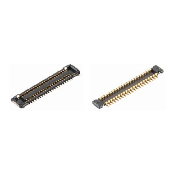
- Page 1 Narrow-pitch Connectors onnector A35US Operation manual ACCTF14E-3 2015.09 industrial.panasonic.com/ac/e/...
- Page 2 Operation manual for Narrow-pitch connectors A35US Contents 01.Introduction ..................... 2 02.Precautions for product design ............... 3 03.Precautions for mounting and reflow soldering ........15 04.Precautions for mating and unmating ........... 25 Points which particularly need to be confirmed before designing products are bold and underlined.
-
Page 3: Introduction
Operation manual for Narrow-pitch connectors A35US 01. Introduction Our Advanced series A35US consists of ultra-small connectors with a terminal pitch of 0.35 mm, a stacking height of 0.6mm, and a shorthand width of 2.2 mm. This connector is designed for board-to-FPC connections that require a more space-saving connector than our A35S Series. -
Page 4: Precautions For Product Design
Operation manual for Narrow-pitch connectors A35US 02. Precautions for product design 02-1. Considerations in mechanical design 1) Position of the connector on a board Rigid boards tend to warp in a direction perpendicular to the rolling direction during the production process. Poor soldering may occur depending on the warping direction. - Page 5 Operation manual for Narrow-pitch connectors A35US 3) Prevention of problems during use (1)The connectors have a simple locking structure, but make sure to consider preventive measures against the detachment of mated connectors during practical use. Cushioning material Casing Reinforcing plate...
- Page 6 Operation manual for Narrow-pitch connectors A35US (3)To facilitate the mating of connectors, we recommend that you pay attention to the following points when designing the motherboard. - Provide a reference mark. - Design a layout that allows easy-checking of the connector mating condition.
- Page 7 Operation manual for Narrow-pitch connectors A35US 02-2. Precautions for board design 1) Circuit design (1)When designing the terminal foot pattern, check the latest specifications and examine the recommended foot pattern and dimensions of the metal mask opening. The current recommendations are indicated on pages 13 and 14.
- Page 8 Operation manual for Narrow-pitch connectors A35US (4)Pay attention to the following point as a pattern peeling preventive measure when removing the connector. - Make the foot pattern length longer than the coverlay opening. In general, at least 0.3 mm. (5)Foot pattern dimensions indicated in the drawings are intended to achieve the minimum area on the premise that the reflow-soldering process is used.
- Page 9 Operation manual for Narrow-pitch connectors A35US (7)Resist between pins When it is needed to provide resist between the pins, there is a way to adopt the overresist method as below. (If the resist is out of alignment, the pattern width 0.20mm would not change.)
- Page 10 Operation manual for Narrow-pitch connectors A35US 2) FPC board design (1)Positions of connectors on the FPC The FPC board is made by laminating a polyimide layer, copper foil, and adhesive layers. Since each material has slightly different heat-shrinkable properties, warpage may occur typically due the reflow heat in the following cases. This may cause poor soldering.
- Page 11 Operation manual for Narrow-pitch connectors A35US (2)FPC board specifications Control the thicknesses of the coverlay and adhesive to prevent poor soldering. This connector has no stand-off. Therefore, minimize the thickness of the coverlay, etc. so as to prevent the occurrence of poor soldering.
- Page 12 Operation manual for Narrow-pitch connectors A35US 3) Reinforcing plate design We recommend the use of a reinforcing plate with appropriate thickness and rigidity to prevent solder peeling and pattern peeling when unmating the connector, and to guard against board warpage during the reflow process.
- Page 13 Operation manual for Narrow-pitch connectors A35US Metal Mask Design Since this connector is designed with an ultra low-profile, pay attention to the following precautions for reflow soldering. (1)In addition to the amount of applied solder, the reflow-soldering environment and temperature profile affect the finish quality after reflow soldering. Make sure to adjust the amount of solder applied after checking the finish quality in a test run.
- Page 14 Operation manual for Narrow-pitch connectors A35US Recommended specifications for PC-board and metal mask opening area When designing please verify with the product specification sheets Applicable product:A35US narrow-pitch connector socket (Mated height:0.6mm) Recommended PC-board pattern (Mount-pad layout) Insulation area Recommended metal mask pattern When the metal mask thickness is 100 m...
- Page 15 Operation manual for Narrow-pitch connectors A35US Recommended specifications for PC-board and metal mask opening area Applicable product:A35US narrow-pitch connector header (Mated height:0.6mm) Recommended PC-board pattern (Mount-pad layout) Insulation area Recommended metal mask pattern When the metal mask thickness is 100 m...
-
Page 16: Precautions For Mounting And Reflow Soldering
Operation manual for Narrow-pitch connectors A35US 03. Precautions for mounting and reflow soldering 03-1. Mounting When mounting, a multifunctional mounter is recommended If using a high-speed mounter, controle the suction force by using a multifunctional head 03-2. Points to consider when selecting a pickup nozzle... - Page 17 Operation manual for Narrow-pitch connectors A35US ●Examples of suction nozzle shape ① Elongated hole ② Circular hole Available for less than 50 pins and except for the case of connector turning around when mounted. ●Connector weight (socket) Mated height:0.6mm (Unit;g)...
- Page 18 Operation manual for Narrow-pitch connectors A35US 2) Picking up the header (1)The suction area on the header is 0.8 mm in the shorter direction. If it is difficult to reliably insert the nozzle to the connector bottom face of 0.8 mm widthwise, the header can be picked up by converting the entire top face of the connector as shown below.
- Page 19 Operation manual for Narrow-pitch connectors A35US ●Examples of suction nozzle shape ② Circular hole ① Elongated hole (Unit;mm) Available for less than 50 Pins pins and except for the case of connector turning around when mounted. 10.0 11.5 *It is available to suck the connector’s whole top surface.
- Page 20 Operation manual for Narrow-pitch connectors A35US 03-3. Precautions for reflow soldering (1)Measure the temperature profile at the mounted connector position, and make sure that it conforms to the recommended profile. (2)When the molded part of connector melts or becomes deformed during the reflow process, the heating temperature may be too high, or the connector may be affected by a nearby electronic component with high heat capacity.
- Page 21 Operation manual for Narrow-pitch connectors A35US 03-4. Precautions for manual soldering and solder rework The size of this connector has been reduced in order to achieve a narrow pitch and save space. Therefore, take great care when carrying out manual soldering or rework.
- Page 22 Operation manual for Narrow-pitch connectors A35US 03-5. Detailed precautions for solder rework (1)Flux-applying tool To prevent solder creeping to a contact section, we recommend the use of a brush pen that can apply an appropriate amount of flux. (e.g., BON-102F, Japan Bonkote)
- Page 23 Operation manual for Narrow-pitch connectors A35US 03-6. Detailed precautions for manual soldering (1)General precautions - When applying flux, apply it thinly on each foot pattern using a brush pen as shown on the previous page. (Place the connector at a predetermined position after applying flux.)
- Page 24 Operation manual for Narrow-pitch connectors A35US 03-7. Flux cleaning method of PC board There is no need to clean this product. If cleaning, pay attention to the following points to prevent the negative effect to the product (1)In order to keep the solvent purity and to enhance cleaning, prepare equipments such as boil, ultrasonic cleaning with cold solvent and vapor washing.
- Page 25 Operation manual for Narrow-pitch connectors A35US 03-8. Solder evaluation of 0.35mm pitch connector With the present technique, it is possible to mount the 0.35mm pitch connectors. However, pay attention to the solder printing and the following points when mounting. (*Evaluation product: Our P35S)
-
Page 26: Precautions For Mating And Unmating
Operation manual for Narrow-pitch connectors A35US 04. Precautions for mating and unmating 04-1. Precautions for mating This connector features a compact and thin design. Although it is designed to be easily handled, follow the rules for mating below to avoid damage to the molded part and buckling or deformation of the contact. - Page 27 Operation manual for Narrow-pitch connectors A35US 04-2. Precautions for connector unmating (1)Hold the reinforcing plate at unmating the connector. (2)Lift straight up to unmate. Lift up (3)If the method of unmating described above is not feasible due to a lack of space around the connector, please lift around one of the shorter sides of the connector to unmate it.
- Page 28 Operation manual for Narrow-pitch connectors A35US Amendment history Manual No. Date Changes ACCTF14E-1 Company name and format change October, 2013 ACCTF14E-2 Division name change June, 2015 ACCTF14E-3 Drawing change September, 2015 Panasonic Corporation ACCTF14E-3 201509 © - 27 - Panasonic Corporation 2015...
- Page 29 ACCTF14E-3 201509...