Table of Contents
DCR-TRV725E/TRV730/TRV730E/TRV828/
SERVICE MANUAL
SERVICE MANUAL
Ver 1.0 2001. 03
On the VC-262 board
This service manual provides the information that is premised the
circuit board replacement service and not intended repair inside the
VC-262 board.
Therefore, schematic diagram, printed wiring board, waveforms, parts
list and electrical parts list of the VC-262 board are not shown.
The following pages are not shown.
Printed wiring board ......................... Pages 4-11 to 4-14
Schematic diagram .......................... Pages 4-15 to 4-58
Waveforms and parts list ................. Pages 4-101 to 4-104
Electrical parts list ............................ Pages 6-19 to 6-31
Video camera
recorder
System
Video recording system
2 rotary heads
Helical scaning system
Audio recording system
Rotary heads, PCM system
Quantization: 12 bits (Fs 32 kHz,
stereo 1, stereo 2), 16 bits
(Fs 48 kHz, stereo)
Video signal
DCR-TRV730/TRV828/TRV830:
NTSC color, EIA standards
DCR-TRV725E/TRV730E/TRV828E/
TRV830E:
PAL colour, CCIR standards
Recommended cassette
Hi8/Digital8 video cassette
Recording/playback time
DCR-TRV730/TRV828/TRV830:
(using 120 min. Hi8 video cassette)
DCR-TRV725E/TRV730E/TRV828E/
TRV830E:
(using 90 min. Hi8 video cassette)
SP mode: 1 hour
LP mode: 1 hour and 30 minuites
TRV828E/TRV830/TRV830E
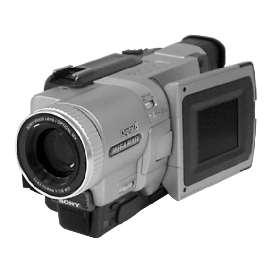
Photo : DCR-TRV730E
RMT-814
SPECIFICATIONS
Fastforward/rewind time
DCR-TRV730/TRV828/TRV830:
(using 120 min. Hi8 video cassette)
DCR-TRV725E/TRV730E/TRV828E/
TRV830E:
(using 90 min. Hi8 video cassette)
Approx. 5 min.
Viewfinder
Electric Viewfinder, Monochrome
Image device
4.5 mm (1/4 type CCD)
(Charge Coupled Device)
Approx. 1 070 000 pixels
(Memory mode: 1 000 000 pixels)
(Camera mode: 690 000 pixels)
Lens
Combined power zoom lens
Filter diameter 37 mm (1 1/2 in.)
18× (Optical), 500× (Digital)
Focal length
4.1 – 73.8 mm (3/16 – 3 in.)
When converted to a 35 mm still
camera
DIGITAL VIDEO CAMERA RECORDER
Hong Kong Model
DCR-TRV730/TRV730E/TRV828/
For MECHANISM ADJUSTMENT, refer to the
"8mm Video MECHANICAL ADJUSTMENT
IX
MANUAL
M2000 MECHANISM " (9-929-861-
11).
NTSC model : DCR-TRV730/TRV828/TRV830
PAL model
: DCR-TRV725E/TRV730E/
TRV828E/TRV830E
Camera mode:
47 – 846 mm (1 7/8 – 33 3/8 in.)
Memory mode:
39 - 702 mm (1 9/16 – 27 3/4 in.)
Colour temperature
Auto
Minimum illumination
7 lx (lux) (F 1.8)
0 lx (lux) (in the NightShot mode)*
* Objects unable to be seen due to
the dark can be shot with infrared
lighting.
Input/output
connectors
S video input/output
4-pin mini DIN
Luminance signal: 1 Vp-p,
75 Ω (ohms), unbalanced
Chrominance signal:
DCR-TRV730/TRV828/TRV830:
Ω (ohms), unbalanced
0.286 Vp-p, 75
DCR-TRV725E/TRV730E/TRV828E/
TRV830E:
Ω (ohms), unbalanced
0.3 Vp-p, 75
RMT-814
US Model
Canadian Model
Korea Model
DCR-TRV730/TRV828/TRV830
AEP Model
UK Model
DCR-TRV725E/TRV730E/
TRV828E/TRV830E
E Model
TRV828E/TRV830/TRV830E
Australian Model
DCR-TRV730E/TRV828E
Chinese Model
DCR-TRV828E
M2000 MECHANISM
Audio/Video input/output
AV MINIJACK, 1 Vp-p, 75 Ω
(ohms), unbalanced, sync negative
327 mV, (at output impedance more
than 47 kΩ (kilohms))
Output impedance with less than
2.2 kΩ (kilohms)/Stereo minijack
(ø 3.5 mm)
Input impedance more than 47 kΩ
(kilohms)
Headphone jack
Stereo minijack (ø 3.5 mm)
USB jack
mini-B
LANC
jack
Stereo mini-minijack (ø 2.5 mm)
MIC jack
Stereo minijack (ø 3.5 mm)
DV input/output
4-pin connector
— Continued on next page —
Table of Contents

Related Manuals for Sony DCR-TRV725E


Summary of Contents for Sony DCR-TRV725E
- Page 1 VC-262 board are not shown. NTSC model : DCR-TRV730/TRV828/TRV830 The following pages are not shown. PAL model : DCR-TRV725E/TRV730E/ Printed wiring board ......Pages 4-11 to 4-14 TRV828E/TRV830E Schematic diagram ......Pages 4-15 to 4-58 Waveforms and parts list ....
- Page 2 MARK 0 ON THE SCHEMATIC DIAGRAMS AND IN THE PARTS CRITIQUES POUR LA SÉCURITÉ DE FONCTIONNEMENT. NE LIST ARE CRITICAL TO SAFE OPERATION. REPLACE THESE REMPLACER CES COMPOSANTS QUE PAR DES PIÈSES SONY COMPONENTS WITH SONY PARTS WHOSE PART NUMBERS DONT LES NUMÉROS SONT DONNÉS DANS CE MANUEL OU APPEAR AS SHOWN IN THIS MANUAL OR IN SUPPLEMENTS DANS LES SUPPÉMENTS PUBLIÉS PAR SONY.
- Page 3 — 3 —...
- Page 4 TABLE OF CONTENTS SERVICE NOTE Recording still images on “Memory Stick” – Memory Photo recording ·············································· 1-30 POWER SUPPLY DURING REPAIRS ····························· 8 Recording an image from a tape as a still image ················· 1-32 TO TAKE OUT A CASSETTE WHEN NOT EJECT Recording moving pictures on “Memory Stick”s (FORCE EJECT) ································································...
- Page 5 • PD-139 (RGB DRIVE, TIMING GENERATOR, LCD 3-9. POWER BLOCK DIAGRAM (3/3) ······························ 3-17 DRIVE, BACK LIGHT DRIVE) PRINTED WIRING BOARD PRINTED WIRING BOARDS AND (DCR-TRV725E/TRV730E/TRV828/TRV828E/ TRV830/TRV830E) ······································ 4-89 SCHEMATIC DIAGRAMS • PD-139 (RGB DRIVE, TIMING GENERATOR)(1/2) 4-1. FRAME SCHEMATIC DIAGRAM (1/3) ······················· 4-1 SCHEMATIC DIAGRAM ····························...
- Page 6 TRV830E) ····································································· 5-32 IR Audio Deviation Check (VC-262 board) ·················· 5-56 Black Limit Adjustment (PD-139 board) 3-6. AUDIO SYSTEM ADJUSTMENTS ···························· 5-57 (DCR-TRV725E/TRV730E/TRV828/TRV828E/ TRV830/ Hi8/Standard8 AFM BPF fo Adjustment (VC-262 board) · 5-57 TRV830E) ····································································· 5-33 Hi8/Standard8 AFM 1.5 MHz Deviation Adjustment Contrast Adjustment (PD-138 board)(DCR-TRV730) ··...
- Page 7 6-1-9. MECHANICAL CHASSIS BLOCK ASSEMBLY-1 ······ 6-9 6-1-10. MECHANICAL CHASSIS BLOCK ASSEMBLY-2 ·· 6-10 6-2. ELECTRICAL PARTS LIST ········································ 6-11 Parts list of the VC-262 board are not shown. Pages from 6-19 to 6-31 are not shown. * Color reproduction frame are shown on pages 243. —...
- Page 8 SERVICE NOTE POWER SUPPLY DURING REPAIRS In this unit, about 10 seconds after power is supplied (8.4V) to the battery terminal using the service power code (J-6082-223-A), the power is shut off so that the unit cannot operate. These following two methods are available to prevent this. Take note of which to use during repairs. Method 1.
- Page 9 SELF-DIAGNOSIS FUNCTION Self-diagnosis Function Self-diagnosis Display When problems occur while the unit is operating, the self-diagnosis When problems occur while the unit is operating, the counter of the function starts working, and displays on the viewfinder or Display viewfinder or Display window shows a 4-digit display consisting window what to do.
- Page 10 Self-diagnosis Code Table Self-diagnosis Code Block Detailed Symptom/State Correction Function Code Non-standard battery is used. Use the InfoLITHIUM battery. Condensation. Remove the cassette, and insert it again after one hour. Video head is dirty. Clean with the optional cleaning cassette. LOAD direction.
- Page 11 Self-diagnosis Code Block Detailed Symptom/State Correction Function Code Inspect the lens block focus reset sensor (Pin ql of CN1121 of Difficult to adjust focus VC-262 board) when focusing is performed when the control dial (Cannot initialize focus.) is rotated in the focus manual mode and the focus motor drive circuit (IC1554 of VC-262 board) when the focusing is not performed.
- Page 12 DCR-TRV725E/TRV730/TRV730E/TRV828/ TRV828E/TRV830/TRV830E SECTION 1 This section is extracted from instruction GENERAL manual. (DCR-TRV725E/TRV730E/ TRV828E/TRV830E) Checking supplied Проверка прилагаемых English accessories принадлежностей Main Features Make sure that the following accessories are Убедитесь, что следующие принадлежности Taking moving or still images, and playing them back supplied with your camcorder.
- Page 13 — Подготовка к эксплуатации — Использование данного Использование — Getting started — Using this manual руководства Using this manual данного руководства Before using your camcorder Перед началом эксплуатации The instructions in this manual are for the four В данном руководстве по эксплуатации Вашей...
- Page 14 “InfoLITHIUM” (серии M). Ваша видеокамера Непрерывная* Типичная** Непрерывная* Типичная** работает только с батарейным блоком series battery packs have the mark. “InfoLITHIUM” is a trademark of Sony “InfoLITHIUM”. На батарейных блоках серии SERIES NP-FM50 Corporation. “InfoLITHIUM” М имеется знак (прилагается) (supplied)/ SERIES “InfoLITHIUM”...
- Page 15 IN, даже если провод электропитания и не сократится приблизительно на 20 %. подсоединен к сетевой розетке. Using a car battery Use Sony DC Adaptor/Charger (optional). Использование автомобильного аккумулятора Используйте адаптер/зарядное устройство постоянного тока фирмы Sony (приобретается...
- Page 16 •The cassette compartment may not be closed помехи мозаичного типа (включая другие (5) After the cassette compartment going down полностью опустится, закройте крышку, видеокамеры DCR-TRV725E/TRV730E/ when you press any part of the lid other than completely, close the lid until it clicks. чтобы она щелкнула.
- Page 17 Код времени (только для лент, записанных в цифровой системе Digital8 (hours:minutes:seconds:frames) in VCR or Код времени указывает время записи или PLAYER (DCR-TRV725E only) mode. You воспроизведения, “0:00:00” (часы: минуты: cannot rewrite only the time code. секунды) в режиме CAMERA и “0:00:00:00”...
- Page 18 Recording a picture Запись изображения Recording a picture Запись изображения Shooting backlit subjects Съемка объектов с задней Shooting in the dark Съемка в темноте – BACK LIGHT подсветкой – BACK LIGHT – NightShot/Super NightShot – Ночная съемка/Ночная суперсъемка When you shoot a subject with the light source Если...
- Page 19 (2) Set the POWER switch to VCR or PLAYER be played back for a few seconds, and then your секунд записанной части, а затем (DCR-TRV725E only) while pressing the small (1) Установите источник питания и вставьте camcorder will return to the standby mode. You видеокамера...
- Page 20 положение VCR или PLAYER (только модель Для покадрового просмотра playback in the reverse direction, press c. To Press X during playback. To resume playback, DCR-TRV725E). воспроизведения изображения resume normal playback, press N. press X or N. Нажмите кнопку C на пульте дистанционного...
- Page 21 высвечивается кнопка SUPER LASER LINK) Ваша видеокамера потребляет питание. SUPER LASER LINK is a trademark of Sony Corporation. Нажмите кнопку SUPER LASER LINK для выключения функции лазерного суперканала передачи сигналов, если она не требуется.
- Page 22 – The POWER switch is set to OFF (CHG), VCR – Переключатель POWER установлен в изображения на ленты с помощью таймера or PLAYER (DCR-TRV725E only). положение OFF (CHG), VCR или PLAYER самозапуска. Для этой операции Вы также (1) In the standby mode, press MENU to display (только...
- Page 23 Использование Использование Using the wide mode широкоэкранного режима Using the fader function функции фейдера You can record a 16:9 wide picture to watch on Вы можете записывать широкоформатное You can fade the picture in or out to give your Вы можете выполнять плавное введение и the 16:9 wide-screen TV (16:9WIDE).
- Page 24 Использование Using special effects Использование специальных Using special effects специальных эффектов – Picture effect эффектов – Эффект изображения – Picture effect – Эффект изображения (1) Press MENU to display the menu settings in (1) Нажмите кнопку MENU для отображения CAMERA mode. установок...
- Page 25 Using the PROGRAM Использование Using special effects Использование специальных AE function функции PROGRAM AE – Digital effect эффектов – Цифровой эффект To cancel the digital effect Для отмены цифрового эффекта You can select PROGRAM AE (Auto Exposure) Вы можете выбрать режим PROGRAM AE mode to suit your specific shooting requirements.
- Page 26 Adjusting the Регулировка Focusing manually exposure manually экспозиции вручную Фокусировка вручную You can manually adjust and set the exposure. Вы можете отрегулировать и установить You can gain better results by manually adjusting Вы можете получить лучшие результаты путем Adjust the exposure manually in the following экспозицию...
- Page 27 CAMERA again, then proceed from step 1. видеокамере We recommend setting the POWER switch to Питание выключится автоматически. VCR or PLAYER (DCR-TRV725E only) or Символы, которые Вы ввели, сохранятся в (1) While your camcorder is in the standby mode, (1) В режиме ожидания видеокамеры, removing the cassette so that your camcorder памяти...
- Page 28 Playing back a tape Воспроизведение ленты — Advanced Playback Operations — — Усовершенствованные операции воспроизведения — Playing back a tape Воспроизведение ленты с with digital effects с цифровыми эффектами with picture effects эффектами изображения During playback, you can process a scene using Во...
- Page 29 неправильно. (1) Set the POWER switch to VCR or PLAYER (1) Установите переключатель POWER в положение VCR или PLAYER (только (DCR-TRV725E only). модели DCR-TRV725E). (2) Press SEARCH MODE on the Remote (2) Нажимайте повторно кнопку SEARCH Commander repeatedly, until the date search MODE на...
- Page 30 (1) Set the POWER switch to VCR or PLAYER (1) Установите переключатель POWER в recorded on tape (photo search). изображения записанного на ленту (DCR-TRV725E only). положение VCR или PLAYER (только You can also search for still images one after (фотопоиск).
- Page 31 (соединительного кабеля цифрового (3)Set the POWER switch to VCR or PLAYER КВМ и вставьте записанную ленту в Вашу – Picture effect видеосигнала DV). (DCR-TRV725E only). видеокамеру. – Digital effect Более подробные сведения относительно (4) Play back the recorded tape on your (2) Установите...
- Page 32 The IR SETUP code is stored in the memory of Код IR SETUP хранится в памяти Вашей Вашей видеокамере в положение VCR или (DCR-TRV725E only) on your camcorder. your camcorder. Be sure to set the correct code видеокамеры. Убедитесь, что Вы выбрали...
- Page 33 (1) Установите переключатель POWER на Вашей видеокамере в положение VCR (DCR-TRV725E only) on your camcorder. (DCR-TRV725E only) on your camcorder . Вашей видеокамере в положение VCR или или PLAYER (только модель DCR- (2) Insert a blank tape (or a tape you want to (2) Turn the power of the connected VCR on, PLAYER (только...
- Page 34 Dubbing only desired scenes Перезапись только нужных эпизодов Dubbing only desired scenes Перезапись только нужных эпизодов – Digital program editing – Цифровой монтаж программы – Digital program editing – Цифровой монтаж программы Erasing the programme you have set Стирание программы, которую Вы Operation 2: Performing Digital Действие...
- Page 35 Recording video or TV Запись видео или Запись видео или телевизионных programmes телевизионных программ Recording video or TV programmes программ – DCR-TRV730E/TRV828E/TRV830E – Только модели DCR-TRV730E/ When you have finished dubbing a Если Вы закончили перезапись на only TRV828E/TRV830E tape ленту...
- Page 36 модель DCR-TRV725E) или режиме tapes recorded in the Digital8 system. только для лент, записанных в цифровой (1) In CAMERA, VCR, PLAYER (DCR-TRV725E MEMORY, нажмите кнопку MENU. •The picture and sound recorded on the section системе Digital8 (2) Поверните диск SEL/PUSH EXEC для...
- Page 37 VCR SET (DCR-TRV730E/TRV828E/ zoom is performed digitally. (p. 29) TRV830E) TRV830E) 500× To activate digital zoom. More than 18× to 500× PLAYER SET (DCR-TRV725E) PLAYER SET (DCR-TRV725E) zoom is performed digitally. (p. 29) LCD/VF SET LCD/VF SET MEMORY SET 16:9WIDE z OFF —...
- Page 38 Changing the menu settings Changing the menu settings POWER POWER Icon/item Mode Meaning switch Icon/item Mode Meaning switch STILL SET SLIDE SHOW — To play back images in a continuous loop MEMORY (p. 175) PIC MODE z SINGLE Not to record continuously MEMORY DELETE ALL —...
- Page 39 • При переноске или хранении “Memory Stick” “Memory Stick”s formatted by Windows OS or •Macintosh and Mac OS, QuickTime are фирменными знаками Sony Corporation. положите ее в футляр. Macintosh computers do not have a guaranteed trademarks of Apple Computer, Inc.
- Page 40 показано на рисунке. (1) Set the POWER switch to VCR, PLAYER является SUPER FINE. (DCR-TRV725E only) or MEMORY. Make sure that the LOCK is set to the left (unlock) (1) Установите переключатель POWER в position. положение VCR, PLAYER (только модели...
- Page 41 Using “Memory Stick” Использование “Memory Stick” Using “Memory Stick” Использование “Memory Stick” – introduction –Введение – introduction –Введение Image size settings Установки размера изображения MEMOR Y S E T Setting/Установка Meaning/Значение Indicator/Индикатор S T I L L S E T MO V I E S E T P R I N T MA R K Recording/Запись...
- Page 42 Recording still images on Запиcь неподвижных изображений Recording still images on Запиcь неподвижных изображений “Memory Stick” на “Memory Stick” – Фотоcъемка с “Memory Stick” на “Memory Stick” – Фотоcъемка с сохранением в памяти сохранением в памяти – Memory Photo recording –...
- Page 43 самозапуска с помощью пульта дистанционного управления. PLAY – Self-timer recording is finished. – The POWER switch is set to OFF (CHG), VCR or PLAYER (DCR-TRV725E only). Примечание Режим записи по таймеру самозапуска будет To check the image to be recorded автоматически отменен, если: You can check the image with pressing PHOTO –...
- Page 44 (1) Установите переключатель POWER в видео для ввода сигналов изображения с external unit used to play back the image. положение VCR или PLAYER (только модель (DCR-TRV725E only). внешнего устройства, используемого для DCR-TRV725E). (2) Press N. The picture recorded on the tape is The picture may be recorded on the “Memory...
- Page 45 Наложение неподвижного Superimposing a still image изображения из “Memory Recording moving pictures from Запись движущихся изображений in the “Memory Stick” on a tape с ленты Stick” на подвижное an image – MEMORY MIX изображение – MEMORY MIX If your TV or VCR has an S video jack Если...
- Page 46 Superimposing a still image in Наложение неподвижного изображения Superimposing a still image in Наложение неподвижного изображения the “Memory Stick” on an image из “Memory Stick” на подвижное the “Memory Stick” on an image из “Memory Stick” на подвижное изображение – MEMORY MIX изображение...
- Page 47 Вставьте “Memory Stick” в Вашу видеокамеру. Примечания о названии файла •The directory is not displayed if the structure of PLAYER (DCR-TRV725E only). Make sure •Каталог не отображается, если структура the directory does not conform to the DCF98 that the LOCK is set to the left (unlock) (1) Установите...
- Page 48 помощью другой аппаратуры (1) Set the POWER switch to MEMORY, VCR or Эти файлы могут не отображаться на PLAYER (DCR-TRV725E only). Make sure (1) Установите переключатель POWER в индексном экране. that the LOCK switch is set to the left (unlock) положение...
- Page 49 OK. (потяните и отпустите). Still image/Неподвижное “Dcim” folder t “100msdcf” folder t Image file • Sony Camcorder USB Driver (7) Restart your computer. изображение Папка “Dcim” t Папка “100msdct” t Файл изображения • Sony Camcorder USB Shim Moving picture*/Движущееся...
- Page 50 Просмотр изображений с использованием Просмотр изображений с использованием Viewing images using your Viewing images using your персонального компьютера персонального компьютера computer computer Software Программы Unplug the USB cable/Eject the Отсоединение кабеля USB/ •Depending on your application software, the •В зависимости от прикладной программы, “Memory Stick”...
- Page 51 (1) Set the POWER switch to MEMORY, VCR or (только модели DCR-TRV725E). В режиме PB ZOOM The digital effect function does not work. PLAYER (DCR-TRV725E only). Make sure Убедитесь, что переключатель LOCK Функция цифрового эффекта не работает. that the LOCK is set to the left (unlock) установлен...
- Page 52 (1) Set the POWER switch to MEMORY, VCR or (1) Установите переключатель POWER в содержание “Memory Stick” перед положение MEMORY, VCR или PLAYER before formatting. PLAYER (DCR-TRV725E only). Make sure форматированием. (только модели DCR-TRV725E). that the LOCK is set to the left (unlock) Убедитесь, что фиксатор LOCK If the write-protect tab on the “Memory Stick”...
- Page 53 (1) Set the POWER switch to MEMORY, VCR or is set to LOCK Если лепесток защиты записи на “Memory положение MEMORY, VCR или PLAYER PLAYER (DCR-TRV725E only). Make sure You cannot delete images. Stick” установлен в положение LOCK (только модели DCR-TRV725E). Убедитесь, that the LOCK is set to the left (unlock) что...
- Page 54 An unknown picture is displayed on CAMERA or DEMO MODE is set to ON in the menu problem. If the problem persists, disconnect the power source and contact your Sony dealer or the screen. settings without a cassette inserted, your camcorder local authorized Sony service facility.
- Page 55 C:22:ss • DISPLAY is set to V-OUT/LCD in the menu settings. The picture from a TV or VCR does c Clean the heads using the Sony V8-25CLD cleaning not appear even when your c Set it to LCD. (p. 107) camcorder is connected to outputs on cassette (optional).
- Page 56 стандартной ленты 8 на других КВМ tape on other VCRs (including other DCR- You cannot record software on your camcorder (Только модели DCR-TRV730E/TRV828E/ (включая другие аппараты DCR-TRV725E/ TRV725E/TRV730E/TRV828E/TRV830E). that contains copyright control signals for TRV830E) TRV730E/TRV828E/TRV830E) могут copyright protection of software.
- Page 57 съемки без вставленной кассеты, пока не reached the end of its life. Please buy a new кабеля i.LINK (цифрового кабеля DV). При transport bus proposed by SONY, and is a выключится питание. battery pack. подсоединении данного аппарата к с двумя...
- Page 58 принадлежности, рекомендуемые в данной • При записи с помощью шнура i.LINK, checked by a Sony dealer before operating it изображение можно обрабатывать и инструкции по эксплуатации. Connection to your computer any further.
- Page 59 If any problem occurs, unplug your camcorder – Если на поверхности линзы остались отпечатки пальцев and contact your nearest Sony dealer. Если произошла утечка внутреннего – В жарких или влажных местах To prevent mold from occurring, periodically вещества...
- Page 60 Обозначение частей и Обозначение частей и Identifying the parts and controls Identifying the parts and controls регуляторов регуляторов eg Intelligent accessory shoe eg Держатель для установки принадлежностей wg EDITSEARCH buttons (p. 37) wg Кнопка EDITSEARCH (стр. 37) eh END SEARCH button (p. 37) eh Кнопка...
- Page 61 Режимы пульта дистанционного управления /Mirror mode indicator (p. 28) индикатор зеркального режима (стр. 28) Sony VCR in the Commander mode VTR 2, we 1, 2 и 3 используются для отличия данной 2 Индикатор формата (стр. 201) recommend changing the Commander mode or видеокамеры...
- Page 62 Обозначение частей и Identifying the parts and controls регуляторов qf STBY/REC indicator (p. 26)/Video control qf Индикатор STBY/REC (стр. 26)/режим mode (p. 42)/Image size indicator (p. 132)/ видеоконтроля (стр. 42)/индикатор Image quality mode indicator (p. 130) размера изображения (стр. 132)/ индикатор...
- Page 63 2-13. VC-262 board 2-14. Mechanism deck-2, MD frame (M) [CONNECTION DIAGRAM FOR SERVICE POSITION (Mainly for voltage measurement and check)] (VC-262, FU-155, CD-329, SI-030, MM-043, CF-084 boards, Mechanism deck-2) 2.5 inch LCD model : DCR-TRV725E/TRV730/TRV730E 3.5 inch LCD model : DCR-TRV828/TRV828E/TRV830/TRV830E...
- Page 64 NOTE: Follow the disassembly procedure in the numerical order given. 2-1. LCD UNIT, PD-138/139 BOARD (2.5 INCH LCD MODEL) (TRV725E/TRV730/TRV730E) REMOVING THE BACK LIGHT P cabinet C (M) assembly screws (M2 × 4) (H) Remove the indication LCD (M) block assembly, Two screws back light in the direction of the arrow C .
- Page 65 2-2. LCD UNIT, PD-139 BOARD (3.5 INCH LCD MODEL) (TRV828/TRV828E/TRV830/TRV830E) REMOVING THE BACK LIGHT screws P cabinet C (M) assembly (M2 × 4) (H) Remove the indication LCD (M) block assembly, Two screws back light in the direction of the arrow C . (M1.7 ×...
- Page 66 2-3. FRONT PANEL SECTION, SI-030 BOARD Open the cassette 4 Two MI screws lid. (M2 × 4) (H) REMOVING THE SI-030 BOARD Claw Remove the FP-273 board in the 1 Cushion (SI) direction of the arrow B . i t a D i g 3 MI screw...
- Page 67 2-4. CABINET (R) SECTION screws (M2 × 4) (H) 1 MI screw Three claws (M2 × 4) (H) 4 MI screw (M2 × 4) (H) 3 Cabinet 6 MI screw (upper) (M2 × 4) (H) Two tapping screws Harness (M1.7 × 5) (VP-076) (20P) Flexible flat cable (FFC-001) (45P)
- Page 68 2-6. CF-084 BOARD Cabinet (R) block assembly Two claws CF-084 board, Flexible flat cable (FFC-001) - 0 8 a r d Two tapping screws (B2 × 5) [CF-084, SI-030 BOARDS SERVICE POSITION] CPC-13 jig CN1108 Claw (J-6082-443-A) CN1108 CPC lid (BT) 1 MI screw (M2 ×...
- Page 69 2-7. EVF SECTION, LB-071 BOARD PRECAUTION WHEN ATTACHING FP-268 FLEXIBLE BOARD 1 FP-268 flexible board (20P) 3 EVF section FP-268 flexible board Flexible - 0 8 2 Three tapping a r d guide screws (B2 × 5) EVF section Fix the FP-268 flexible board to both the EVF section, and flexible guide with the both-sided adhesive tape.
- Page 70 2-8. LENS SECTION, CD-329 BOARD 7 Screw 8 Screw (M1.7 × 2.5), p (M1.7 × 2.5), p 3 Ferrite bead TRV725E/TRV730E/ TRV828E/TRV830E 5 FP-317 flexible board (24P) REMOVING THE STEPPING MOTORS 2 Two tapping screws (M1.7 × 5) 4 Tape (B) 0 Two tapping screws 1 Remove the four solderings...
- Page 71 2-9. MM-043 BOARD 5 MM-043 board REMOVING THE FP-319 FLEXIBLE BOARD - 2 6 a r d MS holder (M) - 0 4 1 Tape A FP-319 flexible a r d 2 Two claws board Memory stick connector 6 Remove the two Three screws solderings...
- Page 72 2-10.BATTERY PANEL SECTION, BATTERY TERMINAL BOARD 3 MI screw 4 Claw Remove the battery panel section 2 MI screw (M2 × 4) (H) (M2 × 4) (H) in the direction of the arrow A . Tapping screw (M1.7 × 5) - 2 6 a r d 7 MI...
- Page 73 2-12.CABINET (L) SECTION, MECHANISM DECK-1 Four dowels Screw (M1.7 × 2.5), p REMOVING THE CS FRAME ASSEMBLY (M) Cabinet (L) section, CS frame assembly (M) Cabinet (L) 2 Two MI screws (M2 × 4) (H) assembly 1 MI screw (M2 × 4) (H) - 2 6 a r d 4 Grip...
- Page 74 2-13.VC-262 BOARD Remove the VC-262 board Remove the flexible boards in the direction of the arrow H . Two screws Screw (M1.7 × 2.5), p (M1.7 × 2.5), p 3 VC sheet - 2 6 a r d FP-264 flexible Two screws (M1.7 ×...
- Page 75 [CONNECTION DIAGRAM FOR SERVICE POSITION (Mainly for voltage measurement and check)] (VC-262, FU-155, CD-329, SI-030, MM-043, CF-084 BOARDS, MECHANISM DECK-2) Note: Operate the VTR using the adjustment remote commander (with the HOLD switch set in the OFF position) Battery panel section AC POWER AC IN...
- Page 76 2-15.HINGE SECTION REMOVING THE HINGE ASSEMBLY Remove the Harness (VP-076) (6, 20P) in the direction of the arrow Harness (VP-076) (6, 20P) Then bend the harness so that it is laid along with the connector. 2 FP-283 board (6P) Two claws Hinge Hinge cover C (M) assembly...
- Page 77 2-16.CIRCUIT BOARDS LOCATION LB-071 (EVF BACK LIGHT) CF-084 CD-329 (EVF DRIVE, USER FUNCTION) (CCD IMAGER) PD-138 (TRV730) PD-139 TRV725E/TRV730E/TRV828/ TRV828E/TRV830/TRV830E RGB DRIVE, TIMING GENERATOR, LCD DRIVE, BACK LIGHT DRIVE FU-155 (POWER SUPPLY) MM-043 (MEMORY) FP-318 (SWITCH) FP-273 (MIC, HEADPHONES) FP-272 (LANC, DV IN/OUT) FP-270 FP-332...
- Page 78 2-17.FLEXIBLE BOARDS LOCATION The flexible boards contained in the mechanism deck and that in the zoom lens are not shown. FP-268 FP-264 FP-319 (MEMORY STICK CONNECTOR) FP-317 FP-342 FP-316 CONTROL SWITCH BLOCK (SS-1380) CONTROL SWITCH BLOCK (SE-1380) FFC-001 2-16E...
- Page 79 DCR-TRV725E/TRV730/TRV730E/TRV828/ SECTION 3 TRV828E/TRV830/TRV830E BLOCK DIAGRAMS 3-1. OVERALL BLOCK DIAGRAM (1/6) ( ) : Page No. shown in ( ) indicates the page to refer on the schematic diagram. CD-329 BOARD VC-262 BOARD(1/5) LENS ASSY (4-10) (4-10) SPCK1 IC1600 (4-17)
- Page 80 DCR-TRV725E/TRV730/TRV730E/TRV828/ TRV828E/TRV830/TRV830E 3-2. OVERALL BLOCK DIAGRAM (2/6) ( ) : Page No. shown in ( ) indicates the page to refer on the schematic diagram. FP-273(2/2) SI-030 VC-262 BOARD(2/5) J301 (FLEXIBLE) BOARD(2/2) (SEE PAGE 4-81) (HEADPHONES) CN301 J302 VSP SO,XVSP SCK...
- Page 81 DCR-TRV725E/TRV730/TRV730E/TRV828/ TRV828E/TRV830/TRV830E 3-3. OVERALL BLOCK DIAGRAM (3/6) ( ) : Page No. shown in ( ) indicates the page to refer on the schematic diagram. FP-272 (1/2) VC-262 BOARD(3/5) (4-29) (FLEXIBLE) X3301 IC3301 24.576MHz (CAIN) CN1114 (4-31) TPA+,- DV SIGNAL...
- Page 82 DCR-TRV725E/TRV730/TRV730E/TRV828/ TRV828E/TRV830/TRV830E 3-4. OVERALL BLOCK DIAGRAM (4/6) ( ) : Page No. shown in ( ) indicates the page to refer on the schematic diagram. M2000 MECHA DECK VC-262 BOARD(4/5) (4-48) (SEE PAGE 4-60) (4-43) (4-48) M901 IC4401 IC1301 CN4402...
- Page 83 DCR-TRV725E/TRV730/TRV730E/TRV828/ TRV828E/TRV830/TRV830E 3-5. OVERALL BLOCK DIAGRAM (5/6) ( ) : Page No. shown in ( ) indicates the page to refer on the schematic diagram. CF-084 BOARD(2/2) VC-262 BOARD(5/5) (4-42) CN1101 IC4803 LANC SIG INTELLIGENT HI CONTROL SHOE/PRT UNREG ACCESSORY...
- Page 84 DCR-TRV725E/TRV730/TRV730E/TRV828/ TRV828E/TRV830/TRV830E 3-6. OVERALL BLOCK DIAGRAM (6/6) ( ) : Page No. shown in ( ) indicates the page to refer on the schematic diagram. LCD TYPE SH MODEL DCR-TRV730 LCD TYPE SO MODEL DCR-TRV725E/TRV730E/TRV828/TRV828E/TRV830/TRV830E (LCD TYPE SH MODEL) HD OUT...
- Page 85 DCR-TRV725E/TRV730/TRV730E/TRV828/ TRV828E/TRV830/TRV830E 3-7. POWER BLOCK DIAGRAM (1/3) ( ) : Page No. shown in ( ) indicates the page to refer on the schematic diagram. CN1113 FU-155 BOARD(1/2) Q405,408-412 F405 PRT HEAD UNREG VC-262 BOARD(1/3) INTELLIGENT ACCESSORY F406 BL CONT...
- Page 86 DCR-TRV725E/TRV730/TRV730E/TRV828/ TRV828E/TRV830/TRV830E 3-8. POWER BLOCK DIAGRAM (2/3) ( ) : Page No. shown in ( ) indicates the page to refer on the schematic diagram. CONTROL SWITCH BLOCK FU-155 BOARD(2/2) VC-262 BOARD(2/3) (SS-1380) (SEE PAGE 4-97) BATT LI3V POWER IC4803...
- Page 87 DCR-TRV725E/TRV730/TRV730E/TRV828/ TRV828E/TRV830/TRV830E 3-9. POWER BLOCK DIAGRAM (3/3) ( ) : Page No. shown in ( ) indicates the page to refer on the schematic diagram. (4-28) VC-262 BOARD(3/3) MM-043 BOARD FP-319 (FLEXIBLE) IC5006 PD-138/139 PD-139 BOARD LCD901 (SEE PAGE (LCD TYPE SO)
- Page 88 DCR-TRV725E/TRV730/TRV730E/TRV828/ SECTION 4 TRV828E/TRV830/TRV830E PRINTED WIRING BOARDS AND SCHEMATIC DIAGRAMS 4-1. FRAME SCHEMATIC DIAGRAM (1/3) INTELLIGENT CD-329 BOARD ACCESSORY SHOE LENS UNIT IMAGER FP-332 FLEXIBLE FP-264 FLEXIBLE FP-317 FLEXIBLE VC-262 BOARD(1/3) CN1108 1/22 CAMERA A/D CONV.,TIMING GENERATOR 12/22 HI8/STD8 PB PROCESS...
- Page 89 DCR-TRV725E/TRV730/TRV730E/TRV828/ TRV828E/TRV830/TRV830E FRAME SCHEMATIC DIAGRAM (2/3) FP-315 FLEXIBLE S401-404,S407,409 CONTROL SWITCH BLOCK(SE-1380) S405/ FP-318 D401 STOP /SUPER NIGHT SHOT/ S103/S102 PAUSE/ FLEXIBLE REW/ PLAY S101 S501 S406,408 SP901 EXPOSURE SPEAKER FOCUS (PANEL OPEN/CLOSE) REC/ AUTO→MANUAL SUPER LASER LINK SEL/PUSH EXEC...
- Page 90 DCR-TRV725E/TRV730/TRV730E/TRV828/ TRV828E/TRV830/TRV830E FRAME SCHEMATIC DIAGRAM (3/3) CONTROL SWITCH BLOCK(SS-1380) CN402 FU-155 BOARD XVTR_MODE_SW S002 REG_GND START/STOP XPHOTO_STBY_SW S003 XCAM_MODE_SW OPEN/EJECT XS/S_SW REG_GND S004 KEY_AD1 PHOTO (PHOTO FREEZE) RV001 XPHOTO_FREEZE ZOOM REG_GND MM-043 BOARD D_2.8V S001 ZOOM_VR POWER CN7302 S_GND XEJECT_SW...
- Page 91 DCR-TRV725E/TRV730/TRV730E/TRV828/ TRV828E/TRV830/TRV830E 4-2. PRINTED WIRING BOARDS AND SCHEMATIC DIAGRAMS THIS NOTE IS COMMON FOR WIRING BOARDS AND SCHEMATIC DIAGRAMS (In addition to this, the necessary note is printed in each block) (For printed wiring boards) (Measuring conditions voltage and waveform) •...
- Page 92 DCR-TRV725E/TRV730/TRV730E/TRV828/ TRV828E/TRV830/TRV830E CD-329 (CCD IMAGER) PRINTED WIRING BOARD For Schematic Diagram — Ref. No. CD-329 Boards; 10,000 Series — • Refer to page 4-99 for waveforms. CD-329 BOARD CCD IMAGER R3401 -REF.NO.:10000 SERIES- XX MARK:NO MOUNT C3404 0.1u NO MARK:REC/PB MODE...
- Page 93 DCR-TRV725E/TRV730/TRV730E/TRV828/ TRV828E/TRV830/TRV830E LS-057 (S/T REEL SENSOR), FP-228 (DEW SENSOR), FP-299 (MODE SWITCH), FP-300 (TAPE TOP), FP-302 (TAPE END), FP-301 (TAPE LED) FLEXIBLE BOARDS FP-302 FP-300 FLEXIBLE (COMPONENT SIDE) LS-057 BOARD FP-300 FLEXIBLE FLEXIBLE Q002 Q001 TAPE END TAPE TOP FP-301...
- Page 94 DCR-TRV725E/TRV730/TRV730E/TRV828/ TRV828E/TRV830/TRV830E FP-332 (USB CONNECTOR), FP-270 (S VIDEO, AUDIO/VIDEO), FP-272 (LANC, DV IN/OUT) FLEXIBLE BOARDS — Ref. No. FP-332, FP-270, FP-272 Flexible Boards; 30,000 Series — FP-270 FLEXIBLE S VIDEO,AV IN/OUT -REF.NO.:20000 SERIES- R101 R102 J101 S VIDEO R108 R109 R111 0.1u...
- Page 95 DCR-TRV725E/TRV730/TRV730E/TRV828/ TRV828E/TRV830/TRV830E MM-043 (MEMORY) PRINTED WIRING BOARD — Ref. No. MM-043 Board; 10,000 Series — For printed wiring boards • Refer to page 4-105 for parts location. • MM-043 board consists of multiple layers. However, only the sides (layers) A and B are shown.
- Page 96 DCR-TRV725E/TRV730/TRV730E/TRV828/ TRV828E/TRV830/TRV830E For Schematic Diagram • Refer to page 4-63 for printed wiring board. MM-043 BOARD MEMORY -REF.NO.:10000 SERIES- XX MARK:NO MOUNT NO MARK:REC/PB MODE CN7301 100P IC7301 REG_GND REG_GND MS_VCC IC7305 IC7304 REG_GND MS_VCC 16MBIT SDRAM MS_BS MS_DIO MS_BS...
- Page 97 DCR-TRV725E/TRV730/TRV730E/TRV828/ TRV828E/TRV830/TRV830E CF-084 (EVF DRIVE, USER FUNCTION) PRINTED WIRING BOARD — Ref. No. CF-084 Board; 10,000 Series — For printed wiring board LB-071 There are a few cases that the part printed on • Refer to page 4-105 for parts location.
- Page 98 DCR-TRV725E/TRV730/TRV730E/TRV828/ TRV828E/TRV830/TRV830E EVF DRIVE, USER FUNCTION 4-69 4-70 CF-084...
- Page 99 CH GND 100k Q101 2SC4116YG-TE85L LINE REC MODEL: DCR-TRV730/TRV730E/TRV828/TRV828E/TRV830/TRV830E LCD_LED_ON LCD B+ ON/OFF R103 TYPE SO MODEL : DCR-TRV730 TYPE SO MODEL TYPE SH MODEL : DCR-TRV725E/TRV730E/TRV828/TRV828E/TRV830/TRV830E R106 R131 PD-138 BOARD(2/2) CN103 CN5704 XCS_LCD_DRIVER XCS_LCD_DRIVER Q102 (THROUGH THE CP-076 HARNESS)
- Page 100 DCR-TRV725E/TRV730/TRV730E/TRV828/ TRV828E/TRV830/TRV830E For Schematic Diagram • Refer to page 4-67 for printed wiring board. • Refer to page 4-99 for waveforms. CF-084 BOARD(2/2) EVF DRIVE -REF.NO.:10000 SERIES- FB202 C214 C216 3.3u 0.1u XX MARK:NO MOUNT NO MARK:REC/PB MODE R208 C205...
- Page 101 DCR-TRV725E/TRV730/TRV730E/TRV828/ TRV828E/TRV830/TRV830E FP-315 (VTR FUNCTION SWITCH), FP-318 (FOCUS SWITCH) FLEXIBLE BOARDS — Ref. No. FP-315, FP-318 Flexible Boards; 20,000 Series — • Refer to page 4-72 for schematic diagram. • Refer to page 4-72 for schematic diagram. For printed wiring boards...
- Page 102 DCR-TRV725E/TRV730/TRV730E/TRV828/ TRV828E/TRV830/TRV830E LB-071 (EVF BACK LIGHT) PRINTED WIRING BOARD FP-283 (PANEL REVERSE) FLEXIBLE BOARD — Ref. No. LB-071 Board; 10,000 Series — — Ref. No. FP-283 Flexible Board; 30,000 Series — • Refer to page 4-85, 4-91 for schematic diagram.
- Page 103 DCR-TRV725E/TRV730/TRV730E/TRV828/ TRV828E/TRV830/TRV830E SI-030 (STEADY SHOT, REMOTE COMMANDER RECEIVER, LASER LINK) PRINTED WIRING BOARD — Ref. No. SI-030 Board; 10,000 Series — For printed wiring board FP-283 • Refer to page 4-106 for parts location. FP-315 (PANEL REVERSE) (VTR FUNCTION SWITCH) •...
- Page 104 DCR-TRV725E/TRV730/TRV730E/TRV828/ TRV828E/TRV830/TRV830E FP-273 (MIC, HEADPHONES) FLEXIBLE BOARD For Schematic Diagram — Ref. No. FP-273 Flexible Board; 30,000 Series — • Refer to page 4-79 for printed wiring board. SI-030 BOARD NO MARK:REC/PB MODE R :REC MODE P :PB MODE STEADY SHOT,REMOTE COMMANDER RECEIVER, LASER LINK NO MARK:IR ON/IR OFF MODE -REF.NO.:10000 SERIES-...
- Page 105 DCR-TRV725E/TRV730/TRV730E/TRV828/ TRV828E/TRV830/TRV830E PD-138 (RGB DRIVE, TIMING GENERATOR, LCD DRIVE, BACK LIGHT DRIVE) PRINTED WIRING BOARD (DCR-TRV730) — Ref. No. PD-138 Board; 10,000 Series — For printed wiring board • Refer to page 4-106 for parts location. • PD-138 board consists of multiple layers. However, only the sides (layers) A and B are shown.
- Page 106 DCR-TRV725E/TRV730/TRV730E/TRV828/ TRV828E/TRV830/TRV830E For Schematic Diagram • Refer to page 4-83 for PD-138 printed wiring board. • Refer to page 4-78 for printed wiring board of FP-283 flexible. • Refer to page 4-99 for waveforms. PD-138 BOARD(1/2) (DCR-TRV730) FB5503 RGB DRIVE,TIMING GENERATOR 1608 -REF.NO.:10000 SERIES-...
- Page 107 DCR-TRV725E/TRV730/TRV730E/TRV828/ TRV828E/TRV830/TRV830E For Schematic Diagram • Refer to page 4-83 for printed wiring board. • Refer to page 4-100 for waveform. FP-342 PD-138 BOARD(2/2) (DCR-TRV730) CN5705 FLEXIBLE LCD DRIVE,BACKLIGHT DRIVE COM1 COM1 COM2 -REF.NO.:10000 SERIES- COM2 SEG3 XX MARK:NO MOUNT...
- Page 108 DCR-TRV725E/TRV730/TRV730E/TRV828/ TRV828E/TRV830/TRV830E PD-139 (RGB DRIVE, TIMING GENERATOR, LCD DRIVE, BACK LIGHT DRIVE) PRINTED WIRING BOARD (DCR-TRV725E/TRV730E/TRV828/TRV828E/TRV830/TRV830E) — Ref. No. PD-139 Board;10,000 Series — For printed wiring board • Refer to page 4-106 for parts location. • PD-139 board consists of multiple layers. However, only the sides (layers) A and B are shown.
- Page 109 L5505 FB5502 C5504 0.1u 1608 TG20 R5579 150k WIDE TG18 SOUT 2.5INCH 61k LCD MODEL :DCR-TRV730E:E,HK,AUS C5529 CRext R5504 2.5INCH 123k LCD MODEL:DCR-TRV725E/TRV730E:AEP,UK TG17 HCK2 R5590 3.5INCH 123k LCD MODEL:DCR-TRV828/TRV828E/TRV830/ TG16 XSYS_RST HCK1 TRV830E Q5501 PSIG R5560 C5508 0.1u TG15 *MARKED:MOUNT TABLE 12.8...
- Page 110 D5604 SELECT SWITCH BL_CONT R5614 R5614 10k: 2.5 INCH LCD MODEL REG_GND 15k: 3.5 INCH LCD MODEL DETIN BL_ON TO(1/2) Q5601 2.5 INCH LCD MODEL:DCR-TRV725E/TRV730E UN9213J-(K8).SO INV. 3.5 INCH LCD MODEL:DCR-TRV828/TRV828E/TRV830/TRV830E LCD DRIVE, BACK LIGHT DRIVE 4-93 4-94 PD-139 (2/2)
- Page 111 DCR-TRV725E/TRV730/TRV730E/TRV828/ TRV828E/TRV830/TRV830E FU-155 (POWER SUPPLY) PRINTED WIRING BOARD — Ref. No. FU-155 Board; 10,000 Series — For printed wiring boards FU-155 • Refer to page 4-106 for parts location. (POWER SUPPLY) • FU-155 board consists of multiple layers. However, only...
- Page 112 XEJECT_SW XEJECT_SW S003 S004 LND401 (PHOTO FREEZE) PHOTO OPEN/EJECT R001 LND402 NTSC MODEL:DCR-TRV730/TRV828/TRV830 PAL MODEL :DCR-TRV725E/TRV730E/TRV828E/TRV830E LND001 SEIDEN GND RV001 ZOOM CONTROL SWITCH BLOCK(SS-1380)is replaced as a block. So its PRINTED WIRING BOARD is omitted. POWER SUPPLY 4-97 4-98 FU-155...
- Page 113 DCR-TRV725E/TRV730/TRV730E/TRV828/ TRV828E/TRV830/TRV830E 4-3. WAVEFORMS CD-329 PD-138 PD-139 PD-138/139 CF-084 BOARD BOARD BOARD (1/2) BOARD (1/2) BOARD (2/2) CAMERA REC REC/PB IC201 ws IC5501 rk IC5502 wh IC5701 2 IC3402 qa IC5501 w; IC5502 wh 7.5Vp-p 0.5Vp-p 3.0Vp-p 3.0Vp-p 6 MHz 25.346 kHz...
- Page 114 DCR-TRV725E/TRV730/TRV730E/TRV828/ TRV828E/TRV830/TRV830E 4-4. MOUNTED PARTS LOCATION CD-329 BOARD (SIDE A) MM-043 BOARD (SIDE A) CF-084 BOARD (SIDE A) LB-071 BOARD (SIDE A) C3401 FB3401 B-2 C7309 BT101 L201 C702 C3402 C7310 L202 C3403 IC3402 A-2 C7311 C101 Q101 CN701 A-1...
- Page 115 DCR-TRV725E/TRV730/TRV730E/TRV828/ TRV828E/TRV830/TRV830E SI-030 BOARD (SIDE A) PD-138 BOARD (SIDE A) PD-139 BOARD (SIDE A) FU-155 BOARD (SIDE A) C301 FB001 C5501 Q5501 C-5 C5501 Q5505 A-3 C401 L401 C304 C5503 Q5502 A-3 C5503 Q5506 B-3 C402 C305 IC301 C5504 Q5509 A-3...
- Page 116 DCR-TRV725E/TRV730/TRV730E/TRV828/ TRV828E/TRV830/TRV830E SECTION 5 ADJUSTMENTS...
- Page 117 Before starting adjustment 1-1. Adjusting items when replacing main parts and boards. When replacing main parts, adjust the items indicated by in the following table. Replaced parts Block replacement Parts replacement Adjustment Adjustment Section Initialization Initialization of C, D, 8 page data of A, B, C, D, Initialization of B page data E, F, 4, 7, 8, 9...
- Page 118 VICE MODE”) *2: DCR-TRV730 *3: DCR- TRV725E/TRV730E/TRV828/ TRV828E/TRV830/TRV830E Adjustment Note: PD-138 board:DCR-TRV730 Adjustment Section PD-139 board: DCR-TRV725E/ TRV730E/TRV828/ TRV828E/TRV830/ TRV830E Initialization Initialization of C, D, 8 page data of A, B, C, D, Initialization of B page data E, F, 4, 7, 8, 9...
- Page 119 5-1. CAMERA SECTION ADJUSTMENT 1-1. PREPARATIONS BEFORE ADJUSTMENT (CAMERA SECTION) 1-1-1. List of Service Tools • Oscilloscope • Color monitor • Vectorscope • Regulated power supply • Digital voltmeter Ref. No. Name Parts Code Usage Auto white balance adjustment/check Filter for color temperature correction (C14) J-6080-058-A White balance adjustment/check ND filter 1.0...
- Page 120 1-1-2. Preparations Note1: For details of how remove the cabinet and boards, refer to “2. DISASSEMBLY”. Note2: When performing only the adjustments, the lens block and boards Pattern box need not be disassembled. Connect the equipment for adjustments according to Fig. 5-1-3. The front panel block (SI-030 board, focus ring, microphone unit) must be assembled because the focus ring is used for adjustments.
- Page 121 Cabinet (R) CN5704 CN5705 CN5701 CN5502 window CPC-13 jig PD-138/139 CN5703 (J-6082-443-A) board Multi CPC jig (J-6082-311-A) CN5501 CN5604 To CF-084 board To PD-138/139 CN102 Must be connected when board CN5701 performing the LCD system adjustments. Must be connected. CN4403 CN4404 Front panel block CN3101...
- Page 122 1-1-3. Precaution 1. Setting the Switch Unless otherwise specified, set the switches as follows and perform adjustments without loading cassette. POWER switch (SS-1380 block) ......CAMERA FOCUS switch (FP-318 flexible) ......MANUAL NIGHT SHOT switch (Lens block) ......... OFF BACK LIGHT (CF-084 board) ........OFF DEMO MODE (Menu display) ........
- Page 123 1-2. INITIALIZATION OF A, B, C, D, E, F, 4, 9, 7, 8 Processing after Completing Modification of C, D, 8 Page data PAGE DATA Order Page Address Data Procedure Set the data 1-2-1. INITIALIZATION OF C, D, 8 PAGE DATA Set the data, and press the PAUSE button.
- Page 124 C page 4. D Page Table Address Remark Initial value Note: Fixed data-1: Initialized data. (Refer to “1. Initializing the C, D, 8 Fixed data-2 Page Data”.) 8A to 9A Fixed data-1 Fixed data-2: Modified data. (Refer to “2. Modification of C, D, 8 Page Data”.) Fixed data-2 Fixed data-1...
- Page 125 EA to FF Fixed data-1 Fixed data-2 Note: XX / YY 88 to 8B Fixed data-1 XX : DCR-TRV730 YY : DCR-TRV725E/TRV730E/TRV828/TRV828E/TRV830/ Fixed data-2 TRV830E Fixed data-1 Table. 5-1-3. Fixed data-2 (Modified data. Copy the data built in 5. 8 Page Table the same model.)
- Page 126 1-2-2. INITIALIZATION OF B PAGE DATA 2. Modification of B Page Data If the B page data has been initialized, change the data of the “Fixed Note: When reading the B page data, insert a “Memory Stick” into the data-2” address shown in the following tables by manual input. “Memory Stick”...
- Page 127 10 to FF Adjusting page Adjusting Address 00 to FF Adjusting page Adjusting Address 00 to FF Note: NTSC model: DCR-TRV730/TRV828/TRV830 PAL model: DCR-TRV725E/TRV730E/TRV828E/TRV830E Fixed data-2 Initializing Method: 1D to 22 Fixed data-1 Order Page Address Data Procedure Fixed data-2 Set the data.
- Page 128 4. E Page Table 5. 7 Page Table Note: Fixed data-1: Initialized data. (Refer to “1. Initializing the E, F, 7 Note: Fixed data-1: Initialized data. (Refer to “1. Initializing the E, F, 7 Page Data”.) Page Data”.) Fixed data-2: Modified data. (Refer to “2. Modification of E, F, 7 Fixed data-2: Modified data.
- Page 129 Adjusting page Adjusting Address 00 to FF 20 to 2F Fixed data-1 AWB & LV standard data input Note: NTSC model: DCR-TRV730/TRV828/TRV830 PAL model: DCR-TRV725E/TRV730E/TRV828E/TRV830E Initializing Method: Order Page Address Data Procedure Fixed data-1 Set the data. Color reproduction adj.
- Page 130 4. 4 Page Table Initial value Address Remark Note: Fixed data-1: Initialized data. (Refer to “1. Initializing the A, 4, 9, NTSC PAL Page Data”.) 64 to 65 Fixed data-1 Fixed data-2: Modified data. (Refer to “2. Modification of A, 4, 9, Page Data”.) Angular velocity sensor sens.
- Page 131 5. 9 Page Table Note: Fixed data-1: Initialized data. (Refer to “1. Initializing the A, 4, 9, Page Data”.) Fixed data-2: Modified data. (Refer to “2. Modification of A, 4, 9, Page Data”.) Address Remark 00 to 08 Fixed data-1 Fixed data-2 (Modified data.
- Page 132 Order Page Address Data Procedure specified values of “VIDEO SYSTEM ADJUSTMENTS” are Set the data. satisfied. Set the data. Set the data, and press PAUSE Note: NTSC model: DCR-TRV730/TRV828/TRV830 PAL model: DCR-TRV725E/TRV730E/TRV828E/TRV830E button. Set the data. RadarW RadarW RadarW RadarW RadarW 1.
- Page 133 2. Flange Back Adjustment (Using Minipattern Box) RadarW RadarW RadarW The inner focus lens flange back adjustment is carried out automatically. In whichever case, the focus will be deviated during auto focusing/manual focusing. Subject Siemens star chart with ND filter for the minipattern box (Note1) Measurement Point Display data of page: A, address: 63...
- Page 134 RadarW RadarW RadarW RadarW RadarW 3. Flange Back Adjustment (Using Flange Back Adjustment Chart and Subject More Than 500m Away) The inner focus lens flange back adjustment is carried out automatically. In whichever case, the focus will be deviated during auto focusing/manual focusing.
- Page 135 4. Flange Back Check 5. Picture Frame Setting Subject Siemens star Subject Color bar chart (2.0m from the front of the lens) (Color reproduction adjustment frame) (Luminance : approx. 200 lux) (1.5m from the front of the lens) Measurement Point Check operation on TV monitor Measurement Point Video output terminal...
- Page 136 35, 37, 3C, 3D Specified Value All color luminance points should settle within each color reproduction frame. Note: NTSC model: DCR-TRV730/TRV828/TRV830 PAL model: DCR-TRV725E/TRV730E/TRV828E/TRV830E Switch setting: POWER ..............CAMERA NIGHT SHOT ..............OFF Burst position DIGITAL ZOOM (Menu display) ........OFF STEADY SHOT (Menu display) ........
- Page 137 RadarW RadarW RadarW RadarW RadarW 7. MAX GAIN Adjustment Setting the minimum illumination. If it is not consistent, the image level required for taking subjects in low illuminance will not be produced (dark). Subject Clear chart (Color bar standard picture frame) Adjustment Page Adjustment Address Switch setting:...
- Page 138 8. Auto White Balance & LV Standard Data Input Processing after Completing Adjustments RadarW RadarW RadarW Order Page Address Data Procedure Adjust the white balance reference at 3200K, and adjust the normal Set the data, and press PAUSE coefficient of the light value. button.
- Page 139 RadarW RadarW RadarW RadarW RadarW 9. Auto White Balance Adjustment Processing after Completing Adjustments: Adjust to the proper auto white balance output data. Order Page Address Data Procedure If it is not correct, auto white balance and color reproducibility will Set the data, and press PAUSE be poor.
- Page 140 10. White Balance Check Subject Clear chart (Color reproduction adjustment frame) Filter Filter C14 for color temperature correction ND filter 1.0 and 0.4 and 0.1 Measurement Point Video output terminal Measuring Instrument Vectorscope Specified Value Fig. 5-1-11. A to B Switch setting: POWER ..............
- Page 141 17C0 to 27C0 Note1: Displayed data of the adjustment remote commander. 1 : XX : XX Display data Note2: NTSC model: DCR-TRV730/TRV828/TRV830 PAL model: DCR-TRV725E/TRV730E/TRV828E/ TRV830E Switch setting: 1) STEADY SHOT (Menu display) ........ON 2) ZOOM ................Center Adjusting method:...
- Page 142 1-4. ELECTRONIC VIEWFINDER SYSTEM 1. VCO Adjustment (CF-084 board) Set the VCO free-run frequency. If deviated, the EVF screen will be ADJUSTMENT blurred. Note1: When replacing the LCD unit, be careful to prevent damages Mode Camera caused by static electricity. Subject Arbitrary Note2: Switch setting:...
- Page 143 2. RGB AMP Adjustment (CF-084 board) 3. Contrast Adjustment (CF-084 board) Set the D range of the RGB driver used to drive the LCD to the Set the level of the VIDEO signal for driving the LCD to the specified specified value.
- Page 144 4. COM DC Adjustment (CF-084 board) Set the reference level of the video signal for driving the LCD to an appropriate level. If deviated, the screen image will be whitish. Mode Camera Subject Arbitrary Measurement Point + probe: Pin qs of CN1108 of VC-262 board (EVF VG) –...
- Page 145 (61k) (61k) (123k) (123k) Set the LCD COLOR (Menu display) to the center. Note 4: PD-138 board: DCR-TRV730 PD board PD-138 PD-139 PD-139 PD-139 PD-139 board: DCR-TRV725E/TRV730E/TRV828/TRV828E/ DCR- TRV730 TRV730E(*1) TRV725E TRV828 TRV830/TRV830E TRV730E(*2) TRV828E [Adjusting connector] TRV830 Most of the measuring points for adjusting the LCD system are TRV830E concentrated in CN5502 of the PD-138/139 board.
- Page 146 = 15625 ± 30Hz (PAL) Specified Value A = 5.00 ± 0.1V Note1: NTSC model: DCR-TRV730/TRV828/TRV830 Adjusting method: PAL model: DCR-TRV725E/TRV730E/TRV828E/ TRV830E Order Page Address Data Procedure Note2: Refer to “LCD Type Check” for the discrimination of the LCD Set the data.
- Page 147 3. RGB AMP Adjustment (PD-138 board) 4. RGB AMP Adjustment (PD-139 board) (DCR-TRV730) (DCR-TRV725E/TRV730E/TRV828/TRV828E/TRV830/ TRV830E) Set the D range of the RGB decoder used to drive the LCD to the specified value. If deviated, the LCD screen will become blackish Set the D range of the RGB decoder used to drive the LCD to the or saturated (whitish).
- Page 148 Specified Value 2.5 LCD TYPE SH (61k) Note: NTSC model: DCR-TRV828/TRV830 A = 3.50 ± 0.07V PAL model: DCR-TRV725E/TRV730E/TRV828E/TRV830E Note: Refer to “LCD Type Check” for the discrimination of the LCD type. Adjusting method: Adjusting method: Order Page Address Data...
- Page 149 7. Contrast Adjustment (PD-139 board) 8. Center Level Adjustment (PD-139 board) (DCR-TRV725E/TRV730E/TRV828/TRV828E/TRV830/ (DCR-TRV725E/TRV730E/TRV828/TRV828E/TRV830/ TRV830E) TRV830E) Set the level of the VIDEO signal for driving the LCD to the specified Set the video signal center level of LCD panel to an appropriate value.
- Page 150 9. COM AMP Adjustment (PD-138 board) 10. V-COM Adjustment (PD-138/139 board) (DCR-TRV730) Set the DC bias of the common electrode drive signal of LCD to the Set the common electrode drive signal level of LCD to the specified specified value. value.
- Page 151 11. White Balance Adjustment (PD-138/139 board) Correct the white balance. If deviated, the reproduction of the LCD screen may degenerate. Mode VTR stop Signal No signal Measurement Point Check on LCD screen Measuring Instrument Adjustment Page Adjustment Address A8, A9 Specified Value The LCD screen should not be colored.
- Page 152 2-1-2. TAPE PATH ADJUSTMENT 5-2. MECHANISM SECTION ADJUSTMENT 1. Preparations for Adjustment Mechanism Section adjustments, checks, and replacement of Clean the tape path face (tape guide, capstan shaft, pinch roller). mechanism parts, refer to the separate volume “8mm Video Connect the adjustment remote commander to the LANC jack. Mechanism Adjustment Manual IX M2000 Mechanism ”.
- Page 153 2-2. DIGITAL8 MODE 2-2-3. OVERALL TAPE PATH CHECK 2-2-1. HOW TO ENTER RECORD MODE WITHOUT 1. Recording of the tape path check signal CASSETTE 1) Clean the tape running side (tape guide, capstan shaft, pinch roller). 1) Connect the adjustment remote commander to the LANC jack. 2) Connect the adjustment remote commander to the LANC jack.
- Page 154 5-3. VIDEO SECTION ADJUSTMENT 13) PAL Hi8/standard8 alignment tapes (For PAL model) • For tracking adjustment (WR5-1CP) Parts code : 8-967-995-07 3-1. PREPARATIONS BEFORE ADJUSTMENTS • For video frequency characteristics adjustment (WR5-7CE) Parts code : 8-967-995-18 Use the following measuring instruments for video section •...
- Page 155 3-1-2. Precautions on Adjusting Note1: Setting the “Forced VTR Power ON” mode (VTR mode) 1) The adjustments of this unit are performed in the VTR mode 1) Select page: 0, address: 01, and set data: 01. or camera mode. 2) Select page: D, address: 10, set data: 02, and press the PAUSE To set to the VTR mode, set the power switch to “VCR or button.
- Page 156 3-1-3. Adjusting Connectors Some of the adjusting points of the video section are concentrated at VC-262 board CN1108. Connect the measuring instruments via the CPC-13 jig (J-6082-443-A). The following table lists the pin CN1108 numbers and signal names of CN1108. Pin No.
- Page 157 3-1-5. Alignment Tape The following table lists alignment tapes which are available. Use the tape specified in the signal column for each adjustment. If the type of tape to be used for checking operations is not specified, use whichever type. Digital8 alignment tape Name Usage...
- Page 158 Fig. 5-3-3. Shows the color bar signals recorded on the alignment tape. Note : Measure using the video terminal of AUDIO/VIDEO jack (Terminated at 75 Ω). For NTSC model White (100%) White (75%) Burst signal 0.714V (75%) 0.286V Black 0.286V White (100%) Horizontal sync signal...
- Page 159 3-2. SYSTEM CONTROL SYSTEM ADJUSTMENT 2-2. Serial No. Input Write the serial No. and model code in the EEPROM (nonvolatile memory). Convert the serial No. on the name plate from decimal to 1. Initialization of A, B, C, D, E, F, 4, 7, 8, 9 Page Data hexadecimal, and write in the EEPROM.
- Page 160 Hexa- Hexa- Hexa- Hexa- Hexa- Hexa- Hexa- Hexa- Decimal Decimal Decimal Decimal Decimal Decimal Decimal Decimal decimal decimal decimal decimal decimal decimal decimal decimal 0000 8192 2000 16384 4000 24576 6000 32768 8000 40960 A000 49152 C000 57344 E000 0100 8448 2100 16640...
- Page 161 3-3. SERVO AND RF SYSTEM ADJUSTMENT 2. PLL fo & LPF fo Pre-Adjustment (VC-262 board) Before perform the servo and RF system adjustments, check that the specified value of “54/66MHz Origin Oscillation Adjustment” Mode VTR stop of “VIDEO SYSTEM ADJUSTMENT” is satisfied. Measurement Point Display data of page: 3 Measuring Instrument...
- Page 162 3. Switching Position Adjustment (VC-262 board) 4. AGC Center Level and APC & AEQ Adjustment RadarW RadarW RadarW RadarW RadarW RadarW RadarW RadarW 4-1. Preparations before adjustments To obtain normal playback waveform output during the Digital8 playback mode, adjust the switching position. Mode Camera recording Mode...
- Page 163 RadarW RadarW RadarW 4-3. APC & AEQ Adjustment (VC-262 board) 4-4. Processing after Completing Adjustments Order Page Address Data Procedure Mode Playback Signal Recorded signal at “Preparations Set the data. before adjustments” Set the data. Measurement Point Pin qh of CN1108 (RF MON) (Note 1) Set the data.
- Page 164 5. PLL fo & LPF fo Fine Adjustment (VC-262 board) 6. Hi8/Standard8 Switching Position Adjustment RadarW RadarW RadarW (VC-262 board) RadarW RadarW RadarW If deviated in this case causes switching noise or jitter on the Hi8/ Mode VTR stop Standard8 mode played back screen. Signal Arbitrary Mode...
- Page 165 RadarW RadarW RadarW RadarW RadarW 7. CAP FG Offset Adjustment (VC-262 board) Set the Cap FG signal duty cycle to 50% to establish an appropriate capstan servo. If deviated, the uneven rotation of capstan and noise can occur in the Hi8/Standard8 LP mode. Mode Playback Signal...
- Page 166 3-4. VIDEO SYSTEM ADJUSTMENTS 2. Chroma BPF fo Adjustment (VC-262 board) Set the center frequency of IC3701 chroma band-pass filter. 1. 54/66MHz Origin Oscillation Adjustment Mode VTR stop (VC-262 board) Signal No signal Set the frequency of the clock for synchronization. Measurement Point CH1: Chroma signal terminal of S If deviated, the synchronization will be disrupted and the color will...
- Page 167 3. S VIDEO OUT Y Level Adjustment (VC-262 board) 4. S VIDEO OUT Chroma Level Adjustment (VC-262 board) Mode VTR stop Mode VTR stop Signal No signal Signal No signal Measurement Point Y signal terminal of S VIDEO OUT Measurement Point Chroma signal terminal of S VIDEO jack (75Ω...
- Page 168 5. VIDEO OUT Y, Chroma Level Check (VC-262 board) 6. Hi8/Standard8 Y/C Output Level Setting (VC-262 board) RadarW RadarW RadarW RadarW RadarW Mode VTR stop Set the Y/C signal output level during the Hi8/Standard8 playback Signal No signal mode. Measurement Point Video terminal of AUDIO/VIDEO jack Mode VTR stop...
- Page 169 7. Hi8/standard 8mm AFC fo Adjustment (VC-262 board) RadarW RadarW RadarW Adjust the pull-in range of the clock generator (IC2201) for A/D conversion during Hi8/standard 8mm playback. Mode VTR stop Signal No signal Measurement Point Pin 2 of CN1108 (AFC f0) Measuring Instrument Digital voltmeter Adjustment Page...
- Page 170 3-5. IR TRANSMITTER ADJUSTMENTS Adjust using the IR receiver jig (J-6082-383-A). Note: If the distance between the IR receiver jig and the camcorder is below 1m, cover the LASER LINK emitter with a ND filter. (For example, when the distance is 30cm to 50cm, cover the LASER LINK emitter with a ND filter 1.0.) Switch setting: SUPER LASER LINK ......
- Page 171 3. IR Audio Deviation Check (VC-262 board) Mode VTR stop Signal Video : No signal Audio : 400Hz, –7.5dBs, Audio left and right terminal of AUDIO/VIDEO jack Measurement Point AUDIO L terminal and AUDIO R terminal of IR receiver jig (Terminated at 47kΩ) Measuring Instrument Audio level meter...
- Page 172 3-6. AUDIO SYSTEM ADJUSTMENTS 1. Hi8/Standard8 AFM BPF fo Adjustment (VC-262 board) Sets the BPF passing frequency of IC5701 so that the AFM signal [Connecting the measuring instruments for the audio] can separate from the playback RF signal properly. If deviated. the Connect the audio system measuring instruments in addition to the mono/stereo mode will be differentiated incorrectly, and noises and video system measuring instruments as shown in Fig.
- Page 173 2. Hi8/Standard8 AFM 1.5 MHz Deviation Adjustment 4. Digital8 Playback Level Check (VC-262 board) Mode Playback Adjust to the optimum 1.5MHz audio FM signal deviation. Signal Digital8 alignment tape: If the adjustment is not correct, its playback level will differ from For audio operation check that of other units.
-
Page 174
7. Overall Noise Level Check 8. Overall Separation Check Mode Recording and playback Mode Recording and playback Signal No signal: MIC jack left and right Signal No signal: MIC jack
[right] 400Hz, –66dBs signal: MIC jack Measurement Point AUDIO/VIDEO jack left or right ... - Page 175 5-4. SERVICE MODE 4-1. ADJUSTMENT REMOTE COMMANDER 2. Precautions Upon Using the Adjustment Remote Commander The adjustment remote commander is used for changing the Mishandling of the adjustment remote commander may erase the calculation coefficient in signal processing, EVR data, etc. The adjustment remote commander performs bi-directional correct adjustment data at times.
- Page 176 4-2. DATA PROCESS The calculation of the DDS display and the adjustment remote commander display data (hexadecimal notation) are required for obtaining the adjustment data of some adjustment items. In this case, after converting the hexadecimal notation to decimal notation, calculate and convert the result to hexadecimal notation, and use it as the adjustment data.
- Page 177 4-3. SERVICE MODE 2. Emergence Memory Address 2-1. C Page Emergence Memory Address Additional note on adjustment Note: After the completion of the all adjustments, cancel the service mode Page C Address F4 to FF by either of the following ways. 1) After data on page: D and F is restored, unplug the main power Address Contents...
- Page 178 2-2. F Page Emergence Memory Address 2-3. EMG Code (Emergency Code) Note 1: Emergence of PB mode only. Codes corresponding to the errors which occur are written in C page, addresses F4, F8 and FC (or F page, addresses 10, 14 and 18). The type of error indicated by the code are shown in the following Page F Address 10 to 1B...
- Page 179 2-4. MSW Code • The lower parts of the data of C page, addresses F6, FA and FE (or F page, addresses 12, 16 and 1A) represent the MSW codes (mode switch mechanism position) when errors occurs. • The upper parts of the data of C page, addresses F6, FA and FE (or F page, addresses 12, 16 and 1A) represent, when the mechanism position is to be moved, the MSW codes at the start movement (when moving the loading motor).
- Page 180 3. Bit Value Discrimination Bit values must be discriminated using the display data of the Display on the Bit values adjustment remote commander for the following items. Us the table adjustment bit3 bit2 bit1 bit0 below to discriminate if the bit value is “1” or “0”. remote commander bit7...
- Page 181 (KEY AD5) REVERSE NORMAL (IC4803 ok) (FP-283 S601) (FP-283 S601) *1: Except DCR-TRV725E 8. Record of Use check Note: When replacing the drum assembly, initialize the data of address: A2 to A4. Page 2 Address A2 to AA Function Remarks...
- Page 182 9. Record of Self-diagnosis check Page 2 Address B0 to C6 Address Self-diagnosis code “Repaired by” code (Occurred 1st time) *1 “Block function” code (Occurred 1st time) “Detailed” code (Occurred 1st time) “Repaired by” code (Occurred 2nd time) *1 “Block function” code (Occurred 2nd time) “Detailed”...
- Page 183 DCR-TRV725E/TRV730/TRV730E/TRV828/ TRV828E/TRV830/TRV830E SECTION 6 REPAIR PARTS LIST 6-1. EXPLODED VIEWS NOTE: • -XX, -X mean standardized parts, so they may • Abbreviation The components identified by mark 0 or have some differences from the original one. CND : Canadian model dotted line with mark 0 are critical for safety.
- Page 184 6-1-2. CABINET (L) SECTION-1 Cabinet (L) section-2 (See page 6-3) - 2 6 a r d Mechanism deck (See page 6-7 to 6-10) TRV725E/TRV730E/ TRV828E/TRV830E - 0 4 a r d not supplied not supplied CN910 Lens section (See page 6-6) Ref.
- Page 185 6-1-3. CABINET (L) SECTION-2 BT901 supplied supplied Ref. No. Part No. Description Remarks Ref. No. Part No. Description Remarks X-3951-159-1 CABINET (L) ASSY 1-476-415-31 SWITCH BLOCK, CONTROL (SS-1380) 3-052-815-01 BELT (ES), GRIP (TRV725E/TRV830E:AEP,UK) 3-067-347-01 MI SCREW M2 (H) X-3951-495-1 FRAME ASSY (M), CS 3-065-308-01 LABEL (L) * 109 3-065-324-01 SHEET METAL (LOWER), STRAP...
- Page 186 6-1-4. CABINET (R) SECTION LCD section (See page 6-5) EVF section (See page 6-6) SP901 supplied - 0 8 a r d supplied S910 : BT101 (Lithium battery) CF-084 board on the mount position. (See page 4-68) Ref. No. Part No. Description Remarks Ref.
- Page 187 6-1-5. LCD SECTION 2.5 inch LCD model (TRV725E/TRV730/TRV730E) ND901 LCD901 a r d D902 ND901 not supplied LCD901 supplied 3.5 inch LCD model (TRV828/TRV828E/TRV830/TRV830E) Ref. No. Part No. Description Remarks Ref. No. Part No. Description Remarks 3-065-366-01 WINDOW (2), LCD 3-065-394-01 COVER (M), HINGE X-3951-489-1 COVER (530) ASSY, CPC (TRV730)
- Page 188 6-1-6. LENS, EVF SECTION LCD903 M904 IC3401 M905 supplied Be sure to read “Precautions upon replacing CCD imager” on page 4-10 when changing the CCD imager. Ref. No. Part No. Description Remarks Ref. No. Part No. Description Remarks 8-848-742-01 DEVICE, LENS LSV-600B 3-065-058-01 GUIDE, LAMP 3-067-724-01 SHEET (M), LENS INSULATING 3-065-059-01 ILLUMINATOR (1)
- Page 189 6-1-7. CASSETTE COMPARTMENT ASSY, DRUM ASSY LS chassis block assembly M901 (See page 6-8) Mechanical chassis block assembly (See page 6-9 to 6-10) Ref. No. Part No. Description Remarks Ref. No. Part No. Description Remarks 3-065-932-01 PAN (2 MAIN M1.4X1.6), CAMERA 3-065-840-01 CUT(0.98X3X0.13), LUMILER (W) 3-065-895-01 LEVER, REEL RELEASE 3-065-935-01 HLC CUT 1.8X4X0.5...
- Page 190 6-1-8. LS CHASSIS BLOCK ASSEMBLY S001 S002 not supplied Q001 H001 D001 LS-057 H002 not supplied Q002 FP-301 not supplied FP-302 not supplied FP-300 not supplied supplied Ref. No. Part No. Description Remarks Ref. No. Part No. Description Remarks 3-065-822-01 RAIL (S), GUIDE 3-065-830-01 SPRING, S RATCHET 3-947-503-01 SCREW (M1.4) X-3951-288-1 TABLE (T) ASSY, REEL...
- Page 191 6-1-9. MECHANICAL CHASSIS BLOCK ASSEMBLY-1 supplied M902 M903 Mechanical chassis block assembly-2 (See page 6-10) Ref. No. Part No. Description Remarks Ref. No. Part No. Description Remarks A-7096-422-A BASE ASSY, DRUM 3-065-881-01 SPRING, P PRESSURE PLATE 3-947-503-01 SCREW (M1.4) 3-065-934-01 HLW CUT 0.98X3X0.25 3-065-928-01 SPACER, GROUND 1-786-096-11 SWITCH, ROTARY 3-065-927-01 GROUND, DRUM...
- Page 192 6-1-10. MECHANICAL CHASSIS BLOCK ASSEMBLY-2 Ref. No. Part No. Description Remarks Ref. No. Part No. Description Remarks 3-065-920-01 ARM, HC DRIVE 7-624-101-04 STOP RING 1.2 (E TYPE) 3-065-913-01 GEAR (4), LD A-7096-412-A GEAR (T) ASSY, GUIDE 3-065-914-01 SHEET, COVER X-3951-307-1 PLATE ASSY, M SLIDE 3-065-917-01 GEAR (1), CAM RELAY X-3951-305-1 ARM ASSY, LS 3-065-934-01 HLW CUT 0.98X3X0.25...
- Page 193 CD-329 CF-084 6-2. ELECTRICAL PARTS LIST NOTE: • Due to standardization, replacements in the • RESISTORS When indicating parts by reference number, parts list may be different from the parts All resistors are in ohms. please include the board name. specified in the diagrams or the components METAL: metal-film resistor The components identified by mark 0 or...
- Page 194 CF-084 Ref. No. Part No. Description Remarks Ref. No. Part No. Description Remarks < DIODE > R118 1-216-825-11 METAL CHIP 2.2K 1/16W R119 1-216-828-11 METAL CHIP 3.9K 1/16W D101 8-719-062-16 DIODE 01ZA8.2(TPL3) R120 1-216-828-11 METAL CHIP 3.9K 1/16W D102 8-719-062-16 DIODE 01ZA8.2(TPL3) R121 1-216-828-11 METAL CHIP 3.9K...
- Page 195 FP-270 FP-272 FP-273 FP-283 FP-315 FP-318 FP-332 Ref. No. Part No. Description Remarks Ref. No. Part No. Description Remarks A-7074-648-A FP-270 BOARD, COMPLETE < PHOTO INTERRUPTER > ********************** (Ref. No.;20000 Series) PH301 8-759-014-54 HIC CNA1312K01S0 PH302 8-759-014-54 HIC CNA1312K01S0 < DIODE > ************************************************************ D101 8-719-069-85 DIODE UDZSTE-178.2B...
- Page 196 FP-332 FU-155 LB-071 Ref. No. Part No. Description Remarks Ref. No. Part No. Description Remarks < DIODE > < TRANSISTOR > D201 8-719-073-01 DIODE MA111-(K8).S0 Q401 8-729-047-68 TRANSISTOR SSM3K03FE(TPL3) Q402 8-729-051-49 TRANSISTOR HAT1054R-EL < LINE FILTER > Q403 8-729-804-41 TRANSISTOR 2SB1122-ST-TD Q404 8-729-042-29 TRANSISTOR...
- Page 197 LB-071 MM-043 PD-138 Ref. No. Part No. Description Remarks Ref. No. Part No. Description Remarks < RESISTOR > A-7074-646-A PD-138 (XS6) BOARD, COMPLETE (TRV730) ************************************ R701 1-218-883-11 METAL CHIP 0.5% 1/16W (Ref. No.;10000 Series) R702 1-218-901-11 METAL CHIP 180K 0.5% 1/16W R703 1-216-827-11 METAL CHIP...
- Page 198 PD-138 PD-139 Ref. No. Part No. Description Remarks Ref. No. Part No. Description Remarks < IC > R5613 1-216-055-00 METAL CHIP 1.8K 1/10W R5614 1-216-833-11 METAL CHIP 1/16W IC5501 8-759-660-92 IC RB5P003AM1 R5616 1-216-809-11 METAL CHIP 1/16W IC5502 8-759-714-77 IC LZ9FF474 R5617 1-216-837-11 METAL CHIP 1/16W...
- Page 199 PD-139 SI-030 Ref. No. Part No. Description Remarks Ref. No. Part No. Description Remarks < CONNECTOR > R5523 1-216-809-11 METAL CHIP 1/16W R5524 1-216-809-11 METAL CHIP 1/16W CN5501 1-573-364-11 CONNECTOR, FFC/FPC 24P R5525 1-216-809-11 METAL CHIP 1/16W CN5501 1-691-362-11 CONNECTOR, FFC/FPC (ZIF) 24P R5551 1-216-841-11 METAL CHIP 1/16W...
- Page 200 SI-030 VC-262 Ref. No. Part No. Description Remarks Ref. No. Part No. Description Remarks C310 1-107-826-11 CERAMIC CHIP 0.1uF < VARISTOR > C311 1-104-847-11 TANTAL. CHIP 22uF C312 1-104-847-11 TANTAL. CHIP 22uF VDR301 1-801-862-11 VARISTOR, CHIP VDR302 1-801-862-11 VARISTOR, CHIP <...
- Page 201 Ref. No. Part No. Description Remarks Ref. No. Part No. Description Remarks ACCESSORIES 3-066-520-51 MANUAL, INSTRUCTION (SIMPLIFIED CHINESE) *********** (TRV730E:E/TRV828E:E,CN/TRV830E:E) 1-475-141-61 REMOTE COMMANDER (RMT-814) 3-066-521-11 MANUAL, INSTRUCTION (ENGLISH) 1-475-599-11 ADAPTOR, AC (AC-L10A) (TRV730:US,CND,E,HK/TRV828:US,CND,E,HK/ (TRV725E/TRV730:US,CND,E,HK/TRV730E/TRV828:US,CND,E,HK/ TRV830:US,CND,E,HK) TRV828E:E,HK,AUS,AEP,UK/TRV830:US,CND,E,HK/TRV830E) 3-066-521-21 MANUAL, INSTRUCTION (FRENCH) 1-475-599-71 ADAPTOR, AC (AC-L10B) (TRV730:CND/TRV828:CND/TRV830:CND) (TRV730:KR/TRV828:KR/TRV830:KR)
- Page 202 〈 〉 FOR CAMERA COLOR REPRODUCTION ADJUSTMENT For NTSC model DCR-TRV730/TRV828/TRV830 Take a copy of CAMERA COLOR REPRODUCTION FRAME with a clear sheet for use. For PAL model DCR-TRV725E/TRV730E/TRV828E/TRV830E — 243 —...
- Page 203 DCR-TRV725E/TRV730/TRV730E/TRV828/ TRV828E/TRV830/TRV830E Sony Corporation 2001C1600-1 Personal VIDEO Products Company 9-929-883-31 ©2001.3 — 244 — Published by Safety & Service Engineering Dept.
- Page 204 Reverse 992988331.pdf Revision History S.M. Rev. Ver. Date History Contents issued 2001.03 Official Release — —...
- Page 205 8mm Video MECHANICAL ADJUSTMENT MANUAL IX Ver 1.0 2000. 12 M2000 MECHANISM Please use this manual with the service manual of the respective models. MECHANISM DECK...
-
Page 206: Table Of Contents
TABLE OF CONTENTS Preparations for Check, Adjustment and Replacement of Mechanism Block 1-1. Service Jigs and Tools ························································ 3 1-2. Mode Selector II Operating Procedure ······························· 5 Periodic Inspection and Maintenance 2-1. Rotary Drum Cleaning ······················································· 9 2-2. Tape Path System Cleaning ················································ 9 2-3. -
Page 207: Preparations For Check, Adjustment And Replacement Of Mechanism Block
1. Preparations for Check, Adjustment and Replacement of Mechanism Block Before Replacement, Check or Adjustment • Refer to the “DISASSEMBLY” section of the SERVICE MANUAL of the respective models for details of removing cabinets and printed wiring boards. • When checking a mechanism ir making any adjustment to the mechanism or replacing mechanical parts, be sure to use the Mode Selector II and select the appropriate status of the mechanical deck such that the mechanical status is suitable for the desired work. - Page 208 J-10 J-11 J-12 J-13 J-14 J-15 J-16 Fig. 1-1. — 4 —...
-
Page 209: Mode Selector Ii Operating Procedure
1-2. Mode Selector II Operating Procedure 1-2-1. Introduction The Mode Selector II is a mechanism drive tool that assists LCD display screen maintenance work of the various mechanism decks. It has the Selector button following functions. Mode Selector II (Ref. No. J-13) 1. - Page 210 1-2-2. Operation 1. Operation Flow Chart Note: The ROM in the Mode Selector II supports the M2000 mechanism. POWER ON MECHA SELECT RVS, FF From any status RVS, FF MODE SELECT Press RVS and FF for 2 sec. simultaneously Main power is turned off STEP TEST AUTO TEST...
- Page 211 4. Mecha Select When the main power is turned on, the MECHA SELECT display appears on the LCD screen. Select the desired mechanism name MECHA SELECT using the RVS and FF buttons. Selection is complete when the SEL button is pressed. (Fig. A shows the B mechanism.) Pressing the RVS or FF button changes the mechanism name.
- Page 212 1-2-3. Mechanism Status (Position) Transition Table Using Mode Selector II After selecting a mechanism deck, select either the MANUAL or MD name M2000 Mechanism STEP test (not AUTO) using the Mode Selector II. The desired Code mechanism status (position) can be specified by pressing the RVS or FF button.
-
Page 213: Periodic Inspection And Maintenance
2. Periodic Inspection and Maintenance • Be sure to perform the following maintenance and inspection so that the machine delivers its full performance and functions, and to protect the machine and tape. Also, perform the following maintenance items after completing the repair work, regardless of the number of hours the machine has been operated by the user. -
Page 214: Periodic Inspection List
2-3. Periodic Inspection List Operating hours (H) Maintenance and inspection item Remarks 1000 1500 2000 2500 3000 3500 4000 4500 5000 Tape running surface cleaning Be careful not to attach oil Rotary drum cleaning and Be careful not to attach oil degaussing Timing belt —... -
Page 215: Before Replacement, Check Or Adjustment
3. Before Replacement, Check or Adjustment 3-1. Phase Adjustment The phase adjustment of this mechanism block has been adjusted by using the in-phase markings shown in the following figure. When replacing or assembling the parts, check the phase. Cam gear (2) LS arm assembly Cam relay gear (2) Rotary switch... -
Page 216: Cassette Compartment Assembly
3-2. Cassette compartment assembly 2. Attachment procedure 1. Removal procedure 1) Set the [USE] mode. 1) Set the [EJ] mode to move up the cassette compartment 2) Insert the cassette holder (S) 8 of the cassette compartment assembly 0. assembly 0 and cassette holder (T) 9 into the grooves on 2) Remove the capstan flexible board and flexible wiring board both sides of the LS chassis block assembly. - Page 217 Damper assembly Cassette holder (T) Move the damper arm to the 4 o'clock position. Insert into these holes Push and attach. 2 Remove the damper assembly in the direction of the arrow E . Damper arm 3 Damper assembly 1 FP-300 flexible board, Capstan flexible board Remove the flexible board in the direction of the arrow A B C .
-
Page 218: Check, Adjustment And Replacement
4. Check, Adjustment and Replacement Note: For removal procedure of the cabinets, printed wiring boards and other parts, refer to “DISASSEMBLY” of the Service Manual of the respective models. 4-1. Drum Assembly 1. Removal procedure 2. Attachment procedure 1) Remove the three screws (drum fitting M1.4 × 2.5) 1 fixing 1) Align the two reference holes A and B on the rear of the drum the drum and remove the drum. -
Page 219: Hcl Arm Assembly, Loading Motor Assembly
4-2. HCL Arm Assembly, Loading Motor Assembly 1. Removal procedure 2. Attachment procedure Hook the HC arm spring in the direction of the arrow B. Coat the worm shaft and gear of the loading motor assembly Remove the HCL arm assembly 2 from the loading motor 4 with grease. -
Page 220: Drum Base Assembly, Drum Earth
4-3. Drum Base Assembly, Drum Earth 1. Removal procedure 2. Attachment procedure 1) Remove the capstan flexible board and flexible wiring board 1) Attach the ground spacer 8 and drum ground 7 with the screw (screw assy PW M1.7 × 2.6) 6. (FP-300) from the holders X, Y and Z in the direction of the arrow. -
Page 221: Guide Rail T2, Capstan Motor
4-4. Guide Rail T2, Capstan Motor 1. Removal procedure 2. Attachment procedure Remove the capstan flexible board and flexible wiring board Hook the timing belt 0 on the gear of the capstan motor 8, (FP-300) 1 from the holders X, Y and Z in the directions attach the capstan motor while aligning it with the reference of the arrows A, B and C. -
Page 222: Blind Plate, Lock Guide
4-5. Blind Plate, Lock Guide 1. Removal procedure 2. Attachment procedure 1) Remove the diode D001 (tape LED) 1 from the notch of the 1) Attach the reel release lever 5 to the blind plate 4. plate 4. 2) Hang the notches G, D, E and F of the blind plate 4 on Remove the flexible wiring board 2 (FP-301) from T-shaped the hook. -
Page 223: Reel Table (T) Assembly, T Soft Assembly
4-6. Reel Table (T) Assembly, T Soft Assembly 1. Removal procedure 2. Attachment procedure Remove the blind plate. (Refer to 4-5.) Insert the T ratchet arm 4 into the groove on the LS chassis Open the claw of the reel table T assembly 1 in the directions block assembly to attach it. -
Page 224: S Ratchet Re Plate, Cassette Guide S
4-7. S Ratchet RE Plate, Cassette Guide S 1. Removal procedure 2. Attachment procedure 1) Remove the blind plate. (Refer to 4-5.) 1) Attach the cassette guide S 6 to the notch of the LS chassis block assembly with the screw (camera tapping M1.4 × 2). 2) Remove the RE return plate spring 1. -
Page 225: R Drive Gear Assembly, Ls Cam Plate
4-8. R Drive Gear Assembly, LS Cam Plate 1. Removal procedure 2. Attachment procedure Remove the blind plate. (Refer to 4-5.) Attach the R drive gear assembly 2 with the lumiler cut washer Remove the lumiler cut washer (0.98 × 3 × 0.13) 1. (0.98 ×... -
Page 226: Ls Cam Plate Position Adjustment
4-9. LS Cam Plate Position Adjustment 1. Adjustment Procedure 1) Perform loading of the LS chassis block assembly 1 until the tip of the guide base (S) assembly reaches the drum base assembly. 2) Loosen the two screws (precision type3 +P1.7 × 1.8) 2 of the LS cam plate and slide the LS chassis block assembly to the drum side so as to remove play. -
Page 227: Ls Chassis Block Assembly
4-10. LS Chassis Block Assembly 1. Removal procedure 2. Attachment procedure Move the LS chassis block assembly between [USE] and Insert the LS guide roller and LS guide T2 pin of the mechanical [LOAD]. chassis block assembly into the slot of the LS chassis block Remove the blind plate. -
Page 228: Tg7 Arm Block Assembly, Pinch Arm Assembly
4-11. TG7 Arm Block Assembly, Pinch Arm Assembly 1. Removal procedure 2. Attachment procedure 1) Remove the LS chassis block assembly. (Refer to 4-10.) 1) Attach the P lim arm roller 4 to the pinch roller arm assembly 2) Remove the screw (camera pan2 M1.4 × 1.6) 1. 3) Remove the TG7 retainer 2 in the direction of the arrow. -
Page 229: Guide Base (T) Block Assembly
4-12. Guide Base (T) Block Assembly, Guide Base (S) Block Assembly 1. Removal procedure 2. Attachment procedure Remove the LS chassis block assembly. (Refer to 4-10.) Align the holes on the guide rail (S) 6 with the protrusions (at Align the claw of the guide base (T) block assembly 1 with two locations) of the LS chassis block assembly and attach the guide rail (S) 6 with the screw (M1.4 ×... -
Page 230: Tg1 Arm, Reel Table (S) Assembly, Push Switch (3Key)
4-13. TG1 Arm, Reel Table (S) Assembly, Push Switch (3Key) 1. Removal procedure 2. Attachment procedure 1) Remove the TG1 arm spring 1. 1) Attach the push switch (3key) qa to the cassette guide T qs Note: Take note of the position where the spring has been hooked. with the two claws 0. -
Page 231: Photo Transistor (Q001, Q002 (Tape Top/Tape End))
4-14.Hall Element (H001, H002 (T/S Reel)), Photo Transistor (Q001, Q002 (Tape Top/Tape End), D001 (Tape LED)), LED (D001 (Tape LED)) 1. Removal procedure 2. Attachment procedure Remove the LS chassis block assembly. (Refer to 4-10.) Solder H001 (T reel) and H002 (S reel) respectively at the four Remove the LS grease cover. -
Page 232: Pinch Pusher Assembly, Eject Arm
4-15. LS Guide Roller, Guide Lock Plate (T), Pinch Pusher Assembly, Eject Arm 1. Removal procedure 2. Attachment procedure 1) Remove the LS chassis block assembly. (Refer to 4-10.) 1) Attach the eject arm spring 8 to the eject arm 0. 2) Remove the LS guide roller 1. -
Page 233: Rotary Switch, Cam Relay Gear, Change Gear Assembly, Timing Belt
4-16. Rotary Switch, Cam Relay Gear, Change Gear Assembly, Timing Belt Before replacing the timing belt, remove the guide rail T2 and capstan motor. (Refer to 4-4.) 1. Removal procedure 2. Attachment procedure Remove the LS chassis block assembly. (Refer to 4-10.) Insert the dowel of the rotary switch 7 into the hole on the Remove the guide lock plate (T), pinch pressure assembly and mechanism chassis assembly and attach the rotary switch... -
Page 234: Guide Gear Assembly, Guide Gear T Assembly, Cam Relay Gear 1, Guide Lock Plate (S)
4-17. Guide Gear Assembly, Guide Gear T Assembly, Cam Relay Gear 1, Guide Lock Plate (S) 1. Removal procedure 2. Attachment procedure 1) Attach the cam relay gear (1) 7 with the HLW cut (0.98 × 3 × 1) Remove the LS chassis block assembly. (Refer to 4-10.) 2) Remove the screw (camera pan2 main M1.4 ×... -
Page 235: Ld Gear 4, Cam Gear 1, Hc Drive Arm
4-18. LD Gear 4, Cam Gear 1, HC Drive Arm Remove in advance the HCL arm assembly and loading motor assembly beforehand. (Refer to 4-2.) 1. Removal procedure 2. Attachment procedure Remove the LS chassis block assembly. (Refer to 4-10.) Attach the HC drive arm 5 under the drive base assembly. -
Page 236: Cam Gear 2, Gl Arm Assembly
4-19. M Slide Plate Assembly, LS Arm Assembly, Cam Gear 2, GL Arm Assembly 1. Removal procedure 2. Attachment procedure 1) Remove the LS chassis block assembly. (Refer to 4-10.) 1) Attach the GL arm assembly 6 to the shaft so that the GL arm 2) Remove the guide lock plate (S) (Refer to 4-17.) assembly 6 is positioned under the cam relay gear (1) . -
Page 237: Adjustment
5. Adjustment 5-1. Check and Adjustment of TG1 Back-tension Position 1. Check Procedure 2. Adjustment Procedure Assemble the mechanism deck into the main unit. Remove the cassette compartment and the blind plate. Thread a normal tape and let the machine enter the PB (or REC) Adjust the position of the TG1 guide by changing the tilt of the mode. -
Page 238: Check And Adjustment Of Fwd/Rvs Back-Tension
5-2. Check and Adjustment of FWD/RVS Back-tension 1. Check Procedure 2. Adjustment Procedure 1) Install the mechanism deck in the main unit and set the take-up 1) If the value of the FWD torque is larger than the specifications, torque cassette (Ref. No. J-7). change the position where the TG1 arm spring is hooked in the 2) Check the FWD/RVS take-up torque. -
Page 239: Capstan Motor Azimuth Position Adjustment
5-3. Capstan Motor Azimuth Position Adjustment 1. Check Procedure 2. Adjustment Procedure Insert the thickness gauge (Ref. No. J-16) of 0.75 mm between Loosen the capstan azimuth adjustment screw (SANG camera pan 2 M1.4 × 4.5), and insert the thickness gauge (0.75 the protrusion of the mechanism chassis and the capstan motor, and check the azimuth position. -
Page 240: Tape Path Adjustment
5-4. Tape Path Adjustment Purpose: Adjust the linearity of the head. If the adjustment is not correct: Entrance side Exit side Noise appears on the top and bottom of the screen when playing back the tape that is recorded by other recorders. - Page 241 5-4-2. Tracking Adjustment (Refer to Fig. 5-6.) 5-4-3. No.7 Guide (TG7) Adjustment (Refer to Fig. 5-7.) Playback the tracking alignment tape WR5-1NP (NTSC), WR5- 1CP (PAL) (Ref. No. J-6). Playback the tape and set the REV mode. Adjust the No.3 guide until the envelope at the entrance side Confirm that tape slack does not occur in between the No.6 waveform becomes flat.
- Page 242 5-4-4. CUE and REV Waveform Check 5-4-5. Check upon Completion of Adjustment (Refer to Fig. 5-8) 5-4-5-1. Tracking Check 1) Playback the tracking alignment tape WR5-1NP (NTSC), WR5- 1) Playback the tracking alignment tape in the PATH mode. 1CP (PAL)(Ref. No. J-6) and enter the REV mode. Compare the amplitude of the RF waveform in the AUTO Confirm on an oscilloscope that the pitches between the peaks tracking mode and with that in the PATH mode.
- Page 243 5-4-5-2. Rise-up Check (Refer to Fig. 5-12) 5-4-5-3. Tape Run Check (Refer to Fig. 5-13) Playback the tracking alignment tape WR5-1NP (NTSC), WR5- Playback the thin video tape such as P6-120MP (NTSC), P6- 1CP (PAL)(Ref. No. J-6). 90MP (PAL). Confirm that tape does not float and the major Turn OFF the Track Shift mode.
-
Page 244: Exploded Views
6. Exploded Views 6-1. Cassette Compartment Assy, Drum Assy LS chassis block assembly M901 (Note) (See page 41) Note: Type name and part code number of the M901 drum differ depending on models. Refer to Service Manual of the respective models. Mechanical chassis block assembly (See page 42 to 43) -
Page 245: Ls Chassis Block Assembly
6-2. LS Chassis Block Assembly S001 S002 not supplied Q001 H001 D001 LS-057 H002 not supplied Q002 FP-301 not supplied FP-302 not supplied FP-300 not supplied supplied Ref. No. Part No. Description Remarks Ref. No. Part No. Description Remarks 3-065-822-01 RAIL (S), GUIDE 3-065-830-01 SPRING, S RATCHET 3-947-503-01 SCREW (M1.4) X-3951-288-1 TABLE (T) ASSY, REEL... -
Page 246: Mechanical Chassis Block Assembly-1
6-3. Mechanical Chassis Block Assembly-1 supplied M902 M903 Mechanical chassis block assembly-2 (See page 43) Ref. No. Part No. Description Remarks Ref. No. Part No. Description Remarks A-7096-422-A BASE ASSY, DRUM 3-065-881-01 SPRING, P PRESSURE PLATE 3-947-503-01 SCREW (M1.4) 3-065-934-01 HLW CUT 0.98X3X0.25 3-065-928-01 SPACER, GROUND 1-786-096-11 SWITCH, ROTARY 3-065-927-01 GROUND, DRUM... -
Page 247: Mechanical Chassis Block Assembly-2
7. Printed Wiring Boards and Schematic Diagrams 6-4. Mechanical Chassis Block Assembly-2 FP-302 LS-057 BOARD FP-300 FLEXIBLE FLEXIBLE Q002 Q001 TAPE END TAPE TOP FP-301 TAPE TOP (C) FLEXIBLE TAPE END (C) D001 TAPE LED (K) TAPE LED TAPE LED (A) S REEL (-) MECHA S REEL (+) - Page 248 FP-300 FLEXIBLE (COMPONENT SIDE) FP-299 FLEXIBLE M902 CAPSTAN MOTOR Q001 TAPE TOP 1-680-436- SENSOR MR SENSOR DEW SENSOR LS-057 BOARD (CONDUCTOR SIDE) S002 D001 1-677-049- S001 C.C. LOCK TAPE LED REC PROOF FP-228 FLEXIBLE H001 S901 T REEL MODE SENSOR SWITCH FP-301 FLEXIBLE (CONDUCTOR SIDE)
- Page 249 8mm Video MECHANICAL ADJUSTMENT MANUAL IX Sony Corporation 2000L1600-1 Personal VIDEO Products Company 9-929-861-11 Printed in Japan © 2000.12 — 48 — Published by Safety & Service Engineering Dept.