Table of Contents
Quick Links
YAMAHA
PROFESSIONAL DISC RECORDER YPDR601/RC601
YPDR
Operating Manual
IMPORTANT!
Please make a note of the serial number of this unit in the
space Indicated below.
Model:
Serial No.;
The serial number is inscribed on the rear of the unit.
Keep this Owner s Manual in a safe place for future
reference.
Table of Contents

Related Manuals for Yamaha YPDR601


Summary of Contents for Yamaha YPDR601
- Page 1 YAMAHA YPDR PROFESSIONAL DISC RECORDER YPDR601/RC601 Operating Manual IMPORTANT! Please make a note of the serial number of this unit in the space Indicated below. Model: Serial No.; The serial number is inscribed on the rear of the unit. Keep this Owner s Manual in a safe place for future...
- Page 2 DO NOT REMOVE ANY ENCLOSURE COMPONENTS! There are no user serviceable parts inside. All service should be performed by a service representative authorized by Yamaha to perform such sen/ice. FCC INFORMATION (U.S.A.) IMPORTANT NOTICE: DO NOT MODIFY THIS UNIT! regulations does not guarantee that interference will not occur in all installations.
- Page 3 MAINS SUPPLY CORD SET AND SELECTOR SWITCH IMPORTANT: The Yamaha Professional Disc Recorder YPDR601 is equipped with a Mains select switch (100-120 or 220-240 VAC). Please make sure that this switch is set for the Mains supply voltage available in your area before you make any connections to the Mains supply.
- Page 4 This product complies with the radio frequency interference The YPDR is subject to COCOM regulations, requirements of the Council Directive 82/499/EEC and/or 87/ if you intend exporting this product, you should follow the 308/EEC. necessary procedures to obtain prior approval from the government of the country from which the YPDR is being Get appareil est conforme aux prescriptions de la directive exported.
-
Page 5: Table Of Contents
2.2 Head locking system ..................5 2.3 General care and maintenance................6 2.4 Warm-up and condensation ................6 2.5 Care of discs....................... 6 2.6 Copyright ......................7 3 • Main unit (YPDR601) 3.1 Front panel ......................8 1 Disc tray......................8 2 OPEN/CLOSE key...................8 3 POWER indicator.................... 8 4 Cl indicator.......................8... - Page 6 6.5 Duplication ......................28 7 • Errors 8 • Technical specifications 8.1 Controller (RC601) ................... 31 8.2 Recorder Unit (YPDR601) ................32 8.3 50-pin I/O connector pinout................33 8.4 Serial REMOTE (D-sub 9-pin) ................33 8.5 PARALLEL I/O (D-sub 15-pin)................34 8.5.1 Parallel I/O timing chart ................
-
Page 7: Introduction
1 • Introduction The Yamaha Professional Disc Recorder (YPDR) system is composed of two parts: the YPDR601 Disc Recorder Unit (referred to in this manual as "the main unit", and the RC601 remote controller (referred to in this manual as "the con... -
Page 8: Applications
1 • Introduction - Applications 1.4 Applications The YPDR system is suitable all professional audio applications where speedy production of a limited quantity of discs is required. Such applications include: • Pre-recorded public announcement systems (airports, etc) can use disc rather than tape. -
Page 9: Installation And Precautions
5m (16ft) 50-way connection cable ......1 Rack-mounting ears for main unit ......1 set Terminator block ............1 You will also need a supply of blank discs (available from your Yamaha suppli er). 2.1 Installation The main unit may be rack-mounted (3U of rack space is required) or free-stand... -
Page 10: General Care And Maintenance
A little mild detergent applied to a slightly damp cloth may be used to remove stubborn stains or grease marks. There are no user-serviceable parts inside either the main unit or the controller. Do not disassemble the YPDR. Refer to a Yamaha service center for any repairs or adjustments. ALWAYS use the head lock system when transporting or moving the YPDR, even for a short distance. -
Page 11: Copyright
2 • Installation and precautions - Copyright not use thinners, alcohol or solvent to clean discs. Allow the discs to dry naturally, or use an air stream to dry them. Do not use a cloth. Do not bend or scratch discs. To avoid mechanical damage to discs, al ways store them in their cases. -
Page 12: Main Unit (Ypdr601)
3 • Main unit (YPDR601) - Front panel 3 • Main unit (YPDR601) The main unit houses the disc transport, recording and replay components, and the audio connections to the sources and the monitoring system. 3.1 Front panel Disc tray The disc tray holds discs for playing and recording. -
Page 13: Error Indicator
3 • Main unit (YPDR601) - Rear panel (7) ERROR indicator If a non-recoverable error occurs, this indicator will light. Press the Tr INC and DISPLAY keys on the controller to determine the kind of error which has oc curred (explained in "Errors" on page 30). -
Page 14: Analog Out
3 • Main unit (YPDR601) - Rear panel All XLR-type (analog and digital) connectors on the YPDR are wired as follows: Pin 1 Shield (ground) Pin 2 Hot (+) Pin 3 Cold (-) (4) ANALOG OUT These two XLR-type connectors provide analog output signals (nominal -2dBm, maximum before clipping +18dBm, 150Q) to the monitoring system. -
Page 15: Remote Connector
3 • Main unit (YPDR601) - Rear panel recorders together. See the section on "Multi-recorder connection" on page 19 for details. REMOTE connector This 9-pin serial connector is used to transmit remote control commands. A source machine can receive remote "PLAY" and "STOP" commands issued from this connector. -
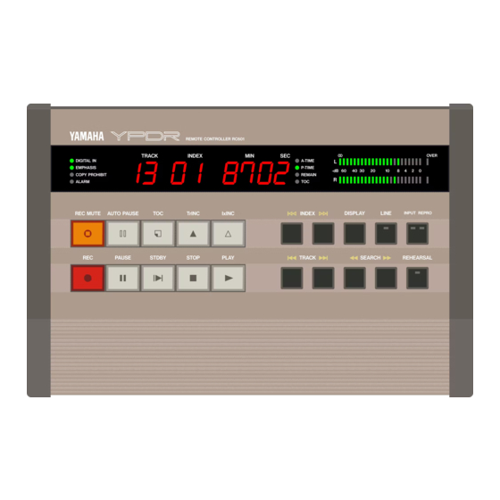
Page 16: Remote Controller (Rc601)
4 • Remote controller (RC601) - Front panel 4 • Remote controller (RC601) 4.1 Front panel ® ©DIGITAL IN/EMPHASIS/COPY PROHIBIT/ALARM indicators These indicators show the status of the recorder unit in various circumstances; The DIGITAL IN indicator lights when the INPUT SELECT switches (5) are set to DIGITAL. -
Page 17: Display
4 • Remote controller (RC601) - Front panel iii) If the copy protect flag is not set on the source, and the rear panel COPY GUARD switch is set to OFF, the copy-protect flag will not be written to disc, and the indicator will not light. The ALARM indicator lights if an error condition occurs. -
Page 18: Transport Controls
4 • Remote controller (RC601) - Front panel as this indicates digital clipping. A PEAK HOLD function for these meters is available through a rear panel switch. Note that this peak hold function is not a "permanent" peak hold - the peak segments of the meters "drop back" after a few seconds. -
Page 19: Rear Panel
4 • Remote controller (RC601) - Rear panel 4.2 Rear panel (T) PHONES connector A stereo 1/4" connector for headphone monitoring of the signal selected using the INPUT/REPRO key on the front panel. (D PHONES LEVEL A level control for the headphones connected to the PHONES connector (1). This control has no effect on the output level from the main unit. -
Page 20: Input Select Switches
4 • Remote controller (RC601) - Rear panel (5) INPUT SELECT switches These determine the type of source. The first switch allows selects either analog or digital input, and the second selects the typ>e of digital source; either AES/EBU or SDIF-II (D.IN). If the first switch is set to ANALOG, the position of the second switch has no effect. -
Page 21: Connection
(either analog or digital). This is best achieved by routing the source signal through a mixing console (in the case of a digital signal, a console such as the YAMAHA DMC1000 is ideal). 5.2 Single-recorder connection This configuration is used when recording from a stereo source onto disc. -
Page 22: Analog Input Level Adjustment
5 • Connection - Single-recorder connection • Set the DRIVE ID switch on the main unit to "0". • Connect the CONTROL connector of the controller to the I/O IN of the main unit. • Connect the terminator block to the I/O OUT of the main unit. •... -
Page 23: Multi-Recorder Connection
5 • Connection - Multi-recorder connection 5.3 Multi-recorder connection This configuration allows simultaneous recording multiple discs. principles for multi-recorder operation are essentially the same as for single-re corder operation. Since the 50-way cable carries digital audio as well as control information, up to seven recorder units may be "daisy-chained"... - Page 24 5 • Connection - Multi-recorder connection The DRIVE SELECT switch on the rear of the controller should be set to the num ber of recorder units connected, minus one. In the illustrated example, three units are connected, so this switch should be set to "2". The DRIVE ID switches of the recorder units should be set in sequence.
-
Page 25: Operation
6 • Operation - Playback of previously-recorded CDs 6 • Operation There are several basic methods of using the YPDR described here. Many of the basic operations are common to all methods. 6.1 Playback of previously-recorded CDs The YPDR may be used as a CD player to play back discs recorded on the YPDR. -
Page 26: Track And Index Location
6 • Operation - Recording fixed tracks (TOC PRE mode) Use the PLAY key to start replaying the disc. The PAUSE key, as well as the STOP key, can be used to halt playback. 6.1.2 Track and index location When the YPDR is in PLAY mode, the TRACK and INDEX keys can be used to locate the start of playback by track, or by index. -
Page 27: Recording The Toc
6 • Operation - Recording fixed tracks (TOC PRE mode) 6.2.1 Recording the TOC Set the TOC PRE/AFTER switch on the rear panel of the controller to "PRE", and the 10/30 switch beside it to either "1 OS" or "30S" (the track length in seconds). Load the disc into the main unit, as described in "Playback of previously-record... -
Page 28: Levels
6 • Operation - Recording fixed tracks (TOC PRE mode) tor ("PLAY1" and "PLAY2" messages will also be sent from the PARALLEL I/O connector. See the "Parallel I/O timing chart" on page 35 for details). This allows the simultaneous start of source machines capable of receiving these com mands. -
Page 29: Rec Mute
6 • Operation - Recording variable tracks (TOC AFTER mode) ment) key can be used to write index markers after the index number in the dis play has changed to "01". REC MUTE The REC MUTE key will mute the signal from the source while recording is m progress. -
Page 30: Track Start
6 • Operation - Recording variable tracks (TOC AFTER mode) "OOOObd". When a blank disc is inserted, the display will show If a disc already containing audio data but no TOC data is inserted, the display will show "xxOOAd", "xx" where is equal to the number of tracks already recorded. -
Page 31: Rec Mute
6 • Operation - Multi-recorder recording REC MUTE The REC MUTE key can be used to mute the source signal. However, the source signal can still be monitored using the LINE and INPUT/REPRO keys. The REC MUTE key is latching (push once to turn on, push again to turn it off). PAUSE The PAUSE key will temporarily halt recording, and will send a "STOP"... -
Page 32: Duplication
6 • Operation - Duplication Recording may be carried out only in the TOC AFTER mode. Operation is the same as for single-unit operation. If recording is to be carried out in multi-recorder mode, then the discs in all the recorder units should contain identical information. - Page 33 6 • Operation - Duplication indicator will come on. Unit N will enter PLAY/PAUSE mode, and the other units will go into REC/PAUSE mode. Press PLAY and REC together when the STDBY key is lit steadily. REC and PLAY will light, and will go off when the duplication process is complete. The STOP, PAUSE, REC or TOC keys will interrupt the duplication process.
-
Page 34: Errors
7 • Errors 7 • Errors It is possible that an internal error will occur while the YPDR is being operated. This will cause the ERROR indicator on the main display to light, and also light the ALARM indicator on the controller front panel. Occasionally the ALARM in dicator on the controller will light, but the ERROR indicator on the main unit will not light. -
Page 35: Technical Specifications 8.1 Controller (Rc601)
8 • Technical specifications - Controller (RC601) 8 • Technical specifications 8.1 Controller (RC601) Operating temperature 0°C to 40“C (32°F to 104°F) Relative humidity 30% to 80% (non-condensing) Operating voltage 100VAC-240VAC (50/60Hz) Power consumption Max 13W Dimensions (WxHxD) 3 1 0 x 7 5 x 2 2 1 (mm) ( 1 2 . 2 x 3 x 8 . 7 (in)) Weight 2.4kg (5.3lbs) YPDR... -
Page 36: Recorder Unit (Ypdr601)
- 435 x 147 x 400 (mm) Dimensions (WxHxD) 15.75 (in)). When feet are removed, and rack ears fitted, the YPDR601 can be fitted into a 19" equipment rack, taking 3U of space Weight 14kg (30.9lbs) -
Page 37: 50-Pin I/O Connector Pinout
-REQ +1/0 -I/O GROUND GROUND 8.4 Serial REMOTE (D-sub 9-pin) The connector can transmit PLAY and STOP commands to the source tape re corder (e.g. the Yamaha DMR8 or DRU8) using industry-standard serial proto col. YPDR Technical specifications - 33... -
Page 38: Parallel I/O (D-Sub 15-Pin)
8 • Technical specifications - PARALLEL I/O (D-sub 15-pin) 8.5 PARALLEL I/O (D-sub 15-pin) Signal name PLAY1 PLAY2 STOP REC STOP REC PLAY REC PAUSE TrINC An IxlNC (I) signal is eqivalent to a REC PLAY and a TrINC signal being trans mitted simultaneously (both REC PLAY and TrlNC go low at the same time). -
Page 39: Parallel I/O Timing Chart
8 • Technical specifications - PARALLEL I/O (D-sub 15-pin) 8.5.1 Parallel I/O timing chart OUT PUT [RECHPLAYl ---1 PLAY 1 PLAY 2 —\J*- Tw (Output) 20 ms ■= STOP STOP START REMOTE INPUT SIGNAL INPUT REC PLAY Tw (Input) > 40 ms Tr INC REC PAUSE ■U... - Page 40 Fixed track lengths REMAIN Focus lock error REMOTE connector Head lock 5, 11,30 SDIF-II 10, 15, 18,20 Headphone monitoring SEARCH Headphones Search HIGH/LOW switch Single-recorder connection Specifications RC601 I/O transmission failure YPDR601 INDEX Speed (spindle) lock Initialization tracking error YPDR...
- Page 41 TOC PRE TRACK Track and index location TRACK display Track start structure Transport controls Trimmer controls 9, 14, 24, 26 TrINC Variable track lengths 5, 10 Voltage selector Warm-up 15, 18, 20 Word clock Wrong kind of disc YPDR601 YPDR...
- Page 42 YAMAHA YAMAHA CORPORATION 10-1 NAKAZi-WA-CHO HAMAMATSU, JAPAN VK4984i;-0 iYinfed in Japan BWWB, bC®...