
Related Manuals for Honeywell VM3AL0N


Summary of Contents for Honeywell VM3AL0N
- Page 1 Thor™ VM3A Vehicle-Mount Computer Powered by Android™ Quick Start Guide VM3A-EN-QS-01 Rev A 01/20...
- Page 2 Out of the Box Make sure your shipping box contains these items: • Thor VM3A vehicle-mounted computer (Model VM3AL0N) • Regulatory Sheet If you ordered additional accessories for your computer, verify that they are also included with the order. Be sure to keep the original packaging in case you need to return the computer for service.
-
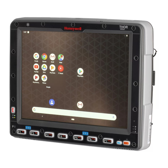
Page 3: Computer Features
Computer Features Front NFC Antenna Touch Panel Volume Brightness Power Controls Controls Button System Status Network LEDs Connection LEDs Speakers Shift Keys... - Page 4 Back Wi-Fi/BT Antenna SD memory expansion connections access panel Factory debug access panel DC Power Input COM USB, and Audio Power Button...
- Page 5 Dock Features Dock Contact Pads Standard Dock Ram Ball Wi-Fi Wi-Fi (Main) (Aux) Fuse Com 1 Power Connector Com 2 Audio Power Switch...
- Page 6 Mount to Vehicle The Thor VM3A should be secured to an area in the vehicle where it: • Does not obstruct the driver's vision or safe vehicle operation. • Will be protected from rain or inclement weather. • Will be protected from extremely high concentrations of dust or wind-blown debris.
- Page 7 Attach RAM ball to the Smart Dock.
- Page 8 Attach VM3A assembly to RAM base using RAM arm and tighten knob on RAM arm. For more mounting details, refer to the user guide available at www.honeywellaidc.com.
- Page 9 Connecting the Power Cable for 12-48 VDC Vehicles (10-60 VDC Direct Connection) Note: Refer to the Thor VM3A User Guide for other power connections, available at www.honeywellaidc.com. Caution: For installation by trained service personnel only. Warning: Fuse Requirements For proper and safe installation, the input power cable must be connected to a fused circuit on the vehicle.
- Page 10 Power Cable Routing...
- Page 11 Power Cable Wiring Diagram with Right Angle and 6 Wires Twist the red and red/white wires together and twist the black and black/white wires together before connecting to vehicle power. Connect the green wire to vehicle ground: Caution: For battery powered vehicles, the green wire must be connected to the vehicle chassis ground.
- Page 12 Vehicle 10-60 VDC Direct Power Connection The VM3A must not be mounted in the dock. The power switch on the dock must be turned Off. The power cable must be UNPLUGGED from the dock. Install the proper fuse based on the voltage source you will connect to.
- Page 13 • Auto On Control and Manual Control Wiring Diagram Ignition wire must be left disconnected. Existing Circuitry On Vehicle Quick Mount Smart Dock Battery Main Switch Cable for optional COM1 or COM2 screen blanking Connector connection Fuse - See Fuse Warning Red/White (if present) Black/White (if present) Circular...
- Page 14 from chemicals or oil that cause the insulation to deteriorate. Avoid sharp bends. The power cable is less flexible in low temperature environments. Secure the cable to the vehicle structure at approximately one foot intervals, taking care not to over tighten, pinch conductors, or penetrate the insulation.
-
Page 15: Restart The Computer
Restart the Computer You may need to restart the computer to correct conditions where an application stops responding to the system or the computer seems to be locked up. Press and hold the Power button until the options menu appears. Select Reboot and then OK. -
Page 16: User Documentation
Support To search our knowledge base for a solution or to log into the Technical Support portal and report a problem, go to www.hsmcontactsupport.com. User Documentation For the user guide and other documentation, go to www.honeywellaidc.com. Limited Warranty For warranty information, go to www.honeywellaidc.com click Get Resources >... - Page 17 Disclaimer Honeywell International Inc. (“HII”) reserves the right to make changes in specifications and other information contained in this document without prior notice, and the reader should in all cases consult HII to determine whether any such changes have been made. The information in this publication does not repre- sent a commitment on the part of HII.