Table of Contents
Quick Links
Table of Contents

Related Manuals for Siemens 8DA10 Series


Summary of Contents for Siemens 8DA10 Series
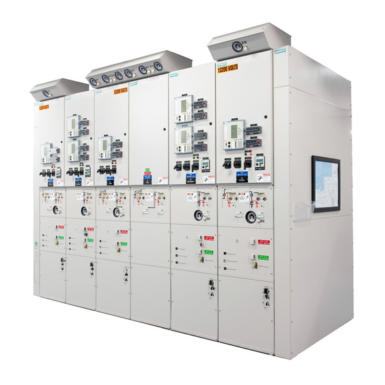
- Page 1 Medium-Voltage Switchgear Type 8DA10 Extendable Fixed-Mounted Circuit-Breaker Switchgear up to 40.5 kV Single Busbar, Single-Pole Metal-Enclosed, Gas-Insulated Medium-Voltage Switchgear INSTALLATION AND OPERATING INSTRUCTIONS Order No.: 861-9601.9 Revision: 11 Issue: 07-11-2017...
- Page 2 The Sales Contract contains variations in equipment. These instructions also cannot the entire obligations of Siemens. The warranty contained provide for every possible contingency to be met in in the contract between the parties is the sole warranty of connection with installation, combination of components, Siemens.
-
Page 3: Table Of Contents
Contents Safety instructions ..........6 Installation............40 Signal terms and definitions ....... 6 Constructional stipulations ....... 40 General instructions ........... 7 18.1 Switchgear room..........40 IT security ............9 18.2 Constructional data of the foundation ....43 Due application ..........9 18.3 Transport units.......... - Page 4 24.1 Installation of voltage transformers Operation ............150 type 4MT3 on the busbar ....... 107 Control elements and indicators..... 151 24.2 Installation of voltage transformers 34.1 Control elements and indicators of type 4MU4 on the busbar....... 111 the circuit-breaker.......... 152 24.3 Installation of voltage transformers 34.2 Control elements and indicators of type 4MT7 at the cable feeder......
- Page 5 41.1 Maintenance of the vacuum circuit-breaker End of service life ........... 209 operating mechanism........204 Siemens Service Hotline ......... 210 41.2 Procedure for bolted joints and seals ....207 Index ............... 211 41.3 Cleaning agents and cleaning aids ....207 41.4 Lubricants ............
-
Page 6: Safety Instructions
Safety instructions Safety instructions Signal terms and definitions The signal words "danger," "warning" and "caution" used in this instruction manual indicate the degree of hazard that may be encountered by the user. DANGER Danger - Indicates an imminently hazardous situation. If this hazardous situation is not avoided, death or serious injury will be the consequence. -
Page 7: General Instructions
Safety instructions General instructions DANGER Hazardous voltages and high-speed moving parts Will cause death, serious injury or property damage. ➭ Always de-energize and earth the switchgear before maintenance. ➭ Read and understand this instruction manual before using switchgear. ➭ Maintenance should be performed only by qualified personnel. The use of unauthorized parts in the repair of the switchgear or tampering by unqualified personnel will result in dangerous conditions that will cause death, severe injury or switchgear damage. - Page 8 ➭ After installation and setting, have a final check performed by a service engineer approved by Siemens, including documentation of the test results. ➭ Perform maintenance according to the operating instructions of the Siemens products. The switchgear corresponds to the relevant laws, prescriptions and standards applicable at the time of delivery.
-
Page 9: Security
IT security The Siemens software is regularly checked for safety. If weak points are identified in the process, which may allow third parties to access protection devices, information thereto is distributed through the SIPROTEC and SICAM Security Update Report Newsletter. -
Page 10: Qualified Personnel
• After first installation of switchgear type 8DA10 under supervision of a certified senior supervisor and his signature on the certificate, and • after proof in form of an installation record for the Siemens Switchgear Factory Frankfurt am Main. After having been issued by the Siemens Switchgear Factory Frankfurt am Main, the certificate is valid for three years. -
Page 11: Description
Description Description Panel overview Subframe • Support for switchpanel poles and panel front • Forms the cable compartment • Subframe versions - Standard: Switchgear height 2350 mm - Higher version: Switchgear height 2570 mm Switchpanel pole • Poles arranged one behind the other. •... -
Page 12: Examples For Panel Versions
Description Examples for panel versions Circuit-breaker panel Disconnector panel Bus sectionalizer Cable connection panel Metering panel Dummy panel Vacuum circuit- Plug-in voltage Three-position disconnector breaker transformer Plug-in cable Capacitive voltage These components are (not included in - - - - - - detecting system optionally selectable the scope of supply) -
Page 13: Examples For Panel Versions
Description Examples for panel versions Circuit-breaker panel up to 3150 A with fan ① Low-voltage compartment ② SIPROTEC bay controller (option) ③ Operating mechanism for three-position disconnector ④ Gas pressure manometer for switchpanel pole housing ⑤ Gas filling valve ⑥ Circuit-breaker operating mechanism ⑦... - Page 14 Description Three-position disconnector panel up to 3150 A ① Low-voltage compartment ② SIPROTEC bay controller (option) ③ Operating mechanism of three-position disconnector ④ Gas pressure manometer for switchpanel pole housing ⑤ Gas filling valve ⑥ Capacitive voltage detecting system ⑦ Busbar housing ⑧...
-
Page 15: Low-Voltage Compartment
Description Bus sectionalizer up to 3150 A with fan ① Low-voltage compartment ② SIPROTEC bay controller (option) ③ Operating mechanism for three-position disconnector ④ Gas pressure manometer ⑤ Gas filling valve ⑥ Circuit-breaker operating mechanism ⑦ Capacitive voltage detecting system ⑧... -
Page 16: Circuit-Breaker
Description Circuit-breaker Design The vacuum circuit-breaker consists of the following components: • Operating mechanism with stored-energy spring mechanism and control elements (3AH49) • Operating linkage for contact operation • 3 switchpanel poles with vacuum interrupters Vacuum interrupters ① Moving contact ②... -
Page 17: Equipment
Description Function Depending on its equipment, the circuit-breaker is closed mechanically by means of an ON pushbutton, or electrically. The operating power is transmitted to the vacuum interrupters through an operating linkage. In case of a motor operating mechanism, the closing spring is charged by means of a motor and latched in the charged position. -
Page 18: Three-Position Disconnector
Description Three-position disconnector Function The three-position disconnector combines the functions of a disconnector and an earthing switch. The three-position disconnector is designed for no-load operation only. ① Fixed contact, busbar ② Busbar housing ③ Busbar ④ Busbar support ⑤ Fixed contact, earth ⑥... - Page 19 Description Operating mechanism for three-position disconnector The three-position disconnector is operated from the switchgear front. • Auxiliary switch - Every operating mechanism is equipped with an auxiliary switch to indicate the switch position. • Motor operating mechanism - Remote operation (standard) - Local operation (option) - Manual operation possible by operating lever •...
-
Page 20: Make-Proof Busbar Earthing Switch
Description Make-proof busbar earthing switch ① Operating mechanism housing of busbar earthing switch ② Position indicator ③ Actuating opening The busbar earthing switch is an earthing switch with short-circuit making capacity for make-proof earthing of the busbar. 20/214 Revision 11 • INSTALLATION AND OPERATING INSTRUCTIONS • 8DA10 • 861-9601.9... -
Page 21: Current And Voltage Transformers
Description Current and voltage transformers 10.1 4MT and 4MU voltage transformers Features • According to IEC 61869-3 • Cast-resin insulated • Inductive type • Safe-to-touch due to metal enclosure Mounting locations • On the busbar • At the panel connection housing Fig. - Page 22 Description Damping resistor for voltage transformers • Damping resistor for voltage transformers at the panel connection housing ① • Damping resistor for voltage transformers on the busbar ② Fig. 8: Position of damping resistors in the switchgear frame 22/214 Revision 11 • INSTALLATION AND OPERATING INSTRUCTIONS • 8DA10 • 861-9601.9...
-
Page 23: Current Transformers
Description 10.2 Current transformers Features • According to IEC 61869-2 or EN 61869-2 (depending on the switchgear version) • Designed as ring-core current transformers: - Ring core as carrier of secondary winding - Main circuit corresponds to primary winding • Arranged outside the primary enclosure (switchgear housing) due to single-pole design of the panel •... -
Page 24: Gas Compartments
The following example shows the distribution of the gas compartments with the associated item designations of the manometers. For further information, please contact the Siemens Service Hotline. ① Busbar in phase L1 (manometer B11) ②... -
Page 25: Panel Connection
Description Panel connection 12.1 Features • Bushings for plugs with inside-cone plug-in system according to EN 50181 • Single and multiple connections possible per phase • Conection of several cables with different plug sizes possible per phase • Connection of solid-insulated or gas-insulated bar possible •... - Page 26 Description Version 3 4MT7 Solid-insulated bar connection Version 4 Solid-insulated bar connection Version 5 26/214 Revision 11 • INSTALLATION AND OPERATING INSTRUCTIONS • 8DA10 • 861-9601.9...
-
Page 27: Protection And Control Equipment
Description Version 6 Solid-insulated bar connection Version 7 Gas-insulated bar connection Protection and control equipment The protection equipment and control equipment is designed customer-specifically. T he devices are installed in the low-voltage compartment or in the low-voltage niche. Details are given in the respective circuit documentation. Voltage detecting systems For voltage detection according to IEC 61243-5 and VDE 0682 Part 415 with the following voltage detecting systems:... -
Page 28: Aseismic Design (Option)
Description Aseismic design (option) Seismic withstand 8DA10 switchgear can be upgraded for operation in regions at risk from earthquakes, capability (option) see the relevant order and delivery documents. The additional components for earthquake-resistant design are pre-assembled at the factory. ① Reinforced side plate ②... -
Page 29: Accessories
Description Accessories 16.1 Standard accessories • Operating and installation instructions • Operating lever for three-position disconnector: DISCONNECTING function • Operating lever for three-position disconnector: EARTHING and READY-TO-EARTH function • Hand crank for charging the circuit-breaker closing spring • Double-bit key with a diameter of 3 mm (for door of low-voltage compartment) •... -
Page 30: Other Accessories
Description 16.2 Other accessories Other accessories According to the order documents / purchase order (selection): • Plug-in voltage indicators for LRM systems • Unit to test the function of the plug-in voltage indicators • Units to test the capacitive interface and the voltage indicators •... -
Page 31: Technical Data
Description Technical data 17.1 Electrical data Complete switchgear Electrical data, filling pressure, temperature for single-busbar switchgear Rated insulation level Rated voltage U 40.5 Rated short-duration power-frequency withstand voltage U - phase-to-earth, open contact gap - across the isolating distance Rated lightning impulse withstand voltage U - phase-to-earth, open contact gap - across the isolating distance Rated frequency f... -
Page 32: Vacuum Circuit-Breaker
Description Circuit-breaker panel, disconnector panel Data of the switchgear panels (circuit-breaker panel, disconnector panel, bus sectionalizer, cable connection panel, metering panel) Rated voltage U 40.5 1250 Rated normal current I 1600 2000 2500 2750 3150 Rated short-time withstand current I = 3 s up to kA 50 Hz... - Page 33 Description Close-open contact time The interval of time - in a make-break operating cycle - between the instant when the contacts touch in the first pole in the closing process, and the instant when the contacts of the internal arc contact separate in all poles in the subsequent opening process. Motor operating The operating mechanisms of the 3AH49 circuit-breakers are suitable for auto-reclosing.
-
Page 34: Endurance Classes
Description Integrated varistor NOTICE Overvoltages in inductive circuits Electrical control devices can be damaged by switching overvoltages. ➭ Do not switch off inductive consumers in DC circuits. The integrated varistor limits overvoltages to approx. 500 V for • protection devices (when inductive components are mounted in the vacuum circuit- breaker) •... -
Page 35: Insulating Gas
Description 17.4 Insulating gas The sealed pressure system of the switchgear contains the insulating gas SF (fluorinated greenhouse gas, GWP 22,800). Example for a typical amount of SF gas: 8DA10 circuit-breaker panel 36 kV, 40 kA, 1250 A, cable connection 2 x plug size S3 with 2.8 kg SF e = 64t). - Page 36 Description Busbar housing Rated busbar current 1250 3150 2000 4000 2500 5000 Rated lightning impulse withstand voltage ≤ 170 > 170 Rated short-duration power-frequency ≤ 70 > 70 withstand voltage Rated functional level Min. functional level Signal "pressure low" Signal "pressure very low" Max.
-
Page 37: Classification Of 8Da10 According To
Description 17.5 Classification of 8DA10 according to IEC 62 271-200 DANGER Internal arcing and explosion hazard Will cause death, serious injury or property damage. The switchgear may or may not be classified as arc-resistant switchgear. If the switchgear has internal arc classification IAC A FL, the area behind the switchgear is not tested to evaluate the effects of internal arcs. -
Page 38: Phase Sequence
In this way, the switchgear assemblies of this type series fulfill the basic protection requirements of the EMC Directive. Protection against solid The fixed-mounted circuit-breaker switchgear of the 8DA10 series fulfills the following degrees foreign objects, electric of protection according to IEC 62271-1, IEC 62271-200, IEC 60529 and IEC 62262: shock and water •... -
Page 39: Rating Plates
Description 17.8 Rating plates Switchgear panel The rating plate contains all information that is binding for the panel and its components. The rating plate is located: • On the inside of the low-voltage compartment door (rating plates for panel, optionally for voltage transformers and current transformers) If the circuit-breaker class is specified as M2, a maximum of 10000 (optionally 30000) mechanical operating cycles are possible with the circuit-breaker. -
Page 40: Installation
Installation Installation Constructional stipulations 18.1 Switchgear room The switchgear can be used at the following locations as an indoor installation according to IEC 61936 (Power Installations exceeding AC 1 kV) and VDE 0101: • Lockable electrical service locations. Requirements on lockable electrical service locations (room or location): - Are exclusively used for operation of electrical equipment. - Page 41 Installation Room dimensions and wall distances Fig. 20: Wall-standing arrangement Fig. 21: Free-standing arrangement *) Depending on national requirements **) Lateral wall distance ≥ 500 mm optionally required on the left or on the right ***) Lateral minimum wall distance ≥ 100 mm optionally possible on the left or on the right Load-bearing capacity of Load data the floor...
- Page 42 Installation Construction of the floor The floor covering must be even, easy to clean, pressure-resistant, slip-resistant, abrasion- resistant and electrically discharging. As floor construction, the following is possible: Steel girder layer Suitable for large and numerous floor openings, and advantageous for later modifications or extensions of the switchgear.
-
Page 43: Constructional Data Of The Foundation
Installation 18.2 Constructional data of the foundation Floor openings The panels can be bolted or welded to the foundation rails. Fasten each panel diagonally to the foundation rails at two points at least. Use M10 fixing bolts as a minimum. Tightening torque: 60 Nm. - Page 44 Installation Welded joint of the Weld the standard design diagonally to the foundation rails at 2 points. A floor fixing profile is standard design not necessary. The welded seams must conform to the strength of an equivalent bolted joint with M10 bolts. Fig.
-
Page 45: Transport Units
Installation 18.3 Transport units Dimensions Panel widths Transport dimensions Transport weight with Transport weight packing without packing Width x Height x Depth approx. kg approx. kg mm x mm x mm Means of transport: Truck 1 x 600 1370 x 2550 x 1888 2 x 600 1764 x 2550 x 1870 1700... -
Page 46: Before Installation
Before installation 19.1 Preliminary clarifications In order to load the transport units in a suitable installation order, the responsible Siemens representative requires the following information from you several weeks before delivering the switchgear: • Sketch of the installation room including the locations and numbers of the individual panels and the storage space for the accessories •... -
Page 47: Overview Of Busbar Housing Covers With Desiccant Bags
- Length of lifting rod for a double panel 1600 mm - Increase the length of the lifting rod by + 600 mmfor each further panel - Certified lifting rods may be procured from the local Siemens representative. • Chain with transport shackles •... -
Page 48: Tightening Torques
Installation Type of housing cover Front view Rear view Busbar housing cover with bursting disc and desiccant bag holder for 2x 250 g desiccant bags ① • Adhesive label: Filter Busbar housing post insulator cover without desiccant holder ② • Adhesive label: Busbar direction Busbar housing post insulator cover with desiccant holder for 1x 450 g desiccant bag... -
Page 49: Comments On Electromagnetic Compatibility
Installation 19.6 Comments on electromagnetic compatibility To achieve appropriate electromagnetic compatibility (EMC), some basic requirements must be observed while erecting the switchgear. This applies especially to the installation and connection of external cables and wires. Basic measures for ensuring EMC are already taken during design and assembly of the switchgear panels. -
Page 50: Transport And Storage
➭ As far as possible, document larger defects and transport damages photographically; prepare a damage report and inform your regional Siemens representative immediately. ➭ Have the transport damages repaired, otherwise you may not start installation. - Page 51 Installation WARNING Fire risk The transport unit is packed in flammable materials. ➭ No smoking. ➭ Keep fire extinguishers in a weatherproof place. ➭ Mark the location of the fire extinguisher. NOTICE Damaged packings of desiccant bags Can cause corrosion of switchgear parts and formation of creepage distances by high air humidity.
- Page 52 ➭ If there is no sufficient knowledge about professional regeneration of the packing: Ask for expert personnel via the competent Siemens representative. ➭ Open the packings. ➭ Replace the desiccant bags by the same number of new desiccant bags.
-
Page 53: Transporting And Unloading The Transport Unit
Installation 20.4 Transporting and unloading the transport unit CAUTION Risk of property damage If the panels are transported without transport blocks (fixing brackets) at the busbars, parts of the switchgear may be damaged. ➭ Do not remove the transport blocks until right before assembling the busbars. ➭... - Page 54 Minimum length of the lifting rods: Width of transport unit plus 400 mm. transport pallet Certified lifting rods for different panel widths are available at the regional Siemens representative. Fig. 32: Certified lifting rod for panels of 8DA10 ①...
- Page 55 Installation The transport holes for pushing the lifting rods in are marked on the transport unit with a red symbol. Fig. 33: Position of transport holes Fig. 34: Marking of transport holes ➭ If necessary, remove the switchgear termination. ➭ Push the lifting rods into the transport holes at the front and at the rear. ➭...
-
Page 56: Setting Down The Transport Units At The Place Of Installation
Installation Lifting the transport unit WARNING with hydraulic or lifting jacks If it is lifted unevenly, the transport unit can fall over due to its high center of gravity. If a transport unit falls down on a person, this can cause life-endangering injuries. ➭... - Page 57 Installation DANGER Risk of injury due to transport unit falling over. Will cause death, injury or considerable property damage. Bridge floor openings that have to be crossed. When it is shifted, the transport unit may slip off the bridge and fall over. ➭...
- Page 58 Installation Setting down the The transport units are set down in front of the long side of the floor opening to the cable transport units from the basement, and are pushed over the floor opening. long side of the floor opening ①...
-
Page 59: Aligning The Switchgear
Installation 20.6 Aligning the switchgear ➭ Align the first transport unit (end panel) completely and bolt it to the foundation (see page 43, "Constructional data of the foundation"). ➭ Just align the other transport units (panels) roughly first. ➭ Keep a distance of at least 500 mmbetween the transport units for the subsequent installation work. -
Page 60: Checking The Sf6 Gas Pressure
➭ Do not install, commission or operate a switchgear with incorrect or too low SF pressures. If required, isolate the switchgear and put it out of service. ➭ Inform the competent regional Siemens representative. ① Gas pressure manometers for the busbar compartments ②... -
Page 61: Switchgear Installation
Installation Switchgear installation WARNING Risk of injury due to inappropriate installation. The activities described below must be performed professionally in order to minimize the risk of injury. ➭ The switchgear must be assembled by certified personnel only (see page 10, "Qualified personnel"). Fig. -
Page 62: Preparing Busbar Assembly
Installation 21.1 Preparing busbar assembly Removing CAUTION transport blocks Risk of property damage If the panels are transported without transport blocks (fixing brackets) at the busbars, parts of the switchgear may be damaged. ➭ Do not remove the transport blocks until right before assembling the busbars. ➭... - Page 63 Installation Preparing This operation is only performed if there is a horizontal flange cover available on the busbar busbar assembly on housing of the right end panel. the right end panel ➭ Remove all flange covers ② from the assembly openings of the short busbar housing ① . ➭...
- Page 64 ➭ Carefully check the sealing surfaces ③ of the flanges for scratches, other damages or pollution. Damages and pollution will cause leaks. ➭ If the sealing surfaces ③ are damaged: Inform the regional Siemens representative and coordinate the elimination of damages.
- Page 65 Installation Preparing the busbar ➭ Undo the bolted joints ① and ② . sections ➭ Remove the bolted joint ③ . Fig. 47: Bolted joints at the busbar section ➭ Clean the links at the busbar sections using an emery sponge and a lint-free cloth. Then, apply a very thin film of the supplied mounting paste.
- Page 66 • Disconnectable busbar voltage transformer For other disconnectable components, e.g. make-proof busbar earthing switch, the busbar joints are not accessible anymore after the transport units have been interconnected. For further information, please contact the Siemens Service Hotline. NOTICE Damage to the busbar support The busbar support keeps the busbar with a weight of approx.
- Page 67 Installation Preparing busbar This operation is only performed if there is a horizontal flange cover available on the busbar assembly on the panel to housing of the panel to be lined up. be lined up NOTICE Risk of property damage During assembly of the 4000 A busbar, there is risk of property damage in case of re- assembling the busbar into the panel to be lined up.
- Page 68 Installation ➭ Mark the position from the transformer connection housing ② to the busbar housing ④ by two lines offset by 90°. The lines serve as positioning aid for later assembly. Fig. 52: Positioning aids (zooms show side views) ➭ Remove the bolted joint ⑥ between the transformer connection housing ② and the busbar housing ④...
- Page 69 Installation Fig. 55: Inserting the busbar ① Busbar in the fixed-mounted panel ② Upper connecting bar ③ Upper disconnector contact ④ Cup head bolt with hexagon nut and conical spring washer (5x) ⑤ Busbar in the panel to be lined up ⑥...
- Page 70 Installation ➭ Fit the protective caps on the bolted joints of the busbar. ① Busbar in the fixed- mounted panel ② Cup head bolt M10x65 with hexagon nut and conical spring washer ③ Upper disconnector contact ④ Protective caps (9x) ⑤...
-
Page 71: Lining Up Panels
Installation 21.2 Lining up panels Positioning the panel The panel to be lined up is moved evenly by two people, if possible, using hydraulic hoisting cylinders, hydraulic jacks or lifting jacks. A third person acts as an observer and corrects the joining of the busbar sections and the flanges during the process. - Page 72 Installation Bolting the flanges of the NOTICE busbar housings together Risk of damage to property Sensitive parts of the switchgear may be damaged during installation work at the busbar and the busbar housings. ➭ While working at the busbars or the busbar housings, prop up only on the base frame of the transport unit.
- Page 73 Installation ➭ Flange connections with current transformer: If there are busbar current transformers or expansion joints available, the flange connections must be equipped with insulating sleeves. Slide two insulating rings between the flanges. Fasten M8x45 bolts crosswise with one insulating sleeve each (tightening torque: 20 Nm). ①...
-
Page 74: Lining Up Further Panels
Installation 21.3 Lining up further panels ➭ Repeat the work operations (see page 64, "Preparing the flanges of the busbar housings") until all panels are installed. INFORMATION If required, mount loosely delivered panel connections and earthing busbars before lining up another panel. - Page 75 Installation ➭ Modify the length of the disconnector coupling rod by turning the hexagonal sleeve ① , so that the contact fingers are resting exactly on the fixed contact of the disconnector in CLOSED position. Fig. 66: Example for correct and incorrect position of the contact fingers on the fixed contact ➭...
- Page 76 Installation Panel links for The frames of the panel groups pre-assembled at the factory are bolted together at the panel panel groups delivered by joints at the front ① and rear ② with one panel link each. the factory ① Large panel link (front) ②...
-
Page 77: Mounting The Cable Bracket
Installation ➭ Bolted joint an the front of the panels: Bolt the small panel links at the top and bottom in the fixed-mounted panel together with the front part of the frame at the panel to be lined up. Thread the upper panel link through the slot of the front support. Use 2 cup head bolts M10x20, plain washers and hexagon nuts for each small panel link (tightening torque: 40 Nm). - Page 78 Installation Fig. 72: Mounting the cable bracket at the cross members ① ④ Cage nut Contact washer ② Cable bracket ⑤ Hexagon head bolt M10x40 ③ Hexagon nut M12 (used as spacer) ➭ Mount the cable plugs. ➭ Fasten the cables at the cable bracket using cable clamps. ➭...
-
Page 79: Installing The Earthing Busbar
Installation 21.6 Installing the earthing busbar Earthing busbars at the switchgear Earthing busbars at the The earthing busbar runs at the rear of the switchgear frames. The units of the earthing intermediate panel busbars overlap. The earthing busbars are interconnected with two bolts M12 and a tightening torque of 70 Nm each. - Page 80 Installation Earthing busbars at the end panel Fig. 75: Earthing busbars at the end panel ① Short-circuit bridge at the circuit-breaker housing ② 2x M12 with contact washers, conical spring washers and nuts at the joint ③ Earthing busbar connection to the next panel Short-circuit bridge at the panel connection housing If the panel connection housings are delivered separately, the short-circuit bridge ③...
- Page 81 Installation ➭ Repeat the assembly operations for the short-circuit bridges at the panel connection housings until all bar ends of the switchgear are interconnected. Fig. 77: Earthing at the short-circuit bridge of the panel connection housings (work-in-progress earthing) Earthing the panels The cross-sections and materials of the earthing conductors are specified in the DIN/VDE 0101 or IEC 61936-1 standard and in the relevant country-specific standards.
- Page 82 Installation Optional earthing bar The optional earthing bar for the panel connection is supplied loosely. It must be mounted on site. The optional earthing bar consists of two vertical and one horizontal earthing bars. Determine the height of the horizontal earthing bar ① . Use one cup head bolt M12x40, one conical spring washer and one hexagon nut to bolt the horizontal earthing bar together with the two vertical earthing bars.
- Page 83 Installation Mounting the short-circuit bridge on the bus sectionalizer In the case of the bus sectionalizer, the short-circuit bridge ① must be mounted on site. Fig. 81: Fixing points at the short-circuit bridge The earthing busbars of the switchgear frame are pre-assembled at the factory. Mount the short-circuit bridge at the bus sectionalizer housings as follows: ➭...
-
Page 84: Interconnecting Panels With 5000 A Busbar (Twin Busbar)
Installation 21.7 Interconnecting panels with 5000 A busbar (twin busbar) Fig. 84: Busbar version 5000 A (twin busbar) Preparations: Removing upper row of busbar housings The upper row of busbar housings has been pre-assembled at the factory. To interconnect the panels, this row must first be dismantled. Fig. - Page 85 Installation ➭ Remove the earthing bar ① . To do this, loosen the three hexagon head bolts M12x30. Fig. 86: Removing the earthing bar ➭ Detach the coupling rod ① (option) from all upper busbar housings. Fig. 87: Detaching the coupling rod ① (option) ➭...
- Page 86 Installation ➭ Remove the busbars ④ linked to the twin busbar connection. To do this, remove the four hexagon nuts M10 with plain washers ① . Secure the two links ② against falling down, and take the three busbars ④ out carefully. Fig.
- Page 87 Installation ➭ Loosen the bolted joint between the upper row of busbar housings ① and the lower row of busbar housings ④ . To do this, undo the eight bolt-and-washer assemblies M8 ③ . ① Busbar housing (upper row) ② Supporting angle ③...
- Page 88 Installation Fig. 92: Panel after removal of upper busbar housing system Assembly aid WARNING Risk of falling due to uncovered openings and cutouts A cover prevents the person from falling into or through an opening or a cutout. ➭ Provide for sufficient load-bearing capacity of the cover. ➭...
- Page 89 ➭ Carefully check the external contact surfaces of the flanges and the grooves for scratches and other damages or pollution. Damages and pollution will cause leaks. ➭ If any external contact surfaces or grooves are damaged: Inform the regional Siemens representative and coordinate the elimination of damages.
- Page 90 Installation Setting down and ➭ Set down the busbar housing. mounting the busbar housing Fig. 97: Setting down the busbar housing ➭ Align the housings to be interconnected using a suitable auxiliary means and bolt together. Fig. 98: Aligning the busbar housings 90/214 Revision 11 •...
- Page 91 Installation ➭ Use 8 bolt-and-washer assemblies M8 ③ in order to bolt busbar housings located one beneath the other together (tightening torque: 20 Nm). ➭ Use 8 bolt-and-washer assemblies M8 ① in order to bolt busbar housings located side by side together (tightening torque: 20 Nm).
- Page 92 Installation ➭ To simplify installation, bolt the three busbars together using one bar support (if not pre-assembled at the factory) Fig. 101: Inserting the busbars ➭ Interconnect the busbars and bolt them together at the twin busbar connection. Fig. 102: Bolting busbars together ➭...
- Page 93 Installation Installing disconnectable busbar components When disconnectable busbar components such as voltage transformers with fuses must be mounted, the kinematic system has to be assembled first. Assembling the ➭ The operating shaft with coupling rods ① at the upper row of busbar housings and the kinematic system operating shaft ②...
- Page 94 Installation Fig. 105: Mounting position of kinematic system at the upper and lower busbar housings ➭ Secure the rear end of the operating shaft ① with spring-type straight pins ② to prevent displacement of the operating shaft. Fig. 106: Securing the operating shaft ➭...
-
Page 95: Installation Work With Sf6 Gas Before Commissioning
Installation Installation work with SF gas before commissioning If a rated short-duration power-frequency withstand voltage test has to be carried out on site, the work with insulating sulfur hexafluoride gas (SF ) described in this section must be performed in advance. WARNING Danger of suffocation Inhaling high concentrations of SF... - Page 96 Installation ➭ Prepare the flanges of the busbar housings for assembly (see page 62, "Preparing busbar assembly"). ➭ Clean the sealing surfaces of the busbar housing covers with a lint-free paper, and apply a thin film of grease. ➭ Determine the size of the desiccant bags required for each busbar housing. ➭...
-
Page 97: Installing The Panel Connections Supplied
Installation Filling the busbar run ➭ Determine the filling pressure required according to the rating plate (see page 39, "Rating with SF plates") and the data given in Section "Insulating gas SF " (see page 35, "Insulating gas"). The pressure depends on the gas temperature. ➭... - Page 98 Installation ① Transformer housing ② Cover of transformer housing Fig. 110: Removing the cover of the transformer housing ➭ Remove the cover of the transformer housing ① and the sealing ring ③ . ① Cover of transformer housing ② Transformer housing ③...
- Page 99 ➭ Carefully check the external contact surface of the flange and the groove for scratches and other damages or pollution. Damages and pollution will cause leaks. ➭ If the external contact surface or the groove are damaged: Inform the regional Siemens representative and coordinate the elimination of damages.
- Page 100 ➭ Carefully check the external contact surface of the flange and the groove for scratches and other damages or pollution. Damages and pollution will cause leaks. ➭ If the external contact surface or the groove are damaged: Inform the regional Siemens representative and coordinate the elimination of damages.
- Page 101 Installation ➭ Grease the contact laminations ⑬ with mounting paste Vaseline 8422 DAB 8 (order number: 8BX2041). Fig. 119: Greasing the socket INFORMATION In other panel connection versions, the plug sockets may be arranged asymmetrically. ➭ If the plug sockets are arranged asymmetrically, observe the mounting direction of the cover at the panel connection housing.
- Page 102 Installation Replacing desiccant bags The desiccant bags are located behind the bursting disc cover at the side of the circuit-breaker in the circuit-breaker housing. The cover has the inscription "Filter" ① . housings Fig. 122: Bursting disc cover on circuit-breaker housing WARNING In the ambient air, the desiccant bags lose their effectiveness rapidly The formation of condensation can lead to corrosion of switchgear parts.
-
Page 103: Installing Solid-Insulated Bars At The Panel Connection, And Filling The Circuit-Breaker Housings With Sf6 Gas
Installation ➭ Undo the locking cap of the gas filling valve marked with B0 for the circuit-breaker housings. ➭ Connect the vacuum pump to the valve. Use short tubes with a large inside diameter. ➭ Evacuate the circuit-breaker housings down to a pressure of less than 2 kPa. Manometer indication: -100 kPa. - Page 104 Installation Mounting ➭ Repeat the following work operations for all solid-insulated bars in the same panel. solid-insulated bars ➭ Remove the provisional cover ① from one panel connection. Keep the removed bolts ④ and contact washers ③ for later installation. Dispose of the spacing nuts ② required for transport in an environmentally compatible way.
-
Page 105: Performing The Power- Frequency Voltage Test
Installation Performing the power- frequency voltage test If required, a test with rated short-duration power-frequency withstand voltage can be performed at the readily installed switchgear on site. The busbar voltage transformers are designed for a repeat test at 80% U at 60 Hz according to IEC 62271-200. -
Page 106: Installing The Voltage Transformers
Installation Installing the voltage transformers DANGER Hazardous voltage. Will cause death, serious injury and property damage. Always observe the Five Safety Rules: ➭ Isolate. ➭ Secure against reclosing. ➭ Verify safe isolation from supply. ➭ Earth and short-circuit. ➭ Cover or barrier adjacent live parts. DANGER Hazardous voltage Can cause death, injury or considerable property damage. -
Page 107: Installation Of Voltage Transformers Type 4Mt3 On The Busbar
Installation 24.1 Installation of voltage transformers type 4MT3 on the busbar ① 4MT3 voltage transformer ② Low-voltage plug connector ③ Adapter plate ④ Voltage transformer mounting plate ⑤ Busbar housing ⑥ Distance sleeves ⑦ Outside-cone bushing ⑧ Hole with setnut for press-out bolt Fig. - Page 108 Installation INFORMATION The already assembled adapter plate can be displaced due to vibrations during transport. To position the adapter plate correctly: ➭ Loosen the M8 bolts of the adapter plate a little bit. ➭ Bolt the adapter plate uniformly together with the voltage transformer mounting plate. Tightening torque: 30 Nm.
- Page 109 Installation NOTICE Risk of partial discharges at the outside-cone bushing. Damage to the switchgear can be the consequence. ➭ Make sure that the connecting lug of the capacitive connecting point of the outside-cone bushing is earthed. ➭ To let excess air out of the plug connection while mounting the voltage transformer, fit a nylon thread or a cable strap into the inside cone of the silicone adapter in the voltage transformer.
- Page 110 Installation ➭ Lower the voltage transformer slowly onto the bushing, pulling the cable strap out of the inside cone of the voltage transformer at the same time. ➭ Plug the low-voltage plug connectors in at the voltage transformers. ➭ Fasten the voltage transformer at the panel. To do this, bolt the voltage transformer uniformly together with the voltage transformer mounting plate using four M8 bolts.
-
Page 111: Installation Of Voltage Transformers Type 4Mu4 On The Busbar
Installation 24.2 Installation of voltage transformers type 4MU4 on the busbar ① Low-voltage plug connector ② Crane eye ③ Voltage transformer ④ Inside-cone bushing ⑤ Busbar housing ⑥ Voltage transformer mounting plate ⑦ Primary terminal at the voltage transformer ⑧ Silicone adapter Fig. - Page 112 Installation ➭ Insert one hexagon socket head bolt M8x25 (with pan head) each into the now free holes. Fig. 126: Inserting hexagon socket head bolts ➭ Clean the silicone adapter and the inside-cone cast-resin bush carefully. Use a cleaning agent without solvents and a lint-free cloth. ➭...
-
Page 113: Installation Of Voltage Transformers Type 4Mt7 At The Cable Feeder
Installation CAUTION Disruptive discharges due to air inclusions Will damage the cast-resin bushing. ➭ While installing the voltage transformer, let excess air out of the plug-in connection with a cable strap. ➭ Verify intact condition of the cable strap. If the cable strap was damaged when it was pulled out, remove the voltage transformer and eliminate the residues of the cable strap. - Page 114 Installation ➭ For first installation of the voltage transformer, mount the threaded rods M10 with low- design nuts (flat nuts) according to DIN 4035 on the panel connection cover (installation instruction enclosed with the supplementary equipment). ① Panel connection housing ②...
- Page 115 Installation WARNING Risk of injury while transporting the voltage transformer The voltage transformer may fall down during transport. Serious injury and property damage can be the consequence. ➭ Secure the voltage transformer against falling down. If required, use a support. ➭...
-
Page 116: Removing The Voltage Transformers
Installation Removing the voltage transformers DANGER Hazardous voltage. Will cause death, serious injury and property damage. Always observe the Five Safety Rules: ➭ Isolate. ➭ Secure against reclosing. ➭ Verify safe isolation from supply. ➭ Earth and short-circuit. ➭ Cover or barrier adjacent live parts. DANGER Hazardous voltage Can cause death, injury or considerable property damage. -
Page 117: Removal Of Voltage Transformers Type 4Mt3 From The Busbar
Installation 25.1 Removal of voltage transformers type 4MT3 from the busbar ① 4MT3 voltage transformer ② Low-voltage plug connector ③ Adapter plate ④ Voltage transformer mounting plate ⑤ Busbar housing ⑥ Distance sleeves ⑦ Outside-cone bushing ⑧ Hole with setnut for press-out bolts Fig. - Page 118 Installation CAUTION Voltage transformer falling down Can cause injury and property damage. While being removed from the bushing, the voltage transformer can detach suddenly. ➭ Remove the voltage transformer upwards as uniformly as possible. ➭ Adequately support the voltage transformer so that it cannot fall as it is being withdrawn. ➭...
-
Page 119: Removal Of Voltage Transformers Type 4Mu4 From The Busbar
Installation 25.2 Removal of voltage transformers type 4MU4 from the busbar ➭ Isolate and earth the busbar. ➭ Verify safe isolation from supply. ➭ Remove the low-voltage plug connector. ➭ Remove the 4 fixing bolts M8x35 of the fixing brackets at the voltage transformer mounting plate. - Page 120 Installation CAUTION Voltage transformer falling down Can cause injury and property damage. While being removed from the bushing, the voltage transformer can detach suddenly. ➭ Remove the voltage transformer upwards as uniformly as possible. ➭ Adequately support the voltage transformer so that it cannot fall as it is being withdrawn. ➭...
-
Page 121: Removal Of Voltage Transformers Type 4Mt7 From The Cable Feeder
Installation 25.3 Removal of voltage transformers type 4MT7 from the cable feeder ① Panel connection housing ② Inside-cone bushing for primary terminal of transformer ③ Primary terminal at the voltage transformer ④ Silicone adapter ⑤ Fixing bracket (fixed at the voltage transformer housing) ⑥... - Page 122 Installation WARNING Risk of injury while transporting the voltage transformer The voltage transformer may fall down during transport. Serious injury and property damage can be the consequence. ➭ Secure the voltage transformer against falling down. If required, use a support. ➭...
-
Page 123: Busbar Components
Installation Busbar components For 8DA10 switchgear, there are the following busbar components: • Plug-in, metal-enclosed busbar voltage transformers, with or without three-position disconnector • Busbar current transformers • Busbar connection with cable plug, with or without three-position disconnector • Busbar connection with solid-insulated bar connection, with or without three-position disconnector •... - Page 124 Installation Example: Solid-insulated bar connection Depending on the design option of the switchgear, the solid-insulated bar connection is available with or without three-position disconnector. The solid-insulated bar connection must be assembled on site. The busbar housings must be free from gas. Perform the following assembly operations for all switchpanel poles: ➭...
- Page 125 Installation Example: Gas-insulated bar connection Depending on the design option of the switchgear, the gas-insulated bar connection is available with or without three-position disconnector. The busbar housings must be free from gas. Fig. 148: Overview of busbar component: Gas-insulated bar with three-position disconnector ①...
- Page 126 Installation ➭ Mount the gas-insulated bar. ① Gas-insulated bar (with integrated pressure ring) ② Pressure ring ③ Connection housing ➭ Bolt the pressure ring of the gas-insulated bar together with the busbar housing using 8 bolts M8. Tightening torque: 20 Nm. ①...
-
Page 127: Installing The Bus Sectionalizer
Installation Installing the bus sectionalizer The bus sectionalizer installation is shown exemplarily by means of the 1250 A bus sectionalizer panel. For bus sectionalizer panels 1600 A, 2000 A and 2500 A, mount the bus sectionalizer in the same way as for the 1250 A version. Deviating assembly operations and components for the 3150 A version are shown additionally. - Page 128 Installation Installing the bus ➭ Fasten the connection flange to the terminal of the pole supporting plate using 4 cheese sectionalizer head bolts and conical spring washers each. Tightening torque: 20 Nm. ① Terminal ② Pole supporting plate ③ Connection flange ④...
- Page 129 Installation ➭ Bolt the bus sectionalizer housing together with the pole supporting plate using bolt-and- washer assemblies, conical spring washers, insulating washers and insulating sleeves M8. Tightening torque: 20 Nm. ① Pole supporting plate ② Sealing ring (O-ring) ③ Bolt-and-washer assembly M8 with conical spring washer, insulating washer and...
- Page 130 Installation ➭ Only for 3150 A version: Insert the 2 bus sectionalizer busbars into the bus sectionalizer housing and fasten to the contact stud on both sides using three cup head square neck bolts M10x75, conical spring washers and hexagon nuts each. Tightening torque: 40 Nm. ①...
-
Page 131: Tests
➭ After commissioning, check the gas pressures daily for a period of two weeks. If the gas pressure pressures drop within this period of time, please inform the Siemens representative. ➭ After this period of time, check the gas pressures according to the maintenance instructions. - Page 132 Installation Example: Manometers at the panel ① ⑥ Switchgear termination (left) Top-mounted bus sectionalizer (left) ② Circuit-breaker panel ⑦ Top-mounted bus sectionalizer (right) ③ Bus sectionalizer panel with busbar connection ⑧ Circuit-breaker panel ④ Bus sectionalizer panel (bus riser) ⑨ Switchgear termination (right) ⑤...
-
Page 133: Checking The Circuits Of The Low-Voltage Equipment
Installation ① < minimum functional level ② Minimum functional level ③ Rated functional level 120 kPa ④ Maximum functional level 180 kPa The data in kPa are values at 20 °C ambient air temperature Fig. 156: Indication at the gas pressure manometer 28.3 Checking the circuits of the low-voltage equipment WARNING... -
Page 134: Final Installation Work
Installation Final installation work 29.1 Mounting cables with plugs WARNING Hazardous high voltage The use of dust-proof caps on live switchgear can cause death, serious injury or property damage. The dust-proof caps mounted on the plug sockets of the panel connection housings protect the plug sockets against pollution. -
Page 135: Mounting The Metal Covers
Installation Connecting the STG plug with the VBSTB4 modular terminal For 2-, 4- and 10-pole STG plugs make PHOENIX CONTACT, observe the instructions for installation and removal given hereafter. INFORMATION The information stated herein refers to the user instructions of PHOENIX CONTACT. The user is obliged to inform himself about the latest state of the instructions before installation or removal of the STG plugs, and to observe the manufacturer's instructions. -
Page 136: Installation Of Degree Of Protection Version Ipx1
Installation Installation of degree of protection version IPX1 Degree of protection version IPX1 for panels with and without busbar earthing switch Fig. 158: Basic scheme with 850 mm low-voltage compartment ① Protection plate for left end panel ⑤ Protection plate for busbar earthing switch ②... - Page 137 Installation ➭ Protect the junction edges of panels without busbar earthing switch with additional sealing ledges ① . Tightening torque of the bolts: 12 Nm. Stick a sealing strap ② under the sealing ledge. ① Sealing ledge (4 bolts M6x25) ②...
- Page 138 Installation ➭ Next to an end panel with make-proof busbar earthing switch, mount a protection plate on the switchgear termination. Tightening torque: 12 Nm. Fig. 162: Example: Fastening a protection plate for end panels with make-proof earthing switch (basic scheme) ①...
-
Page 139: Installation Of Rear Walls Of Switchgear
Installation Installation of rear walls of switchgear CAUTION Environmental damages due to escaping SF If panels are filled with SF gas, prevent the escape of SF gas while mounting the fixing cross members. ➭ Do not remove the busbar housing covers. ➭... - Page 140 Installation ➭ Fasten the retainers for the rear walls to the fixing cross members, cross members and supports using bolts M6x16. Tightening torque: 12 Nm. ① Fixing cross member ② Cross member (rear-top) ③ Support (vertical) Fig. 165: Number of bolts for retainers ➭...
- Page 141 Installation ➭ Bolt the lower rear walls together with the retainers. Use 8 bolts M6x12 for each rear wall. Tightening torque: 12 Nm. Fig. 167: Mounting lower rear walls ➭ Bolt the upper rear walls together with the retainers. Use 10 bolts M6x12 for each rear wall. Tightening torque: 12 Nm.
-
Page 142: Installation Of End Walls
Installation Installation of end walls As-delivered condition of panel: Fig. 169: As-delivered condition ➭ Screw termination plate on loosely using bolts and contact washers (do not tighten yet). ① Hexagon head bolt M8x25 with cage nut (4x) ② Bolt M6x20 (2x) ③... - Page 143 Installation ➭ Attach one sealing strap each at the front, rear and top of the termination plate. Fig. 171: Sealing straps on the termination plate ➭ Slide front end cover under the loosely fixed termination plate, and bolt tight. ① Hexagon head bolt M8x25 with cage nut (2x) ②...
- Page 144 Installation ➭ Tighten all bolts at the termination plate and the front end cover. ➭ Bolt the rear end cover to the frame using 3 bolts M8x20. Fig. 173: Fixing points for rear end cover ➭ Hook in the upper arc protection walls, and fix loosely using bolts. ①...
- Page 145 Installation ① Front end cover ② Middle left arc protection wall ③ Middle right arc protection wall ④ Rear end cover Fig. 176: Fixing points for central arc protection walls ➭ Fasten 2 arc protection walls at the bottom with self-tapping bolts M6x16. ①...
- Page 146 Installation ① Front end cover ② Long air guide ③ Rear end cover Fig. 179: Fixing points for long air guide ➭ Mount lower end wall. ① Self-tapping bolts M6x16 (16x) ② Close the holes with sealing stoppers (6x) Fig. 180: Fixing points for lower end wall ➭...
-
Page 147: Commissioning
Installation Commissioning 33.1 Checking the installation work ➭ Carry out a final check to make sure that all installation work has been performed according to these installation instructions (see page 40, "Installation"). 33.2 Test operation WARNING Hazardous voltage Can cause death or injury. ➭... - Page 148 Installation Mechanical operation of ➭ All auxiliary and control voltages are switched off. switching devices ➭ Charge the circuit-breaker operating mechanism by hand. ① Hand crank ② "Closing spring not charged" indication ③ "Closing spring charged" indication ➭ Close and open the circuit-breaker. ➭...
-
Page 149: Checking The Accessories
Correcting circuit diagrams ➭ Note any modifications which may have been made during installation or commissioning in the supplied circuit diagrams. ➭ After completion of the installation work, ask the regional Siemens representative for correction of the original circuit diagrams. 33.6 Instructing the operating personnel ➭... -
Page 150: Operation
Operation Operation DANGER Internal arcing and explosion hazard Will cause death, serious injury or property damage. The switchgear may or may not be classified as arc-resistant switchgear. Check the information on the rating plate for the switchgear to determine if it has an internal arc classification. -
Page 151: Control Elements And Indicators
Operation Control elements and indicators Overview ① SIPROTEC bay controller (option) ② Manometer for gas compartment monitoring of busbar gas compartments L1, L2, L3 ③ Gas filling valve for busbar gas compartments L1, L2, L3 ④ Control and indication board for three-position disconnector with position indicator for circuit-breaker ⑤... -
Page 152: Control Elements And Indicators Of The Circuit-Breaker
Operation 34.1 Control elements and indicators of the circuit-breaker ① Opening for charging the closing spring manually ② ON pushbutton ③ OFF pushbutton ④ "Feeder earthed“ locking device ⑤ Operations counter ⑥ Position indicator for circuit-breaker ⑦ "Closing spring charged / not charged“ indicator 34.2 Control elements and indicators of the three-position disconnector Control board on... -
Page 153: Operating Tools
Operation 34.3 Operating tools The operating levers for the three-position disconnector functions DISCONNECTING and READY-TO-EARTH have a slot and a nose, which are arranged in such a way that the levers can only be used for their respective function. The emergency operating lever only has a slot and may exclusively be used as described (see page 187, "Emergency operation of the three- position disconnector"). -
Page 154: Interlocks
Operation Interlocks Switching devices may only be controlled and operated in logical dependence on the switch position of other devices. Unpermissible switching operations must be blocked in order to: • Provide full protection for the personnel. • Prevent switchgear damages and power failures. The interlocks are mainly of the mechanical type. -
Page 155: Operating The Circuit-Breaker
Operation Operating the circuit-breaker NOTICE Do not lock the circuit-breaker in OPEN position. Closing the circuit-breaker while being locked in OPEN position will damage the locking device. ➭ Operate and lock the circuit-breaker locking device only under the following conditions: - The circuit-breaker is in CLOSED position. -
Page 156: Test Operation
Operation 36.4 Test operation Without auxiliary voltage Perform the following actions to verify that the circuit-breaker is ready for operation: ➭ Charge the closing spring (see page 157, "Charging the closing spring manually"). ➭ Operate the ON pushbutton in the mechanical control board. ✔... -
Page 157: Charging The Closing Spring Manually
Operation 36.5 Charging the closing spring manually The closing spring is charged by the motor after applying control voltage. The energy required for the operating sequence OPEN-CLOSED-OPEN (auto-reclosing) is stored in the closing spring about 15 seconds after closing the circuit-breaker. Fig. -
Page 158: Operating The Circuit-Breaker And The Three-Position Disconnector
Operation Operating the circuit-breaker and the three-position disconnector The procedures described in this section apply to: • Disconnectable voltage transformers or disconnectable busbar connections • Top-mounted bus sectionalizer • Switching operations on circuit-breaker panels • Switching operations on bus sectionalizer panels 37.1 Switching operations in the circuit-breaker panel CAUTION... - Page 159 Operation Connecting the feeder to the busbar Initial situation ➭ Push the interrogation lever downwards. ➭ Switch the three-position disconnector to ➭ Push the control gate to the left. CLOSED position (insert the operating lever for the DISCONNECTING function and turn 180° clockwise).
- Page 160 Operation Disconnecting the feeder from the busbar ➭ Open the circuit-breaker. Initial situation ➭ Push the interrogation lever downwards. ➭ Push the control gate to the left. ➭ Switch the three-position disconnector to OPEN ➭ Remove the operating lever for the position (insert the operating lever for the DISCONNECTING function.
- Page 161 Operation Earthing the feeder WARNING Hazardous voltage Can cause death or serious injury. In panels with circuit-breaker, the earthing process is not completed as long as the circuit- breaker remains open. ➭ Switch the three-position disconnector to READY-TO-EARTH position. ➭ Close the circuit-breaker. CAUTION Internal arcing and explosion hazard Operating the three-position disconnector under load can cause injury or property...
- Page 162 Operation Initial situation ➭ Push the interrogation lever downwards. ➭ Push the control gate to the right. ➭ Switch the three-position disconnector to READY- TO-EARTH position (insert the operating lever for the READY-TO-EARTH function and turn 180° clockwise). ➭ Close the circuit-breaker to earth the feeder. ➭...
- Page 163 Operation De-earthing the feeder Initial situation ➭ Remove the padlock at the "feeder earthed" locking device. ➭ Open the circuit-breaker to de-earth the feeder. ➭ Push the interrogation lever downwards. ➭ Push the control gate to the right. ➭ Switch the three-position disconnector from ➭...
-
Page 164: Switching Operations In The Bus Sectionalizer Panel
Operation 37.2 Switching operations in the bus sectionalizer panel Coupling busbar sections Initial situation ➭ Push the interrogation lever downwards. ➭ Push the left-hand control gate to the left. ➭ Switch the left-hand three-position disconnector to CLOSED position (insert the operating lever for the DISCONNECTING function and turn 180°... - Page 165 Operation ➭ Switch the right-hand three-position disconnector to CLOSED position ➭ Remove the operating lever for the DISCONNECTING function. (insert the operating lever for the DISCONNECTING function and turn The right-hand control gate returns to its initial position. 180° clockwise). ➭...
- Page 166 Operation Decoupling busbar sections Initial situation ➭ Open the circuit-breaker. ➭ Push the interrogation lever downwards. ➭ Push the left-hand control gate to the left. ➭ Switch the left-hand three-position disconnector to OPEN position ➭ Remove the operating lever for the DISCONNECTING function. (insert the operating lever for the DISCONNECTING function and turn The interrogation lever and the left-hand control gate return to their initial 180°...
- Page 167 Operation ➭ Push the right-hand control gate to the left. ➭ Switch the right-hand three-position disconnector to OPEN position (insert the operating lever for the DISCONNECTING function and turn 180° counter-clockwise). ➭ Remove the operating lever for the DISCONNECTING function. The right-hand control gate returns to its initial position.
- Page 168 Operation Earthing the busbar section in the left-hand panel Initial situation ➭ Push the interrogation lever downwards. ➭ Push the left-hand control gate to the left. ➭ Switch the left-hand three-position disconnector to CLOSED position (insert the operating lever for the DISCONNECTING function and turn 180°...
- Page 169 Operation ➭ Switch the right-hand three-position disconnector to READY-TO- ➭ Remove the operating lever for the READY-TO-EARTH function. EARTH position (insert the operating lever for the READY-TO-EARTH The right-hand control gate returns to its initial position. function and turn 180° clockwise). ➭...
- Page 170 Operation De-earthing the busbar section in the left-hand panel Initial situation ➭ Open the circuit-breaker to de-earth the busbar section in the left- hand panel. ➭ Push the right-hand control gate to the right. ➭ Switch the right-hand three-position disconnector to OPEN position (insert the operating lever for the READY-TO-EARTH function and turn 180°...
- Page 171 Operation ➭ Push the left-hand control gate to the left. ➭ Switch the left-hand three-position disconnector to OPEN position (insert the operating lever for the DISCONNECTING function and turn 180° counter-clockwise). ➭ Remove the operating lever for the DISCONNECTING function. The interrogation lever and the left-hand control gate return to their initial position.
- Page 172 Operation Earthing the busbar section in the right-hand panel Initial situation ➭ Push the right-hand control gate to the left. ➭ Switch the right-hand three-position disconnector to CLOSED ➭ Remove the operating lever for the DISCONNECTING function. position (insert the operating lever for the DISCONNECTING function The interrogation lever and the right-hand control gate return to their and turn 180°...
- Page 173 Operation ➭ Switch the left-hand three-position disconnector to READY-TO-EARTH ➭ Remove the operating lever for the READY-TO-EARTH function. position (insert the operating lever for the READY-TO-EARTH function The interrogation lever and the left-hand control gate return to their initial and turn 180° clockwise). position.
- Page 174 Operation De-earthing the busbar section in the right-hand panel Initial situation ➭ Open the circuit-breaker to de-earth the right-hand panel. ➭ Push the left-hand control gate to the right. ➭ Push the interrogation lever downwards. ➭ Switch the left-hand three-position disconnector from READY-TO- ➭...
- Page 175 Operation ➭ Push the right-hand control gate to the left. ➭ Switch the right-hand three-position disconnector to OPEN position (insert the operating lever for the DISCONNECTING function and turn 180° counter-clockwise). ➭ Remove the operating lever for the DISCONNECTING function. The interrogation lever and the right-hand control gate return to their initial position.
-
Page 176: Switching Operations In Top-Mounted Bus Sectionalizer (Without Additional Panel)
Operation 37.3 Switching operations in top-mounted bus sectionalizer (without additional panel) Coupling busbar sections Initial situation ➭ Push the left-hand control gate to the left. ➭ Switch the left-hand three-position disconnector to CLOSED position ➭ Remove the operating lever for the DISCONNECTING function. (insert the operating lever for the DISCONNECTING function and turn The left-hand control gate returns to its initial position. - Page 177 Operation Decoupling busbar sections Initial situation ➭ Push the left-hand control gate to the left. ➭ Switch the left-hand three-position disconnector to OPEN position ➭ Remove the operating lever for the DISCONNECTING function. (insert the operating lever for the DISCONNECTING function and turn The left-hand control gate returns to its initial position.
- Page 178 Operation Earthing busbar section 1 Initial situation ➭ Push the right-hand control gate to the right. ➭ Switch the right-hand three-position disconnector to EARTHED ➭ Remove the operating lever for the READY-TO-EARTH function. position (insert the operating lever for the READY-TO-EARTH function The right-hand control gate returns to its initial position.
- Page 179 Operation De-earthing busbar section 1 Initial situation ➭ Push the left-hand control gate to the left. ➭ Switch the left-hand three-position disconnector to OPEN position ➭ Remove the operating lever for the DISCONNECTING function. (insert the operating lever for the DISCONNECTING function and turn The left-hand control gate returns to its initial position.
- Page 180 Operation Earthing busbar section 2 Initial situation ➭ Push the left-hand control gate to the right. ➭ Switch the left-hand three-position disconnector to EARTHED position ➭ Remove the operating lever for the READY-TO-EARTH function. (insert the operating lever for the READY-TO-EARTH function and turn The left-hand control gate returns to its initial position.
- Page 181 Operation De-earthing busbar section 2 Initial situation ➭ Push the right-hand control gate to the left. ➭ Switch the right-hand three-position disconnector to OPEN position ➭ Remove the operating lever for the DISCONNECTING function. (insert the operating lever for the DISCONNECTING function and turn The right-hand control gate returns to its initial position.
-
Page 182: Switching Operations With Busbar Components
Operation 37.4 Switching operations with busbar components The switching operations for the following disconnectable busbar components are identical: • Busbar voltage transformer with three-position disconnector • Busbar connection with three-position disconnector The marking in the illustration represents possible busbar components. Fig. - Page 183 Operation Disconnecting the voltage transformers from the busbar Initial situation ➭ Push the control gate to the left. ➭ Remove the operating lever for the ➭ Switch the three-position disconnector to OPEN DISCONNECTING function. position (insert the operating lever for the DISCONNECTING function and turn 180°...
- Page 184 Operation De-earthing the voltage transformers Initial situation ➭ Push the control gate to the right. ➭ Remove the operating lever for the READY-TO- ➭ Switch the three-position disconnector from EARTH function. EARTHED to OPEN position (insert the operating lever for the READY-TO-EARTH function and turn The control gate returns to its initial position.
-
Page 185: Switching Operations For Busbar Connection With Three-Position Disconnector
Operation 37.5 Switching operations for busbar connection with three-position disconnector Connecting the busbar to the feeder Initial situation ➭ Push the control gate to the left. ➭ Switch the three-position disconnector to CLOSED ➭ Remove the operating lever for the position (insert the operating lever for the DISCONNECTING function. - Page 186 Operation Earthing the feeder ➭ Push the control gate to the right. Initial situation ➭ Switch the three-position disconnector to EARTHED ➭ Remove the operating lever for the READY-TO- position (insert the operating lever for the READY- EARTH function. TO-EARTH function and turn 180° clockwise). The control gate returns to its initial position.
-
Page 187: Three-Position Disconnector With Auxiliary Voltage (Motor Operating Mechanism)
Operation 37.6 Three-position disconnector with auxiliary voltage (motor operating mechanism) Three-position disconnectors with motor operating mechanism can also be controlled from remote according to their design. 37.7 Emergency operation of the three-position disconnector If the motor voltage of the three-position disconnector with motor operating mechanism fails and the three-position disconnector is in no defined end position, the three-position disconnector must be operated manually. - Page 188 Operation Fig. 197: Marking (long slot) on operating lever with pushed-on adapter Fig. 198: Marking (short slot) on operating lever with pushed-on adapter The noses of the operating lever are not significant for evaluating the position of the operating mechanism. End positions of the three-position switch while switching with the operating lever with pushed-on adapter NOTICE...
- Page 189 Operation End positions of DISCONNECTOR Adapter position Position of long slot: Adapter position Position of long slot: left right Position of short slot: Position of short slot: right left The disconnector is in CLOSED position. The disconnector is in OPEN position. End positions of EARTHING SWITCH Adapter position Position of long slot: bottom...
- Page 190 Operation Emergency operation of If the switch does not reach its end position, e.g., due to a failure of the auxiliary voltage the DISCONNECTING during disconnector operation, push the operating lever with pushed-on adapter onto the function hexagonal shaft for the DISCONNECTING function in such a way that the pin of the hexagonal shaft fits in the inner slot of the operating adapter.
- Page 191 Operation Emergency operation of If the switch does not reach its end position, e.g., due to a failure of the auxiliary voltage the READY-TO-EARTH during earthing switch operation, push the operating lever with pushed-on adapter onto the function hexagonal shaft for the READY-TO-EARTH function in such a way that the pin of the hexagonal shaft fits in the inner slot of the operating adapter.
- Page 192 Operation To switch the READY-TO-EARTH function of the three-position disconnector to the desired end position (READY-TO-EARTH or OPEN), perform the following actions: ➭ Turn the emergency operating lever until the position indicator changes to READY-TO- EARTH or OPEN position. Position of emergency Marking of slot Position of three-position operating lever...
-
Page 193: Operating The Make-Proof Busbar Earthing Switch
Operation Operating the make-proof busbar earthing switch 38.1 Control elements and indicators Basic scheme for the busbar earthing switch Fig. 204: Manual operating mechanism Fig. 205: Operating lever ① Additional compartment for ③ Actuating opening the operating mechanism ② Position indicator ④... -
Page 194: Closing
Operation 38.2 Closing Fig. 206: Closing the busbar earthing switch ➭ Push the control gate to the right. The position indicator changes to faulty position. ➭ Hold the operating lever in horizontal position. ➭ Insert the operating lever in the actuating opening as far as it will go. Observe the position of the operating spindle. -
Page 195: Opening
Operation 38.3 Opening Fig. 208: Opening the busbar earthing switch ➭ Push the control gate to the left. The position indicator changes to faulty position. ➭ Hold the operating lever in horizontal position. ➭ Insert the operating lever in the actuating opening as far as it will go. Observe the position of the operating spindle. - Page 196 Operation Fig. 209: Pushing the control gate to the right position To push the control gate from center position to left position: ➭ Remove the right-hand plastic split rivet. ➭ Insert the screwdriver into the right-hand opening and push the solenoid back. ➭...
-
Page 197: Verification Of Safe Isolation From Supply
Operation Verification of safe isolation from supply INFORMATION The following descriptions do not substitute reading the manufacturer documentation. ➭ Before using the voltage detecting systems, read the supplied manufacturer documentation. INFORMATION The following descriptions do not substitute reading the manufacturer documentation. ➭... -
Page 198: Vois And Capdis Indications
Do only modify the factory setting of the C2 module in the voltage detecting system CAPDIS-S1+/S2+ after consultation with the regional Siemens representative! ➭ If the setting of the C2 module was modified by mistake, re-establish the factory setting as... - Page 199 Operation ① "Test" button ② Cover ③ LC display ④ LEDs red and green (state of the relay contacts) ⑤ Duct for signaling cables CAPDIS-M ⑥ Test socket L2 Fig. 214: CAPDIS-S2+: Cover closed ⑦ Earth socket ⑧ Test socket L3 ⑨...
-
Page 200: Wega Indications
Operation 39.3 WEGA indications DANGER Life-endangering high voltage Risk of death, injury or considerable property damage. Verify safe isolation from supply unambiguously. ➭ Possible sources of failure: - Defective voltage indicator (or device for function testing of the coupling section) - Maloperation of the voltage indicator (or device for function testing of the coupling section) ➭... -
Page 201: Cable Testing
Before starting the cable test, the suitability of the cables must be verified regarding the selected test voltage. ➭ If a test duration different from the duration stated above is applied, please contact the regional Siemens representative. 861-9601.9 • INSTALLATION AND OPERATING INSTRUCTIONS • 8DA10 • Revision 11 201/214... -
Page 202: Function Test
Operation 40.3 Function test Cable testing with dismantled cable Fig. 217: Test arrangement with dismantled cable ➭ Earth the feeder (see page 161, "Earthing the feeder"). ➭ Remove cable to be tested. ➭ Screw test adapter tight onto cable termination of dismantled cable. ➭... -
Page 203: Servicing
Servicing Servicing Maintenance Under normal operating conditions, the fixed-mounted circuit-breaker switchgear 8DA10 and the vacuum circuit-breaker 3AH49 are maintenance-free. Inspection/testing of the secondary equipment such as the capacitive voltage detecting system is done within the scope of national standards and customer-specific regulations. The switchgear should be inspected at the following intervals: Visual check every 5 years... -
Page 204: Maintenance Of The Vacuum Circuit-Breaker Operating Mechanism
Servicing 41.1 Maintenance of the vacuum circuit-breaker operating mechanism Under normal operating conditions the fixed-mounted circuit-breaker switchgear 8DA10 and the 3AH49 circuit-breaker are maintenance-free. After 10,000 operating cycles or depending on the respective operating conditions (e.g. dusty environment, frequent condensation, etc.) we recommend to clean the external parts and, if necessary, to renew the anti-corrosion protection greasing. - Page 205 Servicing Fig. 219: Lubrication chart for 3AH49 operating mechanism ① ⑧ Bearing for deflection lever Opening latch ② Curve contour ⑨ Curve for opening latch ③ ⑩ Closing latch End stop ④ ⑥ Deflection of auxiliary switch ⑪ Guide of opening spring ⑤...
- Page 206 Servicing ➭ Renew the anti-corrosion protection greasing. ➭ Operate the circuit-breaker several times mechanically by hand for test. ① ④ Bearing for deflection lever (Shell Tellus Oil 32) Deflection of auxiliary switch (Isoflex Topas L 32) ② Curve contour (Isoflex Topas L 32) ⑤...
-
Page 207: Procedure For Bolted Joints And Seals
Procedure for maintenance of switchgear parts with seals: ➭ Always replace removed toroidal sealing rings (O-rings) by new ones. Procure the toroidal sealing rings from the regional Siemens representative. ➭ Clean the sealing surfaces and grooves in the flanges with a lint-free cloth. -
Page 208: Switchgear Extension And Replacement Of Panels And Components
Switchgear extension and replacement of panels and components For switchgear extension and replacement of components, please contact the regional Siemens representative. Information required for spare part orders of single components and devices: • Type and serial number of the switchgear and the circuit-breaker (see rating plates) •... -
Page 209: End Of Service Life
Auxiliary devices such as short-circuit indicators have to be recycled as electronic scrap. Any existing batteries have to be recycled professionally. As delivered by Siemens, the switchgear does not contain hazardous materials as per the Hazardous Material Regulations applicable in the Federal Republic of Germany. For operation in other countries, the locally applicable laws and regulations must be observed. -
Page 210: Siemens Service Hotline
Siemens Service Hotline Siemens Service Hotline • Customer Support Global - +49 180 524 7000 - [email protected] - 24 hours • Customer Support Brazil (for the Brazilian market only) - +55 11 4585 8040 - [email protected] - Local working hours •... -
Page 211: Index
Index Circuit-breaker, test operation with auxiliary voltage ..156 Accessories..............29 Circuit-breaker, test operation without auxiliary voltage ......156 Accessories, others ............30 Cleaning agents and cleaning aids ........ 207 Accessories, standard ............. 29 Closing solenoid (-Y9), vacuum circuit-breaker ....33 Aseismic design .............. - Page 212 ......33 Indications and their meanings ........151 Motor operating mechanism, vacuum circuit-breaker ..33 Indicators ..............151 Information to Siemens before delivery ......46 Operating times ..............32 Installation material ............46 Operating tools............. 153 Installation of short-circuit bridge, bus sectionalizer ..
- Page 213 Transport regulations ............. 38 Safety instructions ............6 Transport unit..............50 Seaworthy long-time packing.......... 52 Transport unit, setting down from the long side of the floor opening............56 Seismic withstand capability ........... 28 Transport unit, setting down from the narrow side Separately supplied panel connections, installation ..
- Page 214 Imprint Siemens AG Energy Management Medium Voltage & Systems Switchgear Factory Frankfurt Carl-Benz-Str. 22 D-60386 Frankfurt © Siemens AG 2017 214/214 Revision 11 • INSTALLATION AND OPERATING INSTRUCTIONS • 8DA10 • 861-9601.9...