
Related Manuals for Motorola PMP 400 Series


Summary of Contents for Motorola PMP 400 Series
- Page 1 Supplement to the Canopy System Release 8 User Guide PMP 400 Series Networks PTP 200 Series Bridges Issue 3 January 2009 Draft for Regulatory Approval...
- Page 2 MOTOROLA, the stylized M Logo, Canopy, and all other trademarks indicated as such herein are registered trademarks of Motorola, Inc. ® Reg. US Pat & Tm. Office. MOTOwi4 is a trademark of Motorola, Inc. All other product or service names are the property of their respective owners.
-
Page 3: Table Of Contents
PMP 400 and PTP 200 Series Canopy User Guide Supplement Table of Contents Introduction ....................... 4 Product Description ....................6 Planning........................13 Configuring......................17 Installation ....................... 29 Regulatory and Legal Notices ................36 List of Tables Table 1: Products and Model Numbers ................6 Table 2: Performance Details.................. -
Page 4: Introduction
This guide provides product description, planning, configuration, and installation information specific to the PMP 400 Series networks and PTP 200 Series bridges. It should be used along with the Canopy System Release 8 User Guide, which covers general information, including all network features, RF control features, and GUI (Graphical User Interface) features common across PMP 100, 200 and 400 Series networks and PTP 100 and 200 Series bridges. - Page 5 1-888-605-2552 or +1 217 824 9742 Canopy Technical Support, Europe email: [email protected] +44 (0)1793 564680 Calls are logged 24 x 7, cases are worked Mon-Fri 09:00 - 17:00 GMT When you send e-mail or call, please include, as appropriate, software release on each module, IP addresses, MAC addresses, and features enabled, like NAT, VLAN, high priority channel, or CIR.
-
Page 6: Product Description
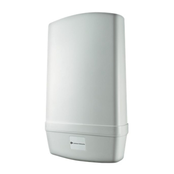
• allocated to public safety services. State and local governmental entities are eligible to hold 4.9 GHz licenses. Table 1 shows the Motorola PMP 400 Series and PTP 200 Series products available. Table 1: Products and Model Numbers Antenna Model... - Page 7 PMP 400 and PTP 200 Series Canopy User Guide Supplement Antenna Model Name Module Antenna Type included Picture Specs Number 4941APC PMP 49400 4.9 GHz OFDM AP Connectorized Figure 1 2.7.3 Figure 1: Radio (with or without integrated antenna) Figure 2: PMP 54400 AP with connectorized radio and antenna Issue 3, January 2009 Page 7 of 45...
- Page 8 Figure 3: PMP 49400 AP with connectorized radio and antenna A Canopy CMMmicro or CMM4 provides synchronization and power to the PMP 400 Series APs and PTP 200 Series BHMs. A 600SSC surge suppressor, a successor to the 300SS and 600SSB surge suppressors, provides over-voltage and over-current protection to APs, SMs, and BHs in various configurations.
- Page 9 PMP 400 and PTP 200 Series Canopy User Guide Supplement 2.1.1 NLOS and nLOS Benefits and Limitations The use of OFDM technology will help in many cases of NLOS (Non Line-of-Sight) and nLOS near Line-of-Sight (nLOS) links. LOS (Line-of-Sight ) means the installer can see the AP from the SM and the first Fresnel zone is clear.
- Page 10 PMP 400 and PTP 200 Series Canopy User Guide Supplement CONFIGURATION OPTIONS – RF, IP, DFS These systems use the Canopy Media Access Controller (MAC) layer. Settings like Downlink Data %, Range, and Control Slots are similar to Canopy FSK radios. An AP can communicate to over 200 SMs, similar to a Canopy FSK AP.
- Page 11 PMP 400 and PTP 200 Series Canopy User Guide Supplement ADMINISTRATION SYSTEMS Standard Canopy administration systems are used to support the PMP 400 and PTP 200 Series products, with the only requirement being that the administration systems must be at the appropriate release level: Prizm 3.1 is the element management system for PMP 400 and PTP 200 Series •...
-
Page 12: Table 2: Performance Details
PMP 400 and PTP 200 Series Canopy User Guide Supplement 2.7.5 System technical details Standard Canopy temperature range of -40° C to +55° C • Latency of 5-7 msec roundtrip • Products available with either DES or AES encryption • Table 2 shows performance details for the PMP 54400, PTP 54200, and PMP 49400 systems, with the standard Canopy PMP 54200 5.4 GHz FSK details shown for comparison. -
Page 13: Planning
PMP 400 and PTP 200 Series Canopy User Guide Supplement 3 Planning PMP 400 and PTP 200 Series systems use a 10 MHz channel size configurable on 5 MHz centers. This channel size, along with some different characteristics due to the use OFDM carrier technology and QPSK, 16 QAM, or 64 QAM modulation, supports somewhat different channel planning than for standard Canopy. - Page 14 PMP 400 and PTP 200 Series Canopy User Guide Supplement The best practice for channel planning for APs is to conduct extensive site RF surveys before choosing channels. For those with the equipment and expertise, use commercial and industrial spectrum analysis equipment. The PMP 400 and PTP 200 Series APs and SMs do not provide a spectrum analyzer in the first release (planned for a subsequent release), but standard 5.4 GHz FSK SMs can be used to give useful information on the RF environment in the planned PMP 400 and PTP 200 Series AP deployment location.
- Page 15 PMP 400 and PTP 200 Series Canopy User Guide Supplement Showing relative power levels across the band, to aid in selecting channels and • performing RF planning. Troubleshooting to finding the frequency, relative power level, and location of • interferers by rotating a single SM, or triangulating from multiple SMs in a geographical area.
- Page 16 PMP 400 and PTP 200 Series Canopy User Guide Supplement When collocating only Canopy OFDM APs together, or collocating only Canopy hardware- scheduled FSK APs together, the simple practice of setting the Downlink Data %, Range, and Control Slots the same on all APs ensures they won’t interfere with each other. (These parameters are set on the “Configuration =>...
-
Page 17: Configuring
PMP 400 and PTP 200 Series Canopy User Guide Supplement 4 Configuring Most Canopy Series 400 configuration items are identical or very similar to configuration items in standard FSK Canopy modules. This section discusses those that are new or changed and also remarks on some that remain unchanged. - Page 18 PMP 400 and PTP 200 Series Canopy User Guide Supplement Figure 5: Dynamic Rate Adapt on AP "Configuration => General" page In most cases, an operator is well-served to leave the setting at 1X/2X/3X and let the system automatically and dynamically choose the best rate for each link. Cases when it may be useful to lock down a link to 1X include Some aiming and alignment efforts, although usually aiming and alignment and link •...
- Page 19 AP from that SM is not greater than • 60 dBm. PMP 400 Series networks use Auto-TPC because OFDM technology is more sensitive to large differences in power levels from SMs operating at various distances from the AP than the single carrier technology used in Canopy FSK.
-
Page 20: Table 5: Control Slot Settings
PMP 400 and PTP 200 Series Canopy User Guide Supplement The default Range, set on the AP’s “Configuration => General” page, is 5 miles, but can be set in 1 mile increments between 1 and 10 miles. The BHM performs its own ranging and so no range need be set for it. -
Page 21: Table 6: Release 8.4 Operation Based On Region Code
PMP 400 and PTP 200 Series Canopy User Guide Supplement regulatory requirements drive the settings for the following parameters, as discussed in this section: Region Code • Primary Frequency • Alternate 1 and Alternate 2 Frequencies • External Antenna Gain •... - Page 22 PMP 400 and PTP 200 Series Canopy User Guide Supplement 5.4 GHz Center Channel Region Code Frequencies Available (MHz) equipment will provide DFS consistent with that regions’s regulations. For countries or regions not listed, use a Region Code that provides DFS functionality and channels consistent with your country’s regulatory requirements.
- Page 23 PMP 400 and PTP 200 Series Canopy User Guide Supplement Normal Transmit • Radar Detected Stop Transmitting for n minutes, where n counts down • from 30 to 1. Idle, only for SM or BHS, indicates module is scanning, but has not detected a •...
- Page 24 PMP 400 and PTP 200 Series Canopy User Guide Supplement Figure 6: Region Code on AP “Configuration => General” page An SM or BHS has both a configurable Region Code and, once it registers to an AP or BHM, an active Region Code.
- Page 25 PMP 400 and PTP 200 Series Canopy User Guide Supplement Figure 7: Configured Region Code on SM Configuration => General page Figure 8: Active Region Code on SM Home => General Status page The AP or BHM always operates under its manually configured Region Code (the one on the Configuration =>...
- Page 26 PMP 400 and PTP 200 Series Canopy User Guide Supplement It takes two reboots to set the parameters described below on a module starting from factory defaults. Set the Region Code as described above, “Save Changes”, and “Reboot”. If the module then invokes DFS (based on the Region Code and frequency band as shown in Table 6), the Radio Frequency Carriers and External Antenna Gain parameters will be displayed.
- Page 27 A 1/8 cyclic prefix means that for every 8 bit of throughput data transmitted, an additional bit is used. PMP 400 Series networks use a cyclic prefix of 1/4 that is not configurable by the user. PTP 200 Series modules (OFDM BHs) are settable for either 1/8 or 1/4 cyclic prefix. The use of 1/8 cyclic prefix provides about 11% higher maximum throughput, and is recommended in most cases.
- Page 28 PMP 400 and PTP 200 Series Canopy User Guide Supplement In most deployments, 1/8 Cyclic Prefix will provide a high quality, higher throughput • link. In cases with severe multi-pathing or obstructions, 1/4 Cyclic Prefix may give better overall results. Procedure for setting the Cyclic Prefix 3.
-
Page 29: Installation
This section addresses installation aspects specific to the PMP 400 and PTP 200 Series AP. General communications equipment, infrastructure, and facilities site design should be performed in line with Motorola’s “Standards and Guidelines for Communications Sites” (also known as the R56 manual), available from http://www.motorola-wls.com/Dynamic/Course_Description.asp?number=ANT001-CD&CourseKe... - Page 30 PMP 400 and PTP 200 Series Canopy User Guide Supplement Procedure 2: Assembling a 5.4 GHz AP, and attaching to tower 1. Perform a parts check to ensure all parts are present. 2. Assemble the upper bracket, per the diagram that comes with the antenna.
- Page 31 PMP 400 and PTP 200 Series Canopy User Guide Supplement 6. Use standard work and safety practices for 8. Connect the lower bracket tower climbing, and to the pole or tower, using 7. Hang the antenna assembly connect the upper on the upper bracket the quick-connect system bracket to a pole,...
- Page 32 PMP 400 and PTP 200 Series Canopy User Guide Supplement 10. Adjust downtilt as desired, per previous calculations done during Planning. If any doubts, confirm downtilt after the radio is operational using SMs in the field at selected test locations. =========================== end of procedure ====================== Procedure 3: Assembling a 4.9 GHz AP, and attaching to tower 1.
- Page 33 PMP 400 and PTP 200 Series Canopy User Guide Supplement 3. Connect the radio to the antenna by sliding it into the captive space. Secure the radio to the antenna using the two bolts provided. 4. Weatherproof the connector using standard practices, with waterproof wrap.
- Page 34 PMP 400 and PTP 200 Series Canopy User Guide Supplement can be wiped over the connector area to provide some resistance to water ingress around the connector. 3. Use a 600SSC surge suppressor within 3 ft (~1 m) of the AP, and ground it to known good ground (Protective Earth - PE) on the tower or support structure with a 10 AWG ground strap.
- Page 35 Use an SMMB2 SM mounting bracket, not an SMMB1 typically used with standard Canopy SMs. The PMP 400 Series SM or the PTP 200 Series BH is heavier and has a higher wind load than a classic Canopy module, and so the stronger SMMB2 is required. The SMMB2 is the mounting arm used with Canopy 900 MHz integrated APs and SMs, and used with reflectors.
-
Page 36: Regulatory And Legal Notices
PMP 400 and PTP 200 Series Canopy User Guide Supplement 6 Regulatory and Legal Notices IMPORTANT NOTE ON MODIFICATIONS Intentional or unintentional changes or modifications to the equipment must not be made unless under the express consent of the party responsible for compliance. Any such modifications could void the user’s authority to operate the equipment and will void the manufacturer’s warranty. -
Page 37: Table 7: Us Fcc Ids And Industry Canada Certification Numbers And Covered
PMP 400 and PTP 200 Series Canopy User Guide Supplement Table 7: US FCC IDs and Industry Canada Certification Numbers and Covered Configurations FCC ID Industry Frequencies Module Antenna Maximum Canada Cert Families Transmitter Number Output Power ABZ89FT7629 10 MHz channels, 18 dBi connectorized centered on 5480- PCTEL Model... - Page 38 This is within the 5470 to 5725 MHz U-NII band with 5600 to 5650 MHz excluded. Motorola Canopy Radio equipment operating in the 5470 to 5725 MHz band are categorized as “Class 1” devices within the EU in accordance with ECC DEC(04)08 and are “CE” marked to show compliance with the European Radio &...
- Page 39 6.2.5 EU Declaration of Conformity for RoHS Compliance Motorola hereby declares that these Motorola products are in compliance with the essential requirements and other relevant provisions of Directive 2002/95/EC, Restriction of the use of certain Hazardous Substances (RoHS) in electrical and electronic equipment.
-
Page 40: Table 8: Disclosure Table
PMP 400 and PTP 200 Series Canopy User Guide Supplement Logo 1 Logo 2 The Environmental Friendly Use Period (EFUP) is the period (in years) during which the Toxic and Hazardous Substances (T&HS) contained in the Electronic Information Product (EIP) will not leak or mutate causing environmental pollution or bodily injury from the use of the EIP. -
Page 41: Table 10: Calculated Exposure Distances And Power Compliance Margins
PMP 400 and PTP 200 Series Canopy User Guide Supplement 6.3.1 Details of Exposure Separation Distances Calculations and Power Compliance Margins Limits and guidelines for RF exposure come from: US FCC limits for the general population. See the FCC web site at •... - Page 42 Termination. This License is effective until terminated. This License will terminate immediately without notice from Motorola or judicial resolution if you fail to comply with any provision of this License. Upon such termination you must destroy the Software, all accompanying written...
- Page 43 Motorola's entire liability and your sole and exclusive remedy for any breach of the foregoing limited warranty will be, at Motorola's option, replacement of the disk(s), provision of downloadable patch or replacement code, or refund of the unused portion of your bargained for contractual benefit up to the amount paid for this Software License.
- Page 44 6.4.2 Hardware Warranty in US Motorola US offers a warranty covering a period of 1 year from the date of purchase by the customer. If a product is found defective during the warranty period, Motorola will repair or replace the product with the same or a similar model, which may be a reconditioned unit, without charge for parts or labor.
- Page 45 PMP 400 and PTP 200 Series Canopy User Guide Supplement limitation may not apply to you.) IN NO CASE SHALL MOTOROLA’S LIABILITY EXCEED THE AMOUNT YOU PAID FOR THE PRODUCT. Issue 3, January 2009 Page 45 of 45...