Table of Contents
Quick Links
Table of Contents

Related Manuals for Toshiba ST-7000 Series


Summary of Contents for Toshiba ST-7000 Series
- Page 1 TOSHIBA POS Terminal ST-7000 SERIES Owner's Manual...
- Page 2 -- Note; This is applicable to California, U.S.A only Copyright © 2004 < For EU Only > by TOSHIBA TEC CORPORATION TOSHIBA TEC Europe Retail Information Systems S.A. All Rights Reserved Rue de la Célidée 33 BE-1080 Brussels 570 Ohito, Izunokuni-shi, Shizuoka-ken, JAPAN...
- Page 3 Do not attempt to effect repairs or modifications to this equipment. If a fault occurs that cannot be rectified using the procedures described in this manual, turn off the power, unplug the machine, then contact your authorized TOSHIBA TEC representative for assistance. 0HDQLQJVRI(DFK6\PERO This symbol indicates warning items (including cautions).
- Page 4 5HTXHVW 5HJDUGLQJ 0DLQWHQDQFH Utilize our maintenance services. After purchasing the machine, contact your authorized TOSHIBA TEC representative for assistance once a year to have the inside of the machine cleaned. Otherwise, dust will build up inside the machines and may cause a fire or a malfunction. Cleaning is particularly effective before humid rainy seasons.
-
Page 5: Table Of Contents
CAUTION! 1. This manual may not be copied in whole or in part without prior written permission of TOSHIBA TEC. 2. The contents of this manual may be changed without notification. 3. Please refer to your local Authorised Service representative with regard to any queries you... -
Page 6: Introduction
1.1 Accessories 1. INTRODUCTION Thank you for choosing the TOSHIBA POS Terminal. This POS Terminal contains all the high performance register function necessary for a POS Terminal and enables the user oriented system configuration. By adopting a high-speed CPU, Memory with large capacity, this POS Terminal flexibly accepts the modification corresponding to the future system environment as the user expects. -
Page 7: Appearance
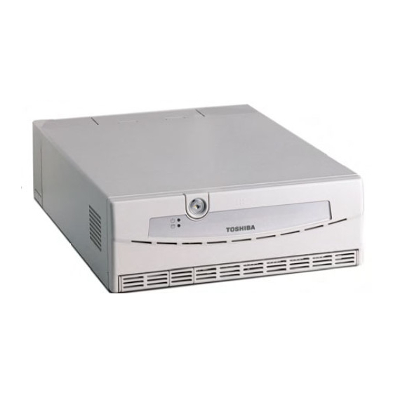
2. APPEARANCE EO1-12029 2. APPEARANCE 2. APPEARANCE < Front View > Front Panel Lock Front Panel Power LED HDD LED POWER LED Cover Catch HDD LED Reset Switch CD-RW Drive (Option) Volume Power Switch USB5 Connector (1) Power Switch This is the switch to turn the power of the POS terminal ON or OFF. The Power LED is illuminated when turning the power on. -
Page 8: Connectors
3. CONNECTORS EO1-12029 3. CONNECTORS 3. CONNECTORS COM6 (Option)* Powered USB Line-out Not Used USB0 USB1 USB2 USB3 Mic-in PCI Slot (12V-1) (12V-2) (12V-3) (24V) COM5 COM1 COM2 AC Inlet COM3 AC Outlet LPT1 24V DC Outlet COM4 Not used (5VB) PS/2 (Mouse) DVI-D, LVDS (Option) PS/2 (Keyboard) -
Page 9: Installation Procedure
4. INSTALLATION PROCEDURE EO1-12029 4.1 Environment for Installation 4. INSTALLATION PROCEDURE 4.1 Environment for Installation Provide a space of minimum 80 mm to the left, right, front, rear, and top of the main unit for proper cooling. (The main unit has air vents on the front, rear, right and left, and a fan. Spaces should be provided to prevent the air vents in the main unit from being closed and the air flow from being obstructed.) Attaching the cable cover:... -
Page 10: How To Lock/Unlock The Front Panel
5. HOW TO LOCK/UNLOCK THE FRONT PANEL EO1-12029 5. HOW TO LOCK/UNLOCK THE FRONT PANEL 5. HOW TO LOCK/UNLOCK THE FRONT PANEL << How to unlock the front panel >> Front Panel Lock Front Panel Insert the front panel key into the front panel lock, and turn it counterclockwise to unlock the front panel. -
Page 11: General Maintenance
6. GENERAL MAINTENANCE EO1-12029 6.1 Cleaning 6. GENERAL MAINTENANCE 6.1 Cleaning WARNING! 1. Be sure to disconnect the power cord prior to performing any maintenance. 2. Do not pour water directly on the POS Terminal or wipe it with a soaked cloth, as this may cause fire, electric shock, or machine failure. -
Page 12: Troubleshooting
7. TROUBLESHOOTING WARNING! If you cannot solve a problem with the following solutions, do not attempt to repair it by yourself. Turn the power off, unplug the POS Terminal, then contact the nearest TOSHIBA TEC service representative for assistance. Symptom... -
Page 13: Specifications
Power cord A power cord is not included in this product. Please use one complied with each country’s safety standard. For details, please contact the nearest TOSHIBA TEC service representative. ® Intel Celeron 2.0 GHz with 128 KB secondary cache (up to Pentium4 2.8 GHz) -
Page 14: Options
8. SPECIFICATIONS EO1-12029 8.2 Options Options Option name Type Description Drawer unit DRWST-51A-4MV-QM 24V-drive standard drawer DRWST-51A-8MV-QM Size and Weight: 460(W) x 400(D) x 115(H) mm, 10Kg Money Case Type: MC4,8 DRWST-56-EMV-QM 24V-drive flip top drawer Size and Weight: 460(W) x 170(D) x 100(H) mm, 6Kg Money Case Type: EURO case Drawer type Type... - Page 15 English Waste Recycling information for users: Following information is only for EU-member states: The crossed out wheeled bin symbol is used to indicate that the product must not be treated as general household waste. By ensuring that this product is disposed of correctly you will be helping to prevent potentially negative consequences for the environment and human health, which could otherwise be caused by incorrect waste handling of this product.
- Page 16 PRINTED IN JAPAN EO1-12029C...