
Related Manuals for Dell Precision 7920


Summary of Contents for Dell Precision 7920
- Page 1 Dell Precision 7920 Rack Owner's Manual Regulatory Model: E38S Regulatory Type: E38S001 November 2020 Rev. A02...
- Page 2 A WARNING indicates a potential for property damage, personal injury, or death. © 2018 2020 Dell Inc. or its subsidiaries. All rights reserved. Dell, EMC, and other trademarks are trademarks of Dell Inc. or its subsidiaries. Other trademarks may be trademarks of their respective owners.
-
Page 3: Table Of Contents
Contents Chapter 1: Working on your computer................... 6 Safety instructions................................6 Before working inside your computer..........................6 After working inside your computer..........................7 Chapter 2: Chassis View........................ 8 Front chassis view................................8 Back chassis view................................9 Inside the system.................................9 LCD panel.....................................10 Viewing Home screen..............................11 Setup menu.................................. - Page 4 Accessing system information by using QRL......................91 Quick Resource Locator for 7920R........................92 Chapter 5: Technology and components..................93 iDRAC9....................................93 iDRAC 9 - New features............................93 Dell Lifecycle Controller..............................94 Processors..................................95 Supported processors..............................95 Chipset....................................101 System memory................................102 General memory module installation guidelines....................103 Memory..................................
- Page 5 System battery specifications..........................126 Expansion bus specifications..........................126 Memory specifications..............................126 Ports and connectors specifications........................127 Video specifications..............................128 Environmental specifications..........................128 Chapter 7: Troubleshooting your system..................131 System diagnostics................................131 Dell Embedded System Diagnostics........................131 Chapter 8: Getting help......................133 Contacting Dell................................. 133 Contents...
-
Page 6: Chapter 1: Working On Your Computer
Damage due to servicing that is not authorized by Dell is not covered by your warranty. Read and follow the safety instructions that came with the product. -
Page 7: After Working Inside Your Computer
Steps 1. Ensure that you follow the Safety instructions. 2. Turn off the system, including any attached peripherals. 3. Disconnect the system from the electrical outlet and disconnect the peripherals. 4. If applicable, remove the system from the rack. 5. Remove the system cover. After working inside your computer About this task After you complete any replacement procedure, ensure that you connect any external devices, cards, and cables before turning... -
Page 8: Chapter 2: Chassis View
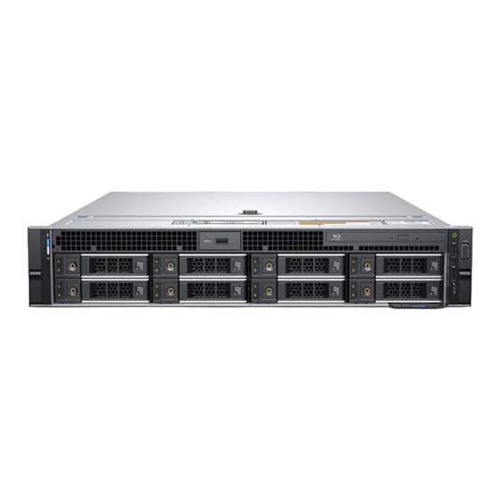
Chassis View Topics: • Front chassis view • Back chassis view • Inside the system • LCD panel Front chassis view 1. System Status Indicator 2. System health and system ID 3. iDRAC Quick Sync 2 wireless indicator 4. Hard drive (x8) 5. -
Page 9: Back Chassis View
Damage due to servicing that is not authorized by Dell is not covered by your warranty. Read and follow the safety instructions that are shipped with your product. -
Page 10: Lcd Panel
Error Code Lookup page at qrl.dell.com. The LCD panel is available only on the optional front bezel. The optional front bezel is hot pluggable. -
Page 11: Viewing Home Screen
● When the system needs attention, the LCD backlight turns amber, and displays an error code followed by descriptive text. If the system is connected to a power source and an error is detected, the LCD turns amber regardless of NOTE: whether the system is turned on or off. -
Page 12: View Menu
Option Description Select DHCP or Static IP to configure the network mode. If Static IP is selected, the available fields iDRAC are IP, Subnet (Sub), and Gateway (Gtw). Select Setup DNS to enable DNS and to view domain addresses. Two separate DNS entries are available. Select SEL to view LCD error messages in a format that matches the IPMI description in the SEL. -
Page 13: Chapter 3: Product Overview
Product Overview The following pages contain information about Dell Precision 7920 Rack product overview. Topics: • System information label System information label Precision 7920 Rack – Front system information label Figure 3. LED Behavior, Express Service Tag, Configuration and Layout Precision 7920 Rack –... -
Page 14: Chapter 4: Disassembly And Reassembly
Accessing system information by using QRL Product Positioning The Precision 7920 Rack is a general-purpose platform with highly expandable memory (up to 1536 GB), massive storage capacity and impressive I/O capability to match. The Precision 7920 Rack adds extraordinary storage capacity options, making it well-suited for data intensive applications that require greater storage, while not sacrificing I/O performance. -
Page 15: Need To Know
Table 2. Recommended tools and optional tools Recommended tools Optional tools ● Key to the system keylock ● Needle-nose pliers to disconnect cables and connectors in ● #1 and #2 Phillips screwdriver hard-to-reach locations ● Small flat-head screwdriver to disconnect small cables ●... - Page 16 ● SNMP Alert — Event can generate an SNMP trap. ● Email Alert — Event can generate an email alert. ● LC Log — Event can generate a Dell Lifecycle Controller log entry. ● LCD — Event is displayed on the system's LCD.
-
Page 17: Startup-Shutdown Sequence
Startup-Shutdown sequence Precision 7920 Rack BIOS is pure UEFI with a legacy compatibility layer. This layer is called the Compatibility NOTE: Support Module. New POST display The following are the POST display enhancements: ● The look of the boot process has been revamped for Precision 7920 Rack. - Page 18 Description Condition Corrective action ● When the is in standby. about error messages, see the Dell Event and Error Messages Reference Guide at Dell.com/ ● If any error condition exists. For openmanagemanuals > OpenManage software. example, a failed fan, PSU, or a hard drive.
-
Page 19: Hard Drive Indicator Codes
Hard drive indicator codes Each hard drive carrier has an activity LED indicator and a status LED indicator. The indicators provide information about the current status of the hard drive. The activity LED indicator indicates whether the hard drive is currently in use or not. The status LED indicator indicates the power condition of the drive. -
Page 20: Nic Indicator Codes
Drive status indicator behavior is managed by Storage Spaces Direct. Not all drive status indicators may be used. NOTE: Table 5. Hard drive indicator codes Hard drive status indicator code Condition Flashes green twice per second Identifying drive or preparing for removal. Drive ready for removal. -
Page 21: Idrac Direct Led Indicator Codes
Figure 7. AC PSU status indicator 1. AC PSU status indicator/handle Table 7. AC PSU status indicator codes Power indicator codes Condition Green A valid power source is connected to the PSU and the PSU is operational. Blinking amber Indicates a problem with the PSU. Not illuminated Power is not connected to the PSU. -
Page 22: Idrac Quick Sync 2 Indicator Codes
If the problem persists, see the Getting help section. For more information, see Integrated Dell Remote Access Controller User's Guide at dell.com/idracmanuals or Dell OpenManage Server Administrator User’s Guide at dell.com/... -
Page 23: Enhanced Preboot System Assessment
Enhanced Preboot System Assessment If you experience a problem with your system, run the system diagnostics before contacting Dell for technical assistance. The purpose of running system diagnostics is to test your system hardware without requiring more equipment or risking data loss. If you are unable to fix the problem yourself, service and support personnel can use the diagnostics results to help you solve the problem. - Page 24 7. Click OK when prompted, and the system reboots. Running the Embedded System Diagnostics from the Dell Lifecycle Controller To run the embedded system diagnostics from the Dell Lifecycle Controller: 1. As the system boots, press F10. Disassembly and reassembly...
-
Page 25: Jumpers And Connectors
2. Select Hardware Diagnostics → Run Hardware Diagnostics. Jumpers and connectors This topic provides specific information about the jumpers. It also provides some basic information about jumpers and switches and describes the connectors on the various boards in the system. Jumpers on the system board help to disable the system and setup passwords. -
Page 26: System Board Jumpers And Connectors
System board jumpers and connectors Figure 12. System board jumpers and connectors Table 10. System board jumpers and connectors Item Connector Description J_ODD Optical drive power connector A7, A1, A8, A2, A9, A3 Memory module sockets J_FAN2U_6 Cooling fan 6 connector J_BP3 Backplane 3 power connector J_FAN2U_5... -
Page 27: System Board Jumper Settings
Table 10. System board jumpers and connectors Item Connector Description J_BP_SIG1 Backplane 1 signal connector B6, B12, B5, B11, B4, B10 Memory module sockets J_BP1 Backplane 1 power connector J_FAN2U_1 Cooling fan 1 connector P_LFT_CP Left control panel connector CPU2 CPU2 processor and heat sink module socket (with dust cover) J_R3_X24... -
Page 28: Disabling Forgotten Password
Damage due to servicing that is not authorized by Dell is not covered by your warranty. Read and follow the safety instructions that are shipped with your product. -
Page 29: System Cover
The bezel key is attached to the LCD bezel package. NOTE: 2. Unlock the bezel by using the key. 3. Press the release button to release the bezel, and pull the left end of the bezel. 4. Unhook the right end, and remove the bezel. Installing the optional front bezel Steps 1. -
Page 30: Optical Drive
2. Lift the latch till the system cover slides back and the tabs on the system cover disengage from the slots on the system. 3. Hold the cover on both sides, and lift the cover away from the system. Installing system cover Prerequisites 1. -
Page 31: Air Shroud
Next steps Install the optical drive. Installing optical drive Steps 1. Slide the optical drive to the system, until the locks into place. 2. Connect the optical drive cable on the optical drive. 3. Install system cover and front bezel if applicable. Air shroud Removing air shroud Prerequisites... -
Page 32: Cooling Fan Assembly
Next steps Install the shroud. Installing air shroud Prerequisites 1. If applicable, route the cables inside the system along the system wall and secure the cables by using the cable securing bracket. Steps 1. Align the tabs on the air shroud with the slots on the system. 2. -
Page 33: Cooling Fans
Installing cooling fan assembly Steps 1. Align the guide rails on the cooling fan assembly with the standoffs on the system. 2. Lower the cooling fan assembly into the system until the cooling fan connectors engage with the connectors on the system board. -
Page 34: Intrusion Switch
Installing cooling fan Steps 1. Holding the release tab, align the connector at the base of the cooling fan with the connector on the system board. 2. Slide the cooling fan into the cooling fan assembly until the release tab locks into place. Intrusion switch Removing intrusion switch Prerequisites... -
Page 35: Hard Drive
Installing intrusion switch Steps 1. Align the tabs on the intrusion switch with the slots on the cooling fan assembly. 2. Pull the intrusion switch up and push it until the switch locks in place. Next steps 1. Install the cooling fan assembly. Hard drive Removing hard drive blank Prerequisites... - Page 36 Installing hard drive blank Steps Insert the hard drive blank into the hard drive slot and push until the release button clicks into place. Next steps 1. If removed, install the front bezel. Removing hard drive Prerequisites 1. If applicable, remove the front bezel. 2.
- Page 37 Next steps Install the hard drive. If you are not replacing the hard drive immediately, insert a hard drive blank in the empty hard drive slot. NOTE: Installing hard drive Prerequisites CAUTION: When installing a hard drive, ensure that the adjacent drives are fully installed. Inserting a hard drive carrier and attempting to lock its handle next to a partially installed carrier can damage the partially installed carrier's shield spring and make it unusable.
- Page 38 Figure 13. Installing hard drive Next steps If applicable, install the front bezel. Removing 3.5 inch hard drive from hard drive carrier Steps 1. Using Phillips #1 screwdriver, remove the screws from the slide rails on the hard drive carrier. 2.
- Page 39 Installing 3.5 inch hard drive into hard drive carrier Steps 1. Insert the hard drive into the hard drive carrier with the connector end of the hard drive toward the back of the carrier. 2. Align the screw holes on the hard drive with the screws holes on the hard drive carrier. When aligned correctly, the back of the hard drive is flush with the back of the hard drive carrier.
- Page 40 Next steps Install the hard drive. If you are not replacing the hard drive immediately, insert a hard drive blank in the empty hard drive slot. NOTE: Installing 2.5 inch hard drive Prerequisites CAUTION: When installing a hard drive, ensure that the adjacent drives are fully installed. Inserting a hard drive carrier and attempting to lock its handle next to a partially installed carrier can damage the partially installed carrier's shield spring and make it unusable.
- Page 41 Figure 14. Installing hard drive Next steps If applicable, install the front bezel. Removing 2.5 inch hard drive from 3.5 inch hard drive carrier Steps 1. Using Phillips #1 screwdriver, remove the screws from the slide rails on the 3.5 inch hard drive carrier and lift the hard drive. Disassembly and reassembly...
- Page 42 2. Remove the screws that secures 2.5 inch hard drive to the hard drive assembly and remove the hard drive. Next steps Install hard drive into the hard drive carrier. Installing 2.5 inch hard drive into 3.5 inch hard drive carrier Steps 1.
-
Page 43: Memory Modules
2. Place the 2.5 inch hard drive into the 3.5 inch hard drive carrier. 3. Align the screw holes on the hard drive with the screws holes on the hard drive carrier. Memory modules Removing memory modules Prerequisites 1. If applicable, remove the air shroud. WARNING: Allow the memory modules to cool after you power off the system. - Page 44 CAUTION: To ensure proper system cooling, memory module blanks must be installed in any memory socket that is not occupied. Remove memory module blanks only if you intend to install memory modules in those sockets. Steps 1. Locate the appropriate memory module socket. 2.
-
Page 45: Processors And Heat Sinks
Processors and heat sinks Removing processor and heat sink module Steps 1. Using Torx #T30 screwdriver, loosen the screws. Ensure that the screw is completely loosened before moving on to the next screw. NOTE: 2. Pushing both retention clips simultaneously, lift the processor heat sink module out of the system 3. - Page 46 4. Lift the bracket and the processor away from the heat sink, and place the processor connector side down on the processor tray. 5. Flex the outer edges of the bracket to release the processor from the bracket. Ensure that the processor and the bracket are placed in the tray after you remove the heat sink. NOTE: Installing processor into processor heat sink module Steps...
- Page 47 Figure 16. Installing the processor bracket 3. If you are using an existing heat sink, remove the thermal grease from the heat sink by using a clean lint-free cloth. 4. Use the thermal grease syringe included with your processor kit to apply the grease in a spiral quadrilateral design on the top of the processor.
- Page 48 NOTE: ● Ensure that the two guide pin holes on the bracket match the guide holes on the heat sink. Next steps 1. Install the processor and heat sink module. 2. Install air shroud. Installing processor and heat sink module Steps 1.
-
Page 49: Expansion Card
Figure 18. Installing the processor and heat sink module (2U) Expansion card Removing expansion card from expansion card riser Prerequisites 1. If applicable, disconnect the cables from the expansion card. Steps 1. Lift the expansion card latch out of the slot. 2. - Page 50 Figure 20. Removing expansion card from expansion card riser 2 Figure 21. Removing expansion card from expansion card riser 3 3. If you are removing the card permanently, install a metal filler bracket over the empty expansion slot opening and close the expansion card latch.
- Page 51 Installing expansion card into expansion card riser Prerequisites 1. Unpack the expansion card and prepare it for installation. For instructions, see the documentation accompanying the card. NOTE: Steps 1. Lift the expansion card latch and remove the filler bracket. 2. Hold the card by its edges, and align the card edge connector with the expansion card connector on the riser. 3.
- Page 52 About this task If installing a replacement expansion card riser 1 make sure the VROC key is transfered from the old card to the new NOTE: card. Disassembly and reassembly...
- Page 53 Steps 1. Pull the expansion card latch out of the slot. 2. Hold the expansion card by its edges, and pull the card until the card edge connector disengages from the expansion card connector on the riser. Figure 22. Removing expansion card riser 1 Installing expansion card riser 1 About this task If installing a replacement expansion card riser 1 make sure the VROC key is transfered from the old card to the new...
- Page 54 Steps 1. Align the guide rails on the riser with the standoffs on the side of the system. 2. Lower the riser into the system until the riser card connector engages with the connector on the system board. Next steps 1.
- Page 55 Next steps 1. If removed, install expansion cards into the riser and connect any cable disconnected. 2. If applicable, install the air shroud. If applicable, open the PCIe card holder latch on the air shroud to install the full length card. NOTE: 3.
-
Page 56: Vflash Card - Optional
Next steps 1. If removed, install expansion cards into the riser and connect any cable disconnected. 2. If applicable, install the air shroud. If applicable, open the PCIe card holder latch on the air shroud to install the full length card. NOTE: 3. -
Page 57: Network Daughter Card
Network daughter card Removing network daughter card Prerequisites 1. Remove the expansion card riser 2. Steps 1. Using a Phillips #2 screwdriver, loosen the captive screws that secure the Network Daughter Card (NDC) to the system board. 2. Hold the NDC by the edges on either side of the touch points and lift to remove it from the connector on the system board. 3. -
Page 58: Front Usb Module
CAUTION: Note the number of each hard drive and temporarily label them before you remove the hard drive so that you can replace them in the same locations. 1. Remove the air shroud. 2. Remove the cooling fan assembly. 3. Remove the backplane cover. 4. -
Page 59: Internal Usb Memory Key (Optional)
2. Remove the system cover. Steps 1. Unroute the cable and remove the screw that secures the USB module on the system. 2. Push the cable and disconnect it from the system. 3. Remove the front USB module from the system. Installing front USB module Steps 1. -
Page 60: Power Supply Unit
Power supply unit Removing power supply unit blank Install the power supply unit (PSU) blank only in the second PSU bay. Steps If you are installing a second PSU, remove the PSU blank in the bay by pulling the blank outward. CAUTION: To ensure proper system cooling, the PSU blank must be installed in the second PSU bay in a non-redundant configuration. -
Page 61: System Board
Installing AC power supply unit Steps Slide the PSU into the system until the PSU is fully seated and the release latch snaps into place. Next steps 1. Connect the power cable to the PSU, and plug the cable into a power outlet. CAUTION: When connecting the power cable to the PSU, secure the cable to the PSU with the strap. - Page 62 h. Internal USB key (if installed) Processor and heat sink module Processors and memory blank CAUTION: To prevent damage to the processor pins when replacing a faulty system board, ensure that you cover the processor socket with the processor protective cap. k.
-
Page 63: Trusted Platform Module
Service Tag page. Other configuration issues must also be done manually, for instance importing iDRAC License through iDRAC GUI 5. Import your new or existing iDRAC Enterprise license. For more information, see Integrated Dell Remote Access Controller User's Guide, at Dell.com/esmmanuals. -
Page 64: Control Panel
Figure 26. Installing the TPM Next steps 1. Install the system board. Initializing TPM for BitLocker users Steps Initialize the TPM. For more information, see https://technet.microsoft.com/library/cc753140.aspx. The TPM Status changes to Enabled, Activated. Initializing the TPM 1.2 for TXT users Steps 1. - Page 65 3. Holding the control panel and cable tube by its sides, remove the control panel and cable tube away from the system. Installing left control panel Steps 1. Route the control panel cable through the side wall of the system. 2.
-
Page 66: Gpu Host Card Installation
Installing right control panel Steps 1. Route the control panel cable and VGA cable through the side wall of the system. 2. Align the control panel with the control panel slot on the system and attach the control panel to the system. 3. - Page 67 To install the alternate riser, complete the following steps: 1. Remove any existing risers and GPU power cables from the chassis in slot 3. 2. Insert and firmly press the alternate riser 3 into the appropriate slot on the motherboard until it is seated properly. Disassembly and reassembly...
-
Page 68: Teradici Tera2220 Host Cards Installation
This section describes the installation of Teradici host cards into the system. The host cards should have the low-profile PCI card brackets installed to fit into riser 1 on the Dell Precision Rack 7910. To install the host card, complete the following steps: 1. - Page 69 3. Open the retention clip for the low-profile PCI cards. 4. Install the three Teradici host cards into their respective PCIe slots. 5. Make sure the cards are sitting flush, and press the retaining bracket and the support bracket back into place. Disassembly and reassembly...
- Page 70 6. Install the host card's power button cables into the rear of the Teradici host cards. The image below shows the rear of the low-profile module and host cards Disassembly and reassembly...
- Page 71 7. Install the low-profile module back into the chassis in slot 1. Make sure the power button cables are not pinched between the module and the chassis case. Disassembly and reassembly...
- Page 72 8. Make sure the module is aligned correctly and press down firmly to seat it in the slot. 9. Remove the CPU air baffle from the chassis. Disassembly and reassembly...
-
Page 73: Nvidia Quadro K4200 Graphics Cards Installation
10. Route the power button cable from the closest Teradici host card as shown below, and insert the 2-pin female receptacle into P34 on the motherboard. 11. Daisy-chain the remaining connectors by connecting the 2-pin female connector on the additional cables to the male connector on the previous cable. - Page 74 The host cards should have the low-profile PCI card brackets installed to fit into riser 1 on the Dell Precision Rack 7910. To install the graphics cards, complete the following steps: Disassembly and reassembly...
- Page 75 1. Install the GPU power cables into risers 2 and 3 as shown below. Disassembly and reassembly...
- Page 76 2. Connect one of the 6-pin power connectors to the first GPU and install the GPU into the bottom slot on riser 2. 3. Connect the second 6-pin connector on the same power lead to the second card and install it into the top slot on riser 2. Disassembly and reassembly...
- Page 77 4. Press down the PCI retention mechanism and supporting clips. 5. Connect a 6-pin connector from the power lead to the third card and install it into the top slot on riser Disassembly and reassembly...
-
Page 78: Cabling Teradici Host Cards To Gpus
6. Press down the PCI retention mechanism and supporting clips. 7. The back of the system should now look like the below diagram with slots 1-6 populated with PCI cards. Cabling Teradici Host Cards to GPUs This section outlines the installation of mini-DisplayPort (mDP)-to-DisplayPort (DP) cables for the Teradici host cards into the system. - Page 79 Table 12. Cabling Teradici Host cards Teradici 2220 Host Card NVIDIA Quadro K4200 PCI Slot 1 PCI Slot 4 <-> PCI Slot 2 PCI Slot 5 <-> PCI Slot 3 PCI Slot 6 <-> For cable installation, complete the following steps: 1.
- Page 80 2. Connect the mDP-to-DP cables from port 3 on the GPUs to port 2 on the Teradici host cards as shown below. 3. Ensure all cables are firmly seated, and tidy them up if desired. 4. The system is now ready for setup and configuration. Disassembly and reassembly...
-
Page 81: Updating Bios
NOTE: service tag. Once the service tag is entered, it cannot be updated or changed. 5. Click OK. Installation Installing the Precision 7920 Rack requires information about the following topics: ● Rack Rails ● System Initialization ● Basic Configuration Disassembly and reassembly... -
Page 82: Rack Rails
Rack Rails The rail offerings consist of two types of rails — sliding and static. The sliding rails allow the system to be fully extended out of the rack for service. They are available with or without the optional cable management arm (CMA). The static rails support a wider variety of racks than the sliding rails. - Page 83 Table 13. Sliding and Static Rails Rail Mounting Rail type Supported rack types identi interface 4-Post 2-Post fier Square Round Thread Flush Center Ready Rails II Sliding √ √ √ Ready Rails Static √ √ √ √ √ Screws are not included in either kit due to the fact that threaded racks are offered with a variety of thread NOTE: designations.
- Page 84 Rack Installation The 2U system requires two people for installation due to its heavier weight. NOTE: Installing the system into the rack (option A: Drop-In) The sliding rails are a "drop-in" design. This means that the system is installed vertically into the rails by inserting the standoffs on the sides of the system into the "J-slots"...
- Page 85 Figure 28. Rail standoffs seated in J-slots 4. Push the system inward until the lock levers click into place 5. Pull the blue slide release lock tabs forward on both rails and slide the system into the rack until the system is in the rack. Disassembly and reassembly...
- Page 86 Figure 29. Slide system into the rack Installing the system into the rack (option B: Stab-In) The static rails are a "stab-in" design. This means that the inner (chassis) rail members must first be attached to the sides of the system and then inserted into the outer (cabinet) members installed in the rack.
- Page 87 Figure 30. Pull out the intermediate rail Table 15. Rail component Rail component Intermediate rail Inner rail 3. Attach the inner rails to the sides of the system by aligning the J-slots on the rail with the standoffs on the system and sliding forward on the system until they lock into place.
- Page 88 Figure 31. Attach the inner rails to the system 4. With the intermediate rails extended, install the system into the extended rails. Disassembly and reassembly...
- Page 89 Figure 32. Install system into the extended rails 5. Pull the blue slide release lock tabs forward on both the rails ,and slide the system into the rack. Figure 33. Slide system into the rack Disassembly and reassembly...
-
Page 90: Initialization
● Power on the attached peripherals. Methods of setting up and configuring the iDRAC IP address You can set up the Integrated Dell Remote Access Controller (iDRAC) IP address by using one of the following interfaces: 1. iDRAC Settings utility 2. -
Page 91: Basic Configuration
If you do not have the service tag, select Automatically detect my Service Tag for me to allow the system NOTE: to automatically detect your service tag, or select Choose from a list of all Dell products to select your product from the Product Selection page. -
Page 92: Quick Resource Locator For 7920R
Steps 1. Go to Dell.com/QRL and navigate to your specific product or 2. Use your smartphone or tablet to scan the model-specific Quick Resource (QR) code on your Dell system or in the Quick Resource Locator section. Quick Resource Locator for 7920R... -
Page 93: Chapter 5: Technology And Components
The Integrated Dell Remote Access Controller (iDRAC) is designed to make system administrators more productive and improve the overall availability of Dell system. iDRAC alerts administrators to system issues, helps them perform remote system management, and reduces the need for physical access to the system. -
Page 94: Dell Lifecycle Controller
● iDRAC Direct USB on the front of the system is now a Micro B slot, and is hard wired to iDRAC only for increased security. ● Added new System Lockdown feature to restrict use of Dell tools to make changes to BIOS, iDRAC, firmware, etc. -
Page 95: Processors
Processors The Precision 7920 Rack systems feature the Intel Xeon scalable processor family(Skylake-SP) offers versatility across diverse workloads. These processors are designed for next-generation data centers running on, software defined infrastructure supercharged for efficiency, performance, and agile services delivery across cloud-native and traditional applications. The Intel Xeon scalable processor family support workloads for cloud, high-performance computing, networking, and also storage for data centers. - Page 96 Table 16. Supported Processors for Precision 7920 Rack Model Intel Dell DPN Speed(G Cache(M QPI(GT/s Cores Turbo type Memor Speed( MT/s) Intel 3104 Bronze JNFW5 19.25 2133 No Turbo Xeon Scalable Processo Intel 6148 Gold MXCY0 27.5 10.4 2400 Turbo...
- Page 97 Table 16. Supported Processors for Precision 7920 Rack Model Intel Dell DPN Speed(G Cache(M QPI(GT/s Cores Turbo type Memor Speed( MT/s) Intel 5122 Gold 6JMR6 16.5 10.4 2400 Turbo 105W Xeon Scalable Processo Intel 6152 Gold Y1HH1 30.25 10.4 2400...
- Page 98 Table 16. Supported Processors for Precision 7920 Rack Model Intel Dell DPN Speed(G Cache(M QPI(GT/s Cores Turbo type Memor Speed( MT/s) Intel 8156 Platinum HV7Y2 16.5 10.4 2666 Turbo 105W Xeon Scalable Processo Intel 8176 Platinum 35TP4 10.4 2666 Turbo...
- Page 99 Table 16. Supported Processors for Precision 7920 Rack (continued) Model Intel Dell DPN Speed(G Cache(M QPI(GT/s Cores Turbo type Memor Speed( MT/s) Intel 3204 Gold MTH64 8.25 2133 No Turbo Xeon processo Intel 4208 Silver G1M20 2.10 2400 Turbo Xeon...
- Page 100 Table 16. Supported Processors for Precision 7920 Rack (continued) Model Intel Dell DPN Speed(G Cache(M QPI(GT/s Cores Turbo type Memor Speed( MT/s) processo Intel 6230 Gold 95XN2 27.5 10.4 2933 Turbo 125W Xeon processo Intel 6240 Gold T5T3W 2.16 24.75 10.4...
-
Page 101: Chipset
Single CPU Configuration The Precision 7920 Rack will function normally if there is just a single processor placed in the CPU1 socket . However, CPU and memory blank associated with CPU2 are required to be populated for thermal reasons. The system will not boot if only CPU2 socket is populated. -
Page 102: System Memory
● PCI Express* Base Specification Revision 3.0 ● Integrated Serial ATA host controller, supports data transfer rates of up to 6 Gb/s on all ports. ● xHCI USB controller with SuperSpeed USB 3.0 ports ● Direct Media Interface ● Serial Peripheral Interface ●... -
Page 103: General Memory Module Installation Guidelines
● Populate six memory modules per processor (one DIMM per channel) at a time to maximize performance. Memory The Precision 7920 Rack supports up to 24 DIMMs, with up to 1536GB of memory and speeds of up to 2666MT/s. Technology and components... -
Page 104: Lcd Panel
Memory Speed The Precision 7920 Rack supports memory speeds of 2666 MT/s, 2400 MT/s, and 2133 MT/s depending on the DIMM types installed and the configuration. All memory on all processors and channels run at the same speed and voltage. By default, this speed will be the highest speed supported by the CPU and the DIMMs. -
Page 105: Viewing Home Screen
Error Code Lookup page at qrl.dell.com. The LCD panel is available only on the optional front bezel. The optional front bezel is hot pluggable. -
Page 106: Setup Menu
Setup menu When you select an option in the Setup menu, you must confirm the option before proceeding to the next action. NOTE: Option Description Select DHCP or Static IP to configure the network mode. If Static IP is selected, the available fields iDRAC are IP, Subnet (Sub), and Gateway (Gtw). - Page 107 Table 23. Expansion card riser specifications Expansion card PCIe slots on Processor Height Length Link Slot width riser the riser connection Riser 2A Slot 5 Processor 2 Full Height Full Length Riser 2A Slot 6 Processor 1 Low Profile Half Length Riser 3A Slot 7 Processor 2...
-
Page 108: Storage
8. No Teradici P25 or P45 in slot 3 Storage The Precision 7920 Rack provide scalable storage that allows you to adapt to your workload and operational demands. The Precision 7920 Rack offers storage expansion with the front hard drive cage. -
Page 109: Hot Spare Feature
You can configure the hot spare feature by using the iDRAC settings. For more information, see the iDRAC User’s Guide available at Dell.com/idracmanuals. Trusted platform module The Trusted Platform Module (TPM) is used to generate and store keys, protect or authenticate passwords, and create and store digital certificates. - Page 110 ● TPM TPM 2.0 Nuvoton FIPS-CC-TCG ● TPM 2.0 NationZ In a scenario where both the control panel and system board are dispatched, Dell recommends you to replace the NOTE: control panel first and try to turn on the system to complete the Easy Restore process (Service Tag, licenses, copy to the new control panel).
-
Page 111: Chapter 6: Bios And Uefi
By using the System Setup screen, you can configure the BIOS settings, iDRAC settings, and device settings of your system. These settings have already been preconfigured per solution requirements. Contact Dell before you change these settings. Help text for the selected field is displayed in the graphical browser by default. To view the help text in the text NOTE: browser, press F1. -
Page 112: System Setup Main Menu
The iDRAC Settings utility is an interface to set up and configure the iDRAC parameters using UEFI. You can enable or disable various iDRAC parameters by using the iDRAC Settings utility. For more information about this utility, see the Integrated Dell Remote Access Controller User’s Guide at dell.com/ esmmanuals. -
Page 113: System Information Screen Details
System information screen details You can use the System Information screen allows to view system properties such as Service Tag, system model, and BIOS version. About this task You can view the System Information screen by clicking System Setup Main Menu > System BIOS > System Information. -
Page 114: Processor Settings Screen Details
NOTE: the memory configuration of your system. The Dell Fault Resilient Mode establishes an area of memory that is fault resilient. This NOTE: mode can be used by an operating system that supports the feature to load critical applications or enables the operating system kernel to maximize system availability. -
Page 115: Sata Settings Screen Details
Menu Item Description Dell Controlled Depending on the number of installed CPUs, there may be up to four processor listings. NOTE: Turbo Controls the turbo engagement. Enable this option only when System Profile is set to Performance. Controls the number of enabled cores in each processor. By default, the Number of Cores per Number of Cores Processor option is set to All. - Page 116 Menu Item Description Displays the type of drive attached to the SATA port. Drive Type Displays the total capacity of the hard drive. The field is undefined for removable media devices such as Capacity optical drives. Sets the drive type of the selected device. Port C Displays the drive model of the selected device.
-
Page 117: Boot Settings Screen Details
Menu Item Description Displays the type of drive attached to the SATA port. Drive Type Displays the total capacity of the hard drive. The field is undefined for removable media devices such as Capacity optical drives. Displays the total capacity of the hard drive. The field is undefined for removable media devices such as Capacity optical drives. -
Page 118: Network Settings Screen Details
Menu Item Description This field enables or disables the boot option in UEFI Boot Sequence. Boot option Enable/Disable Network settings screen details You can use the Network Settings screen to set the Boot mode from UEFI. It also allows you to specify the boot order. About this task You can view the Network Settings screen by clicking System Setup Main Menu >... -
Page 119: Integrated Devices Screen Details
Integrated devices screen details You can use the Integrated Devices screen to view and configure the settings of all integrated devices including the video controller, integrated RAID controller, and the USB ports. About this task You can view the Integrated Devices screen by clicking System Setup Main Menu > System BIOS > Integrated Devices. The Integrated Devices screen details are explained below. - Page 120 Menu Item Description Slot Disablement Enables or disables the available PCIe slots on your system. The Slot Disablement feature controls the configuration of PCIe cards installed in the specified slot. Slot disablement must be used only when the installed peripheral card is preventing booting into the operating system or causing delays in system startup.
-
Page 121: Serial Communication Screen Details
Serial Communication screen details You can use the Serial Communication screen to view the properties of the serial communication port. About this task You can view the Serial Communication screen by clicking System Setup Main Menu > System BIOS > Serial Communication. -
Page 122: System Security Settings Screen Details
Menu Item Description Enables or disables the Energy Efficient Turbo. Energy Efficient Turbo Energy Efficient Turbo (EET) is a mode of operation where a processor’s core frequency is adjusted within the turbo range based on workload. Enables or disables the processor to switch to a minimum performance state when it is idle. By default, the C1E option is set to Disabled. - Page 123 The System Security Settings screen details are explained as follows: Menu Item Description Improves the speed of applications by performing encryption and decryption using the Advanced Intel AES-NI Encryption Standard Instruction Set and is set to Enabled by default. Sets the system password. This option is set to Enabled by default and is read-only if the password System jumper is not installed in the system.
-
Page 124: Miscellaneous Settings Screen Details
This field is only for UEFI boot mode. You cannot set this to Enabled if UEFI Secure Boot mode is enabled. This option is enabled by default. Dell Wyse P25BIOS Access Specifies how the system reacts when system transitions to S5 state and is set to None. -
Page 125: Chassis Weight
Maximum weight (with all hard drives/SSDs) 3.5 inch hard drive systems 28.6 kg (63.05 lb) Processor specifications The Precision 7920 Rack system supports the following processors: ● Intel Xeon E5-26xx v5 processor ● Intel Xeon E5-26xx v6 processor ● Intel Xeon Gold 52xx processors ●... -
Page 126: Psu Specifications
Expansion bus specifications The Precision 7920 Rack system supports up to eight PCI express (PCIe) generation 3 expansion cards, that can be installed on the system board using expansion card risers. The following table provides detailed information about the expansion card riser specifications: Table 30. -
Page 127: Ports And Connectors Specifications
NOTE: VGA ports The Video Graphic Array (VGA) port enables you to connect the system to a VGA display. The Precision 7920 Rack system supports two 15-pin VGA ports on the front and back panels. Serial connector The Precision 7920 Rack system supports one serial connector on the back panel, which is a 9-pin connector, Data Terminal Equipment (DTE), 16550-compliant. -
Page 128: Video Specifications
Video specifications The Precision 7920 Rack system supports integrated Matrox G200eW3 graphics controller with 16 MB of video frame buffer. Table 32. Supported video resolution options Resolution Refresh rate (Hz) Color depth (bits) 1024 x 768 8, 16, 32 1280 x 800... - Page 129 Table 36. Maximum shock specifications Maximum shock Specifications Operating Six consecutively executed shock pulses in the positive and negative x, y, and z axes of 6 G for up to 11 ms. Storage Six consecutively executed shock pulses in the positive and negative x, y, and z axes (one pulse on each side of the system) of 71 G for up to 2 ms.
- Page 130 Table 40. Gaseous contamination specifications Gaseous contamination Specifications Copper coupon corrosion rate <300 Å/month per Class G1 as defined by ANSI/ISA71.04-2013. Silver coupon corrosion rate <200 Å/month as defined by ANSI/ISA71.04-2013. Maximum corrosive contaminant levels measured at ≤50% relative humidity. NOTE: BIOS and UEFI...
-
Page 131: Chapter 7: Troubleshooting Your System
Damage due to servicing that is not authorized by Dell is not covered by your warranty. Read and follow the safety instructions that are shipped with your product. - Page 132 Running the Embedded System Diagnostics from the Dell Lifecycle Controller Steps 1. As the system boots, press F10. 2. Select Hardware Diagnostics → Run Hardware Diagnostics. The ePSA Pre-boot System Assessment window is displayed, listing all devices detected in the system. The diagnostics starts executing the tests on all the detected devices.
-
Page 133: Chapter 8: Getting Help
About this task Dell provides several online and telephone-based support and service options. Availability varies by country and product, and some services may not be available in your area. To contact Dell for sales, technical support, or customer service issues: Steps 1.