Table of Contents
Quick Links
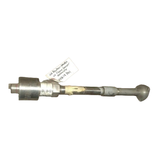
Flame Tracker*
SiC Two Wire Flame Sensor
Reuter-Stokes
Model RS-FS-9006
GE 07482SOCNL44819P01
Operation and Maintenance Manual
FS-9006OM Rev. K
November 2017
www.gemeasurement.com
* A trademark of Baker Hughes, a GE company, LLC
©2017 Baker Hughes, a GE company. All rights reserved.
Technical content subject to change without notice.
Table of Contents

Summary of Contents for GE Baker Hughes Reuter-Stokes Flame Tracker RS-FS-9006
- Page 1 Model RS-FS-9006 GE 07482SOCNL44819P01 Operation and Maintenance Manual FS-9006OM Rev. K November 2017 www.gemeasurement.com * A trademark of Baker Hughes, a GE company, LLC ©2017 Baker Hughes, a GE company. All rights reserved. Technical content subject to change without notice.
- Page 2 OTHERWISE. THIS DISCLAIMER APPLIES, WITHOUT LIMITATION, TO ANY DAMAGES OR INJURY ARISING FROM ANY FAILURE OF PERFORMANCE, ERROR, OMISSION, YOUR LOSS OF PROFITS, DESTRUCTION, AND ANY OTHER TANGIBLE OR INTANGIBLE LOSS. Copyright © 2017 Baker Hughes, a GE company. Contains Baker Hughes, a GE company Confidential Information.
- Page 3 FS-9006OM – REV K Revision History REV#: G ECN#: WRTR: DATE: 7233394 K. Schmidt 10/2006 REV#: D ECN#: WRTR: DATE: 7233394 L. Lombardo 10/12/2009 REV#: E ECN#: WRTR: DATE: 40293054 R. Martin 06/25/10 REV#: F ECN#: WRTR: DATE: 77469075 J. Hashmi 04/24/13 REV#: G ECN#:...
- Page 4 Brazil INMETRO Taiwan hazardous hazardous area mark area mark These certifications are based on the use of approved interconnecting cables only. Currently available approved interconnecting cables are BHGE Reuter-Stokes RS-E2-0285PXXX and GE 362A1053PXXX. See Section 1.1.2 for details.
- Page 5 Certifications are based on the use of approved cables only. Currently available approved cables are BHGE Reuter- Stokes RS-E2-0279 and GE AE 07482SOCNL44820. Do not attempt to disassemble the sensor. Sensors are not repairable. Breaching the seal of the sensor will cause loss of the inert fill gas and render the sensor unusable.
-
Page 6: Table Of Contents
FS-9006OM – REV K TABLE OF CONTENTS INTRODUCTION ..............................1 1.1 SPECIFICATIONS ..............................1 1.1.1 Flame Tracker™ -RS-FS-9006 ........................1 1.1.2 INTERCONNECTING CABLE RS-E2-0279PXXX OR 362A1053PXXX .............2 1.2 REFERENCE..............................3 1.3 GENERAL DESCRIPTION ..........................4 SENSOR ................................4 INSTALLATION ..............................5 3.1 MECHANICAL ..............................5 3.2 ELECTRICAL..............................7 3.3 CONNECTOR PINOUT ............................8 3.4 SENSOR CHECKOUT ............................8... -
Page 7: Introduction
FS-9006OM – REV K INTRODUCTION 1.1 SPECIFICATIONS 1.1.1 Flame Tracker™ -RS-FS-9006 Mechanical Body Mount: AISI316 Stainless Steel Housing: AISI304 Stainless Steel (sealed and Argon filled) Connector 3/4” NPT female Process: Electrical: MIL-C-38999 Series III size 15 (5 pin) Sensor: Silicon Carbide photodiode Window: Sapphire Operating... -
Page 8: Interconnecting Cable Rs-E2-0279Pxxx Or 362A1053Pxxx
FS-9006OM – REV K 1.1.2 INTERCONNECTING CABLE RS-E2-0279PXXX OR 362A1053PXXX Mechanical Wire 18 gauge (1.02 mm), 19 strand nickel plated copper Insulation Teflon PTFE Shield 36 gauge (0.127 mm) nickel plated copper braid Jacket Extruded PFA Armor Stainless steel braid Connector MIL-C-38999 series III, shell size 15, 5 #16 pins (only 3 pins are used) -
Page 9: Reference
FS-9006OM – REV K 1.2 REFERENCE... -
Page 10: General Description
Geiger Mueller tube based flame detectors is absorbed by the fog of fuel, steam or water. GE’s research center invented a silicon carbide (SiC) photodiode that is significantly more sensitive to the longer wavelength components of the UV light generated by the flame. This longer wavelength light does penetrate the fog of oil quite well and therefore the SiC based sensor is significantly more sensitive to the presence of flame. -
Page 11: Installation
Air cooling with pressurized air requires the use of Air Cooling Can BHGE Reuter-Stokes Part Number RS- E2-0259 (GE Part Number 07482SOCNL44821P01). The Air-Cooing Can is installed as shown in the following drawing. The Air-Cooling Can requires 25 psi (170 kPa) minimum at 120° F (49° C) maximum. Under these conditions the sensors will operate at ambient temperatures up to 302°... - Page 12 FS-9006OM – REV K 1. Ensure that the cooling coil is not attached to the flame sensor during installation or removal of the sensor. The cooling coil can apply an unwanted torque and cause disassembly and malfunction of the flame sensor. 2.
-
Page 13: Electrical
FS-9006OM – REV K 3.2 ELECTRICAL The sensors are connected to the turbine junction box with a connector cable as specified in Section 1.1. All wiring must be in grounded conduit or armored. The green wire must be connected to earth ground at the junction box. -
Page 14: Connector Pinout
The Flame Sensor provides a minimum output of 5 milliamps when exposed to the minimum flame intensity specified in GE specification number 362A1052. The set point for flame off should be set to 6.25%, which is equal to 5 milliamps. The set point for flame on should be 10% of full scale, which equals 5.6 milliamps. If the intensity levels are too low for these settings there may be other problems. -
Page 15: Maintenance
FS-9006OM – REV K MAINTENANCE 4.1 WARNING Do not disconnect connector while circuit is energized (or live), unless area is known to be non-hazardous. 4.2 CAUTION The operating temperature range of the Flame Sensor is -40°C to 150°C. Do not attempt to work on the Flame Sensor or the cable until they have cooled to a safe handling temperature.


