Husqvarna AUTOMOWER 310 Operator's Manual
Hide thumbs
Also See for AUTOMOWER 310:
- Operator's manual (121 pages) ,
- Technical manual (100 pages) ,
- Quick manual (8 pages)

Related Manuals for Husqvarna AUTOMOWER 310


Summary of Contents for Husqvarna AUTOMOWER 310
- Page 1 Operator's manual ® HUSQVARNA AUTOMOWER 310/315/315X EN, English Read the operator's manual carefully and make sure that you understand the instructions before you use the product.
-
Page 2: Table Of Contents
Contents 5.5 Winter service...........42 1 Introduction 6 Troubleshooting 1.1 Introduction..........3 ® 1.2 Product overview Automower 6.1 Introduction - troubleshooting....43 310/315/315X........... 4 6.2 Fault messages........43 1.3 Symbols on the product......5 6.3 Information messages......48 1.4 Symbols on the display......5 6.4 Indicator lamp in the charging station..49 1.5 Symbols on the battery.......6 6.5 Symptoms.......... -
Page 3: Introduction
PIN code: The serial number is on the product rating plate and on the product carton. • Use the serial number to register your product on www.husqvarna.com. 1.1.1 Support The operator selects the operation settings with For support about the product, speak to your the keys on the keypad. -
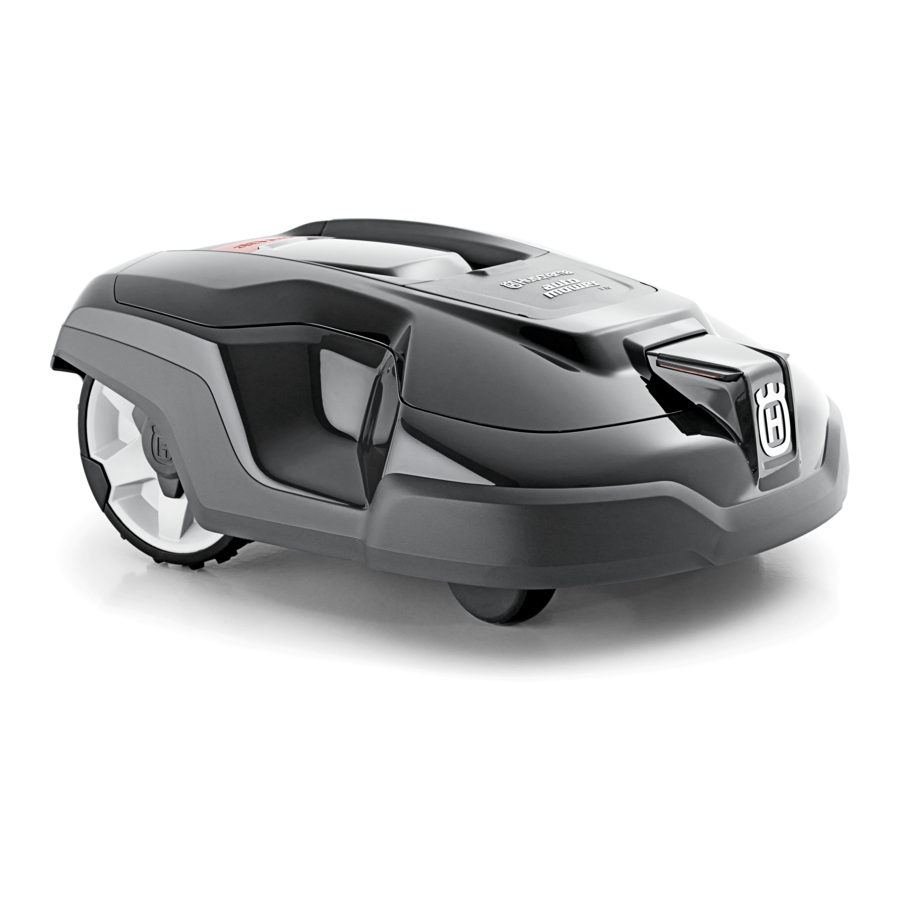
Page 4: Product Overview Automower ® 310/315/315X
® 1.2 Product overview Automower 310/315/315X Automower® 310/315 Automower® 315X The numbers in the figure represent: 13. Rating plate (incl. product identification code) Body 14. Display Hatch to cutting height adjustment 15. Keypad Hatch to display and keypad 16. Cutting system Stop button 17. -
Page 5: Symbols On The Product
23. Loop wire for boundary loop and guide wire This product conforms to the applicable EC Directives. 24. Couplers for loop wire 25. Stakes Noise emission to surroundings. The 26. Connector for the loop wire product’s emissions are set out in 27. -
Page 6: Symbols On The Battery
® The messages function shows error For Automower Connect and ® messages and possible cause for the Connect@Home. Bluetooth wireless problems. communication with your mobile device. The weather timer function automatically adapts the cutting The GPS-supported navigation is intervals to the grass growth. active. -
Page 7: Menu Structure Overview - 1
1.7 Menu structure overview - 1 Schedule Overview/Monday Period 1 Period 2 Copy Reset Current All week days Security Advanced Security level New loop Change Duration Medium High signal PIN code Duration Duration of alarm of time lock Messages Fault Info messages messages... -
Page 8: Menu Structure Overview - 2
1.8 Menu structure overview - 2 Installation Lawn Find charging station Advanced coverage Guide Boundary Charger GPS Auto*** Charging Area 1-3 station range Delay Delay Disable More Disable More time time Test Reset Test Test Reset guide right left How? Disable More Corridor... -
Page 9: Display
1.9 Display The display on the product shows information and settings of the product. To access the display, push the STOP button. 1.10 Keypad Use the keypad on the product to navigate in the menu. To access the keypad, push the STOP button. -
Page 10: Safety
2 Safety 2.1 Safety information 2.1.1 IMPORTANT. READ CAREFULLY BEFORE USE. KEEP FOR FUTURE REFERENCE The operator is responsible for accidents or hazards occurring to other people or property. This appliance is not intended for use by persons (including children) with reduced physical, sensory or mental capabilities (that could affect a safe handling of the product), or lack of experience and knowledge, unless they have been given supervision or instruction concerning use of the appliance by a person... -
Page 11: Safety Definitions
The appliance must be disconnected from the supply mains when removing the battery. WARNING: The product CAUTION: Used if there is a risk of damage to the product, other materials can be dangerous if used or the adjacent area if the instructions incorrectly. - Page 12 If the blades hit foreign objects the code has been entered. blades can be damaged. Always switch off ® • Husqvarna does not guarantee full the product with the main switch before compatibility between the product and other clearing a blockage. Inspect the product for types of wireless systems such as remote damage before staring the product again.
- Page 13 CAUTION: Do not lift the product when it is parked in the charging station. It can damage the charging station and/or the product. Push STOP and pull the product out of the charging station before lifting it. To safely move from or within the work area: WARNING: Use the plug to disconnect the charging station before any Push the STOP button to stop the product.
- Page 14 important that each wire is connected to the right place. 14 - Safety 1440 - 003 - 09.03.2020...
-
Page 15: Installation
• Make a mark on the blueprint where to put the charging station, the boundary wire and the guide wire. Note: Refer to www.husqvarna.com for more • Make a mark on the blueprint where the information about installation. guide wire connects to the boundary wire. - Page 16 CAUTION: Do not put the low-voltage cable in a coil or below the charging station plate. The coil causes max. 5 cm / 2" interference with the signal from the charging station. max. 5 cm / 2" • Put the power supply in an area with a roof and protection from the sun and rain.
- Page 17 recommended to make an eyelet where the guide wire will be connected. Make the eyelet with approximately 20 cm / 8 in. of the boundary wire. " > 5 cm / 2 " 35 cm /14 • Put the boundary wire 30 cm / 12 in. (C) from an obstacle that is 1-5 cm / 0.4-2 in.
- Page 18 • Make an eyelet (F) where the guide wire is sure that the guide wire has as much free area as to be connected to the boundary wire. possible to the left of the guide wire. 3.4.3.1 To put the boundary wire in a slope The product can operate in 35% slopes.
- Page 19 with raised roots, must be isolated or removed. The product can run onto this kind of obstacle causing the blades to be damaged. Use the boundary wire to isolate areas inside the work area by creating islands. When the boundary wires to and from the island are put close together, the product can run over the wire.
-
Page 20: Installation Of The Product
3.5.2 To install the charging station WARNING: Obey national regulations about electrical safety. WARNING: The product is only to be used with the power supply unit supplied by Husqvarna. 20 - Installation 1440 - 003 - 09.03.2020... - Page 21 To install the guide wire is installed. Refer to WARNING: Do not put the power wire on page 22 . supply at a height where there is a risk it can be put in water. Do not put the Connect the low-voltage cable to the power supply on the ground.
-
Page 22: To Put The Wire Into Position With Stakes
Open the connector and put the boundary Connect the guide wire to the boundary wire wire in the connector. with a coupler. Close the connector with a pair of pliers. Put the 2 ends of the boundary wire and the end of the guide wire into the coupler. -
Page 23: To Bury The Boundary Wire Or The Guide Wire
CAUTION: Cutting the grass too low right after installation can damage the wire insulation. Damage to the insulation may not cause disruptions until several weeks or months later. Put the boundary wire and the guide wire on the ground. Put the stakes at a maximum of 75 cm / 30 in. -
Page 24: To Do The Product Settings
flattened. The product is also subjected to Note: If the battery is too low, the product unnecessary wear. needs to charge the batteries fully before the Calibration on calibration starts. Refer to page 24 . 3.10.3.1 To set the schedule To get access to the menu Do steps 1–3 in 3.9.3 Calibration... - Page 25 Push the arrow buttons to select Product work ca- Approximate daily opera- week to reset all schedule settings to pacity tion capacity, m /h, ft factory settings. ® Automower 56 / 603 Push the OK button. ® Automower 68 / 732 3.10.3.5 Security level ®...
- Page 26 To get access to the menu Troubleshooting on page Do steps 1–3 in rectify the fault. Refer to on page 24 . 43 . Use the arrow buttons and the OK button to If the product is disrupted in any way, for Security >...
- Page 27 Use the arrow buttons and the OK button to move through the menu structure Weather timer > Use Weather timer . Weather Push the OK button to select the timer . Push the BACK button. 3.10.4.2 To set the Weather timer frequency Set how frequently the product cuts the grass when the Weather timer is in use.
- Page 28 the distance from the charging station on Use the arrow buttons and the OK button to page 28 . move through the menu structure Settings > Lawn Coverage > Area 1-3 > More > Test . Push the number buttons to select the distance.
- Page 29 irregular method for 3 min. After 3 min the If the product does not dock with the product changes search method to the guide wire charging station, change the position of the method. The product tries to find the guide wire charging station or the guide wire.
- Page 30 station, it always moves to the left of the guide Push the down arrow button. wire. Use the number buttons to select how frequently the product must use each sector. Set in percentage. Push the BACK button. 3.10.9 Reversing distance The reversing distance makes the product move in reverse for a set distance, before the product starts to cut the lawn.
- Page 31 3.10.11.1 Profiles Save a profile for the new charging station, or select a profile in the list. Do steps 1–4 in With the function Profiles, different sets of To save settings to a profile on page 31 , or product settings can be saved. This can be used To use a profile on page 31 .
- Page 32 To get access to the menu Do steps 1–3 in Use the arrow buttons to set the date format on page 24 . and then push the BACK button. Use the arrow buttons and the OK button to 3.10.13.2 To set the language Settings >...
- Page 33 Connect app on To get access to the menu Do steps 1–3 in your mobile device. on page 24 . Sign up for a Husqvarna account in the Use the arrow buttons and the OK button to ® Automower Connect app.
- Page 34 The product must specify APN settings to be able to use and send data via the mobile net. Settings Put the product in the center of the work for Husqvarna SIM is default. area. To get access to the menu ®...
- Page 35 Use the OK button to enable or disable the Flashes when fault function. 3.10.14.6 To avoid collisions with the mower house The wear on the product and the mower house Avoid collisions with decreases when you select mower . To get access to the menu Do steps 1–3 in on page 24 .
-
Page 36: Operation
4 Operation 4.1 Main switch WARNING: Read the safety instructions carefully before you start the product. WARNING: Keep your hands and feet away from the rotating blades. Never put your hands or feet close to or under the product when the motor is running. -
Page 37: Operating Mode Park
4.5 To stop the product the product moves out of the charging station and stops. The product is now prepared to start Push the STOP button on top of the product. operation, but needs confirmation from the Secondary area mode, the operator first. -
Page 38: To Charge The Battery
period must in total be according to the Standby Product work capacity Standby time, mini- time table. Refer to Schedule and Standby on mum hours per day page 37 . ® Automower Timer setting Period 1 (A): 00:00-12:00 ® Automower Timer setting Period 2 (C): 18:00-24:00 ®... -
Page 39: Adjust The Cutting Height
Set the Main switch to position Place the product in the charging station. Slide the product in as far as possible to ensure proper contact between the product and the charging station. Refer to contact Product overview and charging plates in ®... -
Page 40: Maintenance
5 Maintenance 5.1 Introduction - maintenance Husqvarna recommends to use a special cleaning and maintenance kit, available as WARNING: The product must be accessory. Speak to your Husqvarna switched off before any maintenance is representative for more information. done. 5.2.1 Chassis and blade disc Inspect the blade disc and blades once a week. -
Page 41: Replace The Blades
5.3 Replace the blades WARNING: Use blades and screws of the right type. Husqvarna can only guarantee safety when using original blades. Only replacing the blades and reusing the screw can result in a screw wearing during mowing. The blades can then be propelled from under the body and cause serious injury. -
Page 42: Winter Service
5.5 Winter service Take your product to your Husqvarna central service for service prior to winter storage. Regular winter service will maintain the product in good condition and create the best conditions for a new season without any disruptions. Service usually includes the following: •... -
Page 43: Troubleshooting
More suggestions for steps to take in the event of malfunction or symptoms can be found on www.husqvarna.com. 6.2 Fault messages The fault messages in the table below are shown in the display of the product. Speak to your Husqvarna representative if the same message shows frequently. Message Cause Action... - Page 44 Wrong PIN code Wrong PIN code has been entered. Enter the correct PIN code. Contact Five attempts are permitted, and the Husqvarna customer service if you for- keypad is then blocked for a period of get the PIN code. time.
- Page 45 Message Cause Action Charging station The contact between the charging Put the product in the charging station blocked plates on the product on the and con- and check that the charging plates and tact plates on the charging station may contact plates make good contact.
- Page 46 Message Cause Action Electronic problem Temporary electronic or firmware rela- Restart the product. If the problem ted issue in the product. stays speak to your authorized service Loop sensor prob- technician. lem, front/rear Tilt sensor prob- Temporary prob- Invalid sub-device combination Temporary battery problem...
- Page 47 Message Cause Action No loop signal The power supply or low-voltage cable If the LED status indicator on the is not connected. charging station is not lit, it shows that there is no power. Examine the wall socket connection and the residual-cur- rent device.
-
Page 48: Information Messages
6.3 Information messages The information messages in the table below are shown in the display of the product. Speak to your Husqvarna representative if the same message shows frequently. Message Cause Action Low battery The product cannot find the charging Change the position of the guide wire. -
Page 49: Indicator Lamp In The Charging Station
The indicator lamp in the charging station must show a solid or flashing green light for a correct installation. If not, follow the instructions in the troubleshooting guide below. You can also find information on www.husqvarna.com. Speak to your Husqvarna customer service for more information. -
Page 50: Symptoms
If your product does not work as expected, follow the symptoms guide below. There is a FAQ (Frequently Asked Questions) on www.husqvarna.com which provides more detailed answers to a number of standard questions. Contact Husqvarna customer service if you still cannot find the reason for the fault. -
Page 51: Find Breaks In The Loop Wire
Symptoms Cause Action Battery Both the mowing The battery is spent. Replace the battery. Refer to on page 41 . and charging times are shorter than usual. The product is The product has an inbuilt standby peri- No action. parked for hours in od according to the Standby time table. - Page 52 always select the maximum cutting height the Switch the connections between the guide first weeks after installation and then lower the wire and the boundary wire in the charging height one step at a time every second week until station. the desired cutting height has been reached.
- Page 53 Continue until only a very short section of the wire remains which is the difference between a solid green light and a flashing blue light. Then follow instruction in step 5 below. If indicator lamp still flashes blue in step 3 above: Put and back in their original positions.
-
Page 54: Transportation, Storage And Disposal
CAUTION: Only remove the battery Disconnect the battery cable from the main when you dispose the product. When circuit board. you remove the warranty seal, the Husqvarna warranty is no longer applicable. 54 - Transportation, storage and 1440 - 003 - 09.03.2020 disposal... -
Page 55: Technical Data
8 Technical data 8.1 Technical data ® ® ® Dimensions Automower Automower Automower 315X Length, cm / in. 63 / 24.8 63 / 24.8 63 / 24.8 Width, cm / in. 51 / 20.1 51 / 20.1 51 / 20.1 Height, cm / in. - Page 56 ® ® ® Noise emissions measured in Automower Automower Automower 315X the environment as sound pow- Measured sound power noise level, dB (A) Guaranteed sound power noise level, dB (A) Sound pressure noise level at the operator’s ear, dB (A) The noise emission declarations conforms to EN 50636-2-107:2015 ®...
-
Page 57: Registered Trademarks
Connect 4G Power Class 3 23 dBm Husqvarna AB does not guarantee full compatibility between the product and other types of wireless systems such as remote controls, radio transmitters, hearing loops, underground electric animal fencing or similar. The products are made in England or the Czech Republic. See information on the rating plate. Refer to Product overview Automower ®... -
Page 58: Warranty
The blades and wheels are seen as disposable and are not covered by the warranty. If an error occurs with your Husqvarna product, please contact Husqvarna customer service for further instructions. Please have the receipt and the product’s serial number at hand when contacting Husqvarna customer service. -
Page 59: Applicable To Us/Ca Market
Connect Conformity ® This device contains the module FCC ID: XPY1CGM5NNN Issuer: Husqvarna AB, Drottninggatan 2, S-561 82 Huskvarna, Sweden . www.husqvarnagroup.com. Responsible party: Husqvarna Professional Products, Inc. 9335 Harris Corners Parkway Suite 500 Charlotte, NC 28269 United states U.S. - Page 60 Note: This equipment has been tested and found to comply with the limits for a Class B digital device, pursuant to part 15 of the FCC Rules. These limits are designed to provide reasonable protection against harmful interference in a residential installation.
- Page 61 1440 - 003 - 09.03.2020 Applicable to US/CA market -...
- Page 62 62 - Applicable to US/CA market 1440 - 003 - 09.03.2020...
- Page 63 1440 - 003 - 09.03.2020 Applicable to US/CA market -...
- Page 64 ® AUTOMOWER is a trademark owned by Husqvarna AB. © Copyright 2020 HUSQVARNA. All rights reserved. www.husqvarna.com Original instructions 1142215-95 2020-03-09...