Siemens SINUMERIK 840D sl Manual
Operator panel front
Hide thumbs
Also See for SINUMERIK 840D sl:
- Function manual (2184 pages) ,
- Programming manual (1334 pages) ,
- Commissioning manual (1102 pages)
Table of Contents
Quick Links
Table of Contents

Related Manuals for Siemens SINUMERIK 840D sl


Summary of Contents for Siemens SINUMERIK 840D sl
- Page 1 Fundamental safety instructions Description Installation SINUMERIK Connecting SINUMERIK 840D sl Operator panel front: OP 012 Networking Service and maintenance Manual Technical specifications Spare parts Valid for: Control system SINUMERIK 840D sl/840DE sl 05/2019 A5E36371591B AB...
- Page 2 Note the following: WARNING Siemens products may only be used for the applications described in the catalog and in the relevant technical documentation. If products and components from other manufacturers are used, these must be recommended or approved by Siemens. Proper transport, storage, installation, assembly, commissioning, operation and maintenance are required to ensure that the products operate safely and without any problems.
-
Page 3: Table Of Contents
Table of contents Fundamental safety instructions........................5 General safety instructions.......................5 Equipment damage due to electric fields or electrostatic discharge ........8 Warranty and liability for application examples ................8 Industrial security ........................9 Residual risks of power drive systems ...................11 Description..............................13 Overview ..........................13 Operator control and display elements ..................14 2.2.1 View ............................14 2.2.2... - Page 4 Table of contents 5.3.2 Networks without connection to the company network ............49 5.3.2.1 Configuration 1: NCU and TCU....................49 5.3.3 Networks with NCU connection to the company network ............50 5.3.3.1 Configuration 2: NCU and TCU....................50 5.3.3.2 Configuration 3: PCU/IPC with TCU on NCU.................51 5.3.3.3 Connecting the programming device (PG) to the NCU ............52 5.3.4...
-
Page 5: Fundamental Safety Instructions
Fundamental safety instructions General safety instructions WARNING Electric shock and danger to life due to other energy sources Touching live components can result in death or severe injury. ● Only work on electrical devices when you are qualified for this job. ●... - Page 6 Fundamental safety instructions 1.1 General safety instructions WARNING Electric shock due to equipment damage Improper handling may cause damage to equipment. For damaged devices, hazardous voltages can be present at the enclosure or at exposed components; if touched, this can result in death or severe injury.
- Page 7 ● If you come closer than around 2 m to such components, switch off any radios or mobile phones. ● Use the "SIEMENS Industry Online Support app" only on equipment that has already been switched off. WARNING...
-
Page 8: Equipment Damage Due To Electric Fields Or Electrostatic Discharge
Fundamental safety instructions 1.3 Warranty and liability for application examples Note Important safety notices for Safety Integrated functions If you want to use Safety Integrated functions, you must observe the safety notices in the Safety Integrated manuals. Equipment damage due to electric fields or electrostatic discharge Electrostatic sensitive devices (ESD) are individual components, integrated circuits, modules or devices that may be damaged by either electric fields or electrostatic discharge. -
Page 9: Industrial Security
In order to protect plants, systems, machines and networks against cyber threats, it is necessary to implement – and continuously maintain – a holistic, state-of-the-art industrial security concept. Products and solutions from Siemens constitute one element of such a concept. - Page 10 Fundamental safety instructions 1.4 Industrial security WARNING Unsafe operating states resulting from software manipulation Software manipulations, e.g. viruses, Trojans, or worms, can cause unsafe operating states in your system that may lead to death, serious injury, and property damage. ● Keep the software up to date. ●...
-
Page 11: Residual Risks Of Power Drive Systems
Fundamental safety instructions 1.5 Residual risks of power drive systems Residual risks of power drive systems When assessing the machine- or system-related risk in accordance with the respective local regulations (e.g., EC Machinery Directive), the machine manufacturer or system installer must take into account the following residual risks emanating from the control and drive components of a drive system: 1. - Page 12 Fundamental safety instructions 1.5 Residual risks of power drive systems Operator panel front: OP 012 Manual, 05/2019, A5E36371591B AB...
-
Page 13: Description
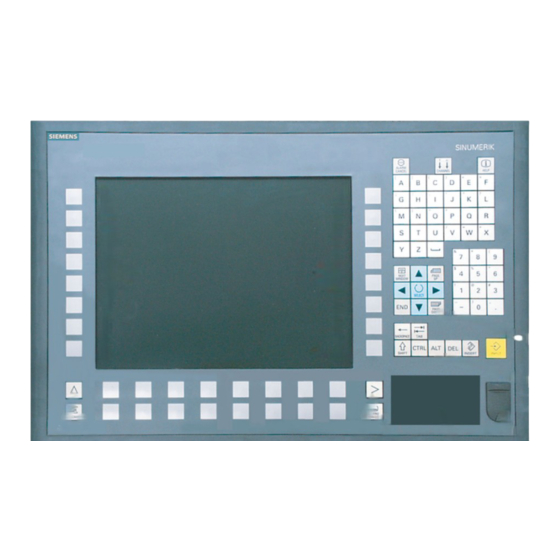
Description Overview The SINUMERIK OP 012 operator panel front and 12.1" TFT color display with a resolution of 800 x 600 pixels (SVGA) features a 59-key membrane keyboard as well as 2 x (8 + 2) horizontal and 2 x 8 vertical softkeys. The 2 x 8 vertical softkeys can be used as direct keys. It is fixed from the rear using special clamps that are included in the delivery scope. -
Page 14: Operator Control And Display Elements
Description 2.2 Operator control and display elements Operator control and display elements 2.2.1 View ① Alphabetic key group ② Numeric key group ③ Cursor key group ④ Control key group ⑤ Front USB interface ⑥ Touchpad mouse ⑦ Menu select key ⑧... -
Page 15: Keyboard
Description 2.2 Operator control and display elements 2.2.2 Keyboard Keyboard Several keys and keypads are installed on the operator panel front: ● The alphabetic block contains the letters A - Z and the space character. ● The numeric block contains the digits 0 - 9, and the characters "-", "/", "=", "+" and ".". ●... -
Page 16: Screen Saver
Description 2.2 Operator control and display elements Function corresponds to the Function corresponds to the PC key function PC key function Page down Delete Cursor up Insert Cursor left Enter Cursor right Cursor down 5 (in numeric key group) A, ..., Z... -
Page 17: Touchpad Mouse
Description 2.2 Operator control and display elements 2.2.4 Touchpad mouse Operation All of the mouse functions are based on 2-finger operation. The principle of operation of the OP 012 touchpad mouse is explained in the following table with reference to a classic 2-key mouse. Action Touch event Corresponds to... -
Page 18: Interfaces
Description 2.3 Interfaces Interfaces Front USB 1.1 Full Speed (12 Mbps), high power (500 mA), Type A connector for connecting an external keyboard, mouse and USB flash drive (see View (Page 14)). Note Note that the electromagnetic compatibility of commercially available peripheral devices operated via the USB interface is usually rated for office use only. -
Page 19: Installation
Installation Preparation for mounting WARNING Electric shock in the event of an individual error when grounding is insufficient If the panel is installed with inadequate grounding in an environment with hazardous voltages, this may cause an electric shock in the event of an individual error. This can result in death, serious injury and material damage. - Page 20 Installation 3.1 Preparation for mounting This retaining method also enables the IP65 degree of protection (but only in conjunction with a circumferential seal and when the protective USB cap is fitted). Note The OP 012 is supplied with 12 "small" tension jacks. If you have the "large" tension jacks (6FC5248-0AF06-0AA0) in stock, then you can also use these.
-
Page 21: Assembling An Op 012 And A Pcu
Installation 3.2 Assembling an OP 012 and a PCU Figure 3-2 Dimension sheet for attaching the PCU to the OP 012 operator panel front Assembling an OP 012 and a PCU When combining an OP 012 and PCU and possibly a direct key module, it is advisable to assemble them prior to installation in an assembly panel. - Page 22 Installation 3.2 Assembling an OP 012 and a PCU Requirement The PCU must now be bolted to the mounting brackets prior to assembly (if this has not already been done). See Section in the “PCU 50.5” manual under “Assembly" → "Assembly of PCU and operator panel front (standard mounting)"...
- Page 23 Installation 3.2 Assembling an OP 012 and a PCU ① I/O USB cable K1 ② Display cable K2 Figure 3-4 (A) Assembling PCU and OP 012 ① I/O / USB cable K1 ② Display cable K2 Figure 3-5 (B) Correct connection of I/O-USB and display cables to the PCU Operator panel front: OP 012 Manual, 05/2019, A5E36371591B AB...
-
Page 24: Mounting On The Mounting Wall
Installation 3.3 Mounting on the mounting wall ① Knurled screw Figure 3-6 (C) OP 012 and PCU after assembly Note The OP 012 and TCU assembly is similar to that for a PCU. Mounting on the mounting wall The clearance at the rear of the PCU/TCU must be at least 10 mm to ensure sufficient ventilation (see Figure 3-2 Dimension sheet for attaching the PCU to the OP 012 operator panel front (Page 21)). -
Page 25: Softkey Labeling
(Page 89)). Note Use the "Arial" font to format text. This font is comparable to the "Univers S57" font, used by Siemens for the key labeling. Procedure 1. Letter the mat side of the film using a laser printer. 2. Cut the printed labels along the preprinted lines. - Page 26 Installation 3.4 Softkey labeling Operator panel front: OP 012 Manual, 05/2019, A5E36371591B AB...
-
Page 27: Connecting
Connecting Pin assignment of the interfaces The pins of the component interfaces are assigned as specified in the tables below. Any deviations are indicated at the relevant point. Signal type: Input Output Bidirectional (inputs/outputs) Power supply Ground (reference potential) or N.C. (not connected) Power supply X206 Connector designation: X206... - Page 28 Connecting 4.1 Pin assignment of the interfaces In principle, USB interfaces have the following characteristics: ● Integrated power supply up to 500 mA for each socket. ● Maximum cable length 3 m (Length including the supply cable to the hub and the connected terminal device;...
- Page 29 Connecting 4.1 Pin assignment of the interfaces Ethernet RJ45 interface X202 Connector type: Standard RJ45 socket Max. data transmission rate: 10/100/1000 Mbit/s Max. cable length: 100 m Table 4-2 Assignment of the Ethernet RJ45 interface 1000 Mbit/s Connector Name Type Remark Bidirectional pair A+ Bidirectional pair A-...
- Page 30 Connecting 4.1 Pin assignment of the interfaces Table 4-3 Allocation of the I/O USB interface Connector Name Type Meaning Ground P12C +power supply for backlight inverter BL_ON Backlight On P5V_fused +5 V VCC (fused in PCU/TCU) Ground P3V3_fused +3.3 V VCC (fused in PCU/TCU) 7 - 10 N.C.
- Page 31 Connecting 4.1 Pin assignment of the interfaces Table 4-4 Allocation of the LVDS display interface Connector Name Type Meaning P5V_D_fused +5 V display supply voltage (fused in PCU/ TCU) RXIN0- Bit 0 (-) LVDS input signal RXIN0+ Bit 0 (+) P3V3_D_fused +3.3 V display supply voltage (fused in PCU/ TCU)
- Page 32 Connecting 4.1 Pin assignment of the interfaces Figure 4-1 Assignment of the direct keys to the vertical softkeys of an operator panel front 16 digital inputs (5 V) can be fetched via the X11 connector. Connector designation: Connector type: 20-pin plug connector Max.
-
Page 33: Handling Membrane Connectors
Connecting 4.2 Handling membrane connectors Name Type Meaning P5V / CON1 + 5 V input voltage P5V / CON2 + 5 V input voltage Ground Ground The inputs are electrically isolated for MCP / MPP / HAM and DTM. For the TCU, it is evaluated whether the direct keys have been connected. Power consumption: 100 mA for MCP / MPP / HAM;... - Page 34 Connecting 4.2 Handling membrane connectors Operator panel front: OP 012 Manual, 05/2019, A5E36371591B AB...
-
Page 35: Networking
Networking System settings 5.1.1 Thin Client Unit (TCU) TCU overview The Thin Client Unit (TCU) for the distributed configuration permits spatial separation of the SINUMERIK operator panel front (OP/TP) and the SINUMERIK PCU/SIMATIC IPC or NCU. With SINUMERIK solution line, the TCU is used to visualize the user interface of the PCU 50, SIMATIC IPC for SINUMERIK with PCU basic software or NCU. -
Page 36: Settings For Sinumerik Solution Line
Networking 5.1 System settings Supplementary conditions The following supplementary conditions apply for the operation of a TCU: ● In the system network, the number of active thin clients is limited: – A maximum of 2 TCUs: NCU 710.3 PN – A maximum of 4 TCUs: NCU 720.3 PN or NCU 730.3 PN –... - Page 37 Networking 5.1 System settings The following rules apply for assignment of IP addresses in the system network: ● For all NCUs and/or PCUs/IPCs, the commissioning engineer assigns fixed IP addresses in the associated address bands, as well as appropriate computer names (host names). All other operator components are automatically assigned an IP address by the DHCP server.
-
Page 38: System Boot With System Network
Networking 5.1 System settings 5.1.3 System boot with system network System behavior at boot The system boot behavior is based on the following principle: ● For the configuration of an NCU 7x0 with a PCU/IPC, the default for a network configuration is as follows: The NCU keeps the default IP address 192.168.214.1 on X120, the PCU/IPC keeps the default IP address 192.168.214.241 on Eth2. -
Page 39: Factory Default Settings
Networking 5.1 System settings 5.1.4 Factory default settings Meaning of the symbols: ○ Eth 1 as a DHCP client ● Eth 2 as a DHCP server ■ Eth 2 with a fixed IP address Preconfiguration of the TCU The TCU is configured as a DHCP client and primarily accepts IP addresses from SINUMERIK components, from the DHCP server of such components that are inherent to SINUMERIK, for example, an NCU at X120 or a PCU/IPC on the system network or from a standard DHCP server. - Page 40 Networking 5.1 System settings Preconfiguration of the NCU On the X120, the NCU is preconfigured for the SINUMERIK DHCP protocol. The NCU is pre- selected here as a SINUMERIK DHCP server. On X120, the NCU occupies the fixed IP address 192.168.214.1 with the subnet mask 255.255.255.0 in its capacity as a DHCP server.
-
Page 41: Commissioning Tcu
Networking 5.2 Commissioning TCU IP address ranges reserved for NCU and PCU/IPC The following defaults apply on delivery: ● Connection to the system network with subnet mask 255.255.255.0: IP address Network station Remark 192.168.214.1 NCU on X120 Default 192.168.214.2 – 9 For additional NCUs with a fixed IP address on Not assigned the system network... -
Page 42: Settings In The "Tcu.ini" File
For operator panel fronts without keys, a virtual keyboard automatically appears. 5.2.2 Settings in the "TCU.ini" file Directories The tcu.ini file is created in the following directories: NCU: ../siemens/system/etc/tcu.ini ../user/system/etc/tcu.ini ../oem/system/etc/tcu.ini PCU/IPC (Windows 7 and Windows 10): C:\ProgramData\Siemens\MotionControl\siemens\System\etc\tcu.ini C:\ProgramData\Siemens\MotionControl\user\System\etc\tcu.ini Operator panel front: OP 012... -
Page 43: Displacement Mechanism For Tcus
Networking 5.2 Commissioning TCU C:\ProgramData\Siemens\MotionControl\oem\System\etc\tcu.ini Note The following entries are evaluated by SINUMERIK Operate: ● VNCServer/VetoMode ● VNCServer/AlarmBoxTimeOut ● VNCServer/FocusTimeout ● VNCServer/AdaptResolution ● VNCServer/MaxActiveTCUs ● VNCViewer/ExternalViewerSecurityPolicy Restrictions Restrictions for such external operator control units are: ● Neither MCP and direct keys nor an EKS system can be assigned. This also means that these devices cannot be activated to be an operator control unit in the system. -
Page 44: Disable Switchover Between Tcu Via Plc
Networking 5.2 Commissioning TCU Supplementary conditions The following supplementary conditions apply when operating the TCU: 2 active TCU connected in parallel to NCU 710.3 PN 4 active TCU connected in parallel to NCU 720.3 PN, NCU 730.3 PN 4 active TCUs connected in parallel to PCU/IPC Displacement rules You configure the displacement mechanism in SINUMERIK Operate in the "Setup"... - Page 45 Networking 5.2 Commissioning TCU HMI ↔ PLC data interface The "switchover disable" function is always active and does not have to be switched on explicitly. The function is controlled by a data bit in the PLC. The HMI transfers the active OP to the PLC, thus forming the basis of the control function in the PLC.
- Page 46 Networking 5.2 Commissioning TCU While this message is displayed, operations on the OP with the user authorization can still be carried out unaffected. Note Active switching of an OP to another PCU/IPC is possible The switchover disable only relates to changing the user authorization on the OPs in a shadowing group on a PCU/IPC.
-
Page 47: Example: How To Select The Behavior Of The Tcus During Boot Up
Networking 5.2 Commissioning TCU The settings for the right to veto are stored in file tcu.ini and are only effective if the operating software is installed on the PCU/IPC. You can use the operating software on the OP or TCU in the same way as on an OP connected directly to the PCU/IPC. -
Page 48: Network Configuration
Networking 5.3 Network configuration Network configuration 5.3.1 Permissible network topologies Ethernet connection A SINUMERIK 840 D sl can only be operated as a network within which the individual components communicate with one another via Ethernet connections. This network must be set up. -
Page 49: Networks Without Connection To The Company Network
Networking 5.3 Network configuration 5.3.2 Networks without connection to the company network 5.3.2.1 Configuration 1: NCU and TCU A direct Ethernet connection is used to connect a TCU to X120 of the NCU. NCU and TCU are suitably preconfigured with IP addresses. The IP addresses are not significant for further operation. -
Page 50: Networks With Ncu Connection To The Company Network
Networking 5.3 Network configuration 5.3.3 Networks with NCU connection to the company network 5.3.3.1 Configuration 2: NCU and TCU The TCU is directly connected to the NCU via a crossed Ethernet cable. On X130, the NCU is connected to a switch to the company network with a straight cable. As in configuration 1, there is a direct Ethernet connection between a TCU and X120 of the NCU. -
Page 51: Configuration 3: Pcu/Ipc With Tcu On Ncu
Networking 5.3 Network configuration 5.3.3.2 Configuration 3: PCU/IPC with TCU on NCU In this configuration, a switch is also required for the system network. All components are connected using straight Ethernet cables. On X120, the NCU occupies the fixed IP address 192.168.214.1 in its capacity as a DHCP server (not used in this configuration). -
Page 52: Connecting The Programming Device (Pg) To The Ncu
Networking 5.3 Network configuration 5.3.3.3 Connecting the programming device (PG) to the NCU Description For service purposes a programming device is connected to the NCU at X127 as a standard DHCP client (automatically obtain an IP address). An NCU is a standard DHCP server on X127. On X127, the NCU occupies the fixed IP address 192.168.215.1 with the subnet mask 255.255.255.224. -
Page 53
The config.ini file is located in the following directory: NCU: /user/common/tcu/
/common/tcu PCU/IPC (Windows 7 and Windows 10): C:\ProgramData\Siemens\MotionControl\user\common\tcu\ \common\tcu The config.ini file must be stored on the boot server (active DHCP). Operator panel front: OP 012 Manual, 05/2019, A5E36371591B AB... -
Page 54: Service And Diagnostics
Networking 5.4 Service and diagnostics Example: [Station] maxhostindex=2 /* Number of nodes that are defined under [host_1] and [host_2]. mcpIndex=192 tcuIndex=1 eksIndex=0 [host_1] Address=192.168.214.1 /* Address of the NCU to which the connection is established during booting. [host_2] Address=157.163.230.202 /* Address of the PC password=123456 /* Password of the VNC server on the PC Switching over between the nodes... - Page 55 Networking 5.4 Service and diagnostics ① "Main menu" title followed by the TCU name in brackets ② Central area with the list of servers and two further permanent items, "Select service session" and "Service this panel": ● "Select service session" triggers a server scan which detects all the VNC servers in the local system network.
- Page 56 Networking 5.4 Service and diagnostics "Details" softkey The following connection data for the selected device appears when the "Details" softkey is pressed: Figure 5-3 TCU menu: Connection data Operator panel front: OP 012 Manual, 05/2019, A5E36371591B AB...
-
Page 57: Operating The Tcu Menu "Service Sessions
Networking 5.4 Service and diagnostics 5.4.2 Operating the TCU menu "Service sessions" "Service sessions" dialog When "Select service session" is selected from the main menu, the resulting process begins by triggering a server scan: Figure 5-4 TCU menu: Scanning After this, the following dialog appears: Operator panel front: OP 012 Manual, 05/2019, A5E36371591B AB... - Page 58 Networking 5.4 Service and diagnostics Figure 5-5 TCU menu: Active sessions Central area with the server list: The individual server lines contain either "Show WHAT on NAME (IP)" or the IP address only where the name is unknown. Session number VNC server Session 0 Session 4...
-
Page 59: Operating The Tcu Menu "Service Menu
Networking 5.4 Service and diagnostics precise details on the reason for the loss of function. With more favorable scenarios, the session name for the VNC server will also be specified along with its resolution. The connection and HMI status are monitored on a regular basis in the background. This may mean that these specifications change spontaneously if a change is made on the relevant server, e.g. - Page 60 Networking 5.4 Service and diagnostics The following menu items are available here: ● "Show status" shows status information, for example: Software version, hardware information, TCU network data, and their configuration: Figure 5-7 TCU menu: OP status ● "Show local logfile" shows a filtered version of the system log file in the /var/log/ messages directory, which contains only the messages of the local TCUs.
- Page 61 Networking 5.4 Service and diagnostics Figure 5-8 TCU menu: Local log file ● "Show logfile of remote devices" shows the log file of the other devices in the network: The syslog messages of devices in the system network which send syslog messages by broadcast, such as NCU 7x0, ...
-
Page 62: Operating The Tcu Menu "Modify Settings
Networking 5.4 Service and diagnostics 5.4.4 Operating the TCU menu "Modify settings" "Modify settings for operator panel (TCU)" dialog The following dialog appears when "Modify settings" is selected from the main menu: Figure 5-9 TCU menu: Settings The following TCU parameters are set here during the first commissioning: ●... -
Page 63: Operating The Menu For A New Tcu Or Spare Part Tcu
Networking 5.4 Service and diagnostics ● "Virtual Keyboard" (Auto/On/Off) Specifies whether a virtual keyboard is shown on the screen for touch screens. Depending on the panel features (Auto), the HMI decides whether a touch screen or keyboard is available. This parameter can also be set manually (On/Off). ●... - Page 64 Networking 5.4 Service and diagnostics Figure 5-10 TCU menu: New TCU If all TCUs are active, the new TCU cannot be a spare part. The system will then automatically switch to the name assignment phase after a set period of time has elapsed. Operator panel front: OP 012 Manual, 05/2019, A5E36371591B AB...
- Page 65 Networking 5.4 Service and diagnostics Figure 5-11 TCU menu: Name of TCU If a TCU30.3 is to be operated with a software version < 4.7 SP2, the TCU is operated in compatibility mode. If required, you can view and change the emulation type in the settings. Replacing a device If "Replacement"...
- Page 66 Networking 5.4 Service and diagnostics Figure 5-12 TCU menu: Replacement TCU With the TCU30.3, after selecting the TCU to be replaced, a further dialog to select the emulation type can be displayed in compatibility mode: Operator panel front: OP 012 Manual, 05/2019, A5E36371591B AB...
- Page 67 Networking 5.4 Service and diagnostics If a static.ini of the TCU to be replaced (as of SW4.5) is found on the server, then the type of the old TCU is preselected based on the HW ID found there. If this is not the case, the TCU20.2 type is selected.
-
Page 68: How To Register A Tcu On The System Network
Networking 5.4 Service and diagnostics Assigning a name If, as described above, the system automatically follows the "New" path, an additional message will appear: "This operator panel (TCU) must be new, because there are no inactive panels." This message will not appear if "New" is selected manually. Figure 5-13 TCU menu: Name of TCU An available TCU name is suggested in the input field, although the user is able to change this. - Page 69 Networking 5.4 Service and diagnostics Using the TCU Procedure: 1. Connect the TCU. This opens the "New operator panel (TCU)" dialog. 2. Select "New" to connect a new TCU and "OK" to confirm. 3. In the next dialog, accept the name suggested by the system or enter a name and confirm this with "OK".
- Page 70 Networking 5.4 Service and diagnostics Procedure for the HT 8 1. Connect the HT 8 to a connection module and calibrate the touch screen. Additional softkeys are available for convenient touch panel operation: – "OK" has the same function as the key –...
-
Page 71: This Is How You Register A Spare Part Tcu
Networking 5.4 Service and diagnostics Specifying settings without machine control panel If a PCU, IPC or TCU does not have a machine control panel (MCP), one of the two following options must be set: ● MCP address = 0 or no entry After the change of user authorization, there is no switchover of the machine control panel;... -
Page 72: Booting Of The Tcu
Networking 5.4 Service and diagnostics 5.4.8 Booting of the TCU 5.4.8.1 Messages during booting Messages when booting While the TCU boots, a progress indicator is displayed with messages showing the current status after the BIOS has been loaded and before the operating system is started. While the IP address is being determined via DHCP and the TFTP is being downloaded (boot image), a progress bar indicates that booting of the TCU is not yet complete, or that a fault has occurred. -
Page 73: Diagnostics Options During Booting
Networking 5.4 Service and diagnostics 5.4.8.2 Diagnostics options during booting Diagnostics while booting supplementary conditions In the following supplementary conditions, the diagnostics window is displayed and booting of the TCU is interrupted: ● When the <1 / F1> function is selected during booting ●... -
Page 74
Networking 5.4 Service and diagnostics Press <1 / F1> to continue If you select function
in the diagnostics window, the, detailed diagnostic information is output. Key / text Meaning F1 ... F6 Navigate within the window (alternatively, the relevant keys on the OP can be used). F7 -detail Display less information F8 +detail... -
Page 75: Service And Maintenance
Service and maintenance Cleaning the device The operator panel front is designed for low-maintenance operation. Nevertheless, you must regularly clean the display. Note Switch the device off for cleaning Clean the device only when it is switched off. This way, you ensure that you cannot unintentionally trigger any functions by touching the touch-sensitive glass surface. - Page 76 Service and maintenance Spare parts There are no parts of this device that can be replaced by the user. Suspected malfunction If you suspect a malfunction due to unusual product reactions, isolate the device from power. Immediately inform qualified personnel to check the function and ensure that the product functions correctly.
-
Page 77: Technical Specifications
Technical specifications Technical data Safety Safety class III; PELV according to EN 50178 Degree of protection accord‐ Front side IP65 ing to EN 60529 Rear side IP00 Approvals CE/cULus/EAC/KC/RCM Electrical data Power consumption typically approx. 5 W (without load at USB interface, maximum approx. -
Page 78: Secondary Electrical Conditions
Technical specifications 7.2 Secondary electrical conditions Secondary electrical conditions 7.2.1 Power supply Requirements for DC power supplies WARNING Electric shock due to connection of an unsuitable power supply When equipment is connected to an unsuitable power supply and/or insufficiently grounded or rear cover (Page 19), exposed components may carry a hazardous voltage that might result in serious injury or death. -
Page 79: Grounding Concept
7.2.2 Grounding concept Components The SINUMERIK 840D sl system consists of a number of individual components which have been designed so that the system complies with the appropriate EMC and safety standards. The individual system components are: ● Numerical Control Unit (NCU) ●... -
Page 80: Emc Limit Values In South Korea
● Only use cables approved by SIEMENS for the signal lines from and to the Control Unit. ● Signal cables must not be routed close to strong external magnetic fields (e.g. motors and transformers). -
Page 81: Ambient Climatic And Mechanical Conditions
Ambient climatic and mechanical conditions 7.3.1 Transport and storage conditions The components of the SINUMERIK 840D sl system exceed the requirements according to EN 61800‑2 with regard to shipping and storage conditions. The following data applies under the following conditions: ●... -
Page 82: Operating Conditions
Remove the transport protective foil and packaging material before installing the components. 7.3.2 Operating conditions The components of the SINUMERIK 840D sl system are intended for a weatherproof, fixed location. The documented environmental conditions apply to the climate in the immediate vicinity of the units and to the entry of the cooling air. -
Page 83: Cooling
Technical specifications 7.3 Ambient climatic and mechanical conditions Ambient climatic conditions Relative humidity 5 ... 95% (no condensation) Oil mist, salt mist, ice formation, con‐ Not permitted densation, dripping water, spraying water, splashing water and water jets Biological, chemical, electrical and mechanical influences, pollutants Biological environmental conditions Class 3B1 according to EN 60 721-3-3: Mold, mold growth, slime, rodents, termites and other animal... - Page 84 Technical specifications 7.3 Ambient climatic and mechanical conditions Convection surface area A [m The surface areas of the front and bottom sides are not included in the convection surface area calculation. Note A recommended value for the power loss of the operator control components is contained in the "Technical data"...
- Page 85 Technical specifications 7.3 Ambient climatic and mechanical conditions Figure 7-1 Means of heat dissipation Fan design ● The fan must be positioned to produce an optimum heat dissipation. A clearance of 10 mm must be maintained in front of the fan. ●...
-
Page 86: Standards And Approvals
Technical specifications 7.4 Standards and approvals Guidelines If the convection area A [m ] does not suffice for the "heat dissipation using natural convection", then use: ● "Heat dissipation using natural convection and internal turbulence" for hot spots and heat concentrations in housings subject to space constraints. -
Page 87: Recycling And Disposal
China RoHS The products comply with the China RoHS directive Further information on this can be found on the Internet at the following link: SIOS (https://support.industry.siemens.com/cs/document/ 109738656/china-rohs-manufacturer?dti=0&lc=en-WW) Risk assessment The following standards must be used to perform the risk assessment: ●... - Page 88 Technical specifications 7.5 Recycling and disposal Operator panel front: OP 012 Manual, 05/2019, A5E36371591B AB...
-
Page 89: Spare Parts
Spare parts Overview The diagram shows the OP 012 operator panel front dismantled into its individual parts. Figure 8-1 Individual parts for the OP 012 operator panel front The components listed in the following table with an article number are available as spare parts. ①... -
Page 90: Replacement
Spare parts 8.2 Replacement Figure 8-2 Dimensions for slide-in labels Replacement NOTICE Risk of damage to sensitive components due to static electricity Spare parts must always be replaced by properly trained personnel! USB cap / tension jack The replacement of the USB sealing cap and tension jacks will not be described since it is simple and self-explanatory. - Page 91 Spare parts 8.2 Replacement Operator panel front When replacing the operator panel front, the previous USB interface, display and keyboard controller can continue to be used. They are therefore disassembled and reassembled after the appropriate component has been replaced. Note We recommend reusing the keypad controller to prevent any loss of the control parameters that have been programmed in.
- Page 92 Spare parts 8.2 Replacement ① Touchpad mouse ② Front USB interface ③ Keyboard controller ④ Connection X1 for IO-USB cable K1 ⑤ Direct key connection X11 ⑥ Membrane connectors X7 and X8 for connecting the operator panel front keyboard. ⑦ Connection X12 (reserved) ⑧...
-
Page 93: Index
Index Boot server, 51 Heat dissipation Means of heat dissipation, 84 HT 8 rotary coding switch, 70 Care, 75 Cleaning product, 75 CompactFlash Card, 36 Individual parts Company network, 37 OP 012, 89 Connecting a PG, 52 Connection conditions EMC measures, 78 End user interface, 78 Key symbols Membrane connectors, 33... - Page 94 Index Potential equalization, 79 Protective separation Connection conditions, 78 Scope of maintenance, 75 Signal cables, 79 SINUMERIK DHCP client, 39 SINUMERIK DHCP server, 40 Slide-in labels OP 012, 89 Star structure, 36 Starting up the system, 38 SVGA resolution OP 012, 13 Switchover disable, 44 System network, 36 Configuring, 68...