Bosch APC‑AMC2‑4WCF Installation Manual
Access modular controller 2
Hide thumbs
Also See for APC‑AMC2‑4WCF:
- Installation manual (72 pages) ,
- Installation manual (54 pages) ,
- Installation manual (60 pages)
Table of Contents
Table of Contents

Related Manuals for Bosch APC‑AMC2‑4WCF


Summary of Contents for Bosch APC‑AMC2‑4WCF
- Page 1 Access Modular Controller 2 APC‑AMC2‑4WCF | ADS‑AMC2‑4WCF Installation manual...
-
Page 3: Table Of Contents
Tamper Protection Operating Status Display of the AMC2 Configuring the Ethernet Interface Troubleshooting 5.3.1 Resetting the Software 5.3.2 Resetting the Device to Factory Default Technical Data Appendices Connecting Diagrams Index Bosch Security Systems B.V. Installation manual 2020-01 | V02 |... -
Page 4: Safety Instructions
10. Lightning - For added protection during electrical storms external lightning conductors can be installed. This prevents power surges from damaging the unit. 11. The units should be installed in locations with restricted access. 2020-01 | V02 | Installation manual Bosch Security Systems B.V. -
Page 5: Safety Precautions
0°C to 50°C. Disposal Your Bosch product is designed and manufactured with high-quality materials and components which can be recycled and reused. This symbol means that electrical and electronic equipment, at their end-of-life, should be disposed of separately from your household waste. -
Page 6: Unpacking
Do not attempt to put the unit into operation if components are damaged. If any parts are missing, inform your customer service representative or a Bosch Security Systems salesperson. The shipping carton is the safest transport container for the unit. Store it and the other packaging material for future use. -
Page 7: Important Information
Bosch Security Systems retains all rights not expressly granted. Nothing in this license constitutes a waiver of Bosch’s rights under the U.S. Copyright laws or any other federal or state law. If you have any questions concerning this license, please, write to:... -
Page 8: Introduction
The relay outputs can be used to activate lock mechanisms if access is granted, or activate the burglar alarm system if an intrusion or system alert is detected. If the eight inputs and eight 2020-01 | V02 | Installation manual Bosch Security Systems B.V. -
Page 9: Equipment Configuration
Jumper: Interface selector RS-485 host connection, RS-485 two wire or RS-485 four wire (depends on external wiring) Configurable RS-485 host interface Docking port for compact flash memory Configurable RS-232 host interface (ribbon cable connector) Configurable 10/100 Mbit/s Ethernet host interface Bosch Security Systems B.V. Installation manual 2020-01 | V02 |... -
Page 10: Performance Characteristics
Intelligent access manager for 1 - 8 entrances (for example doors, man traps, barriers) – Host address selectable using DIL sliding switch. – Four possible configurable host interfaces: – Ethernet (= standard) – RS-485 2-wire 2020-01 | V02 | Installation manual Bosch Security Systems B.V. -
Page 11: System Overview
Tamper contact for external covers Notice! If an external power supply is used, this should also guarantee an uninterruptable power supply (UPS). Example: Bosch power supply APS-PSU-60 (F.01U.282.970). System Overview The Access Controller AMC2-4R4 is connected between the management host system and different peripheral devices. - Page 12 The extension interface supports up to three additional I/O boards (AMC2-8IOE, AMC2-16IE, or AMC2-16IOE). All extension boards are controlled by the AMC2 and are freely combinable. 2020-01 | V02 | Installation manual Bosch Security Systems B.V.
-
Page 13: Installing
Attach the AMC2-4W into the upper edge of the mounting rail [1], then push down the device and snap it onto the rail by pushing it towards the back [2]. Figure 4.1: Mounting the AMC2 on a mounting rail Bosch Security Systems B.V. Installation manual 2020-01 | V02 |... -
Page 14: Unmounting
Push down the AMC2-4W until the lower edge snaps out of the mounting rail [1]. Pull the lower end of the AMC2-4W from the mounting rail [2]. Figure 4.2: Unmounting the AMC2 from a mounting rail 2020-01 | V02 | Installation manual Bosch Security Systems B.V. -
Page 15: Opening The Case
The AMC2-4W case consists of a top cover mounted with a two-point snap-in closure on a chassis. To open the case, push down the two snap-ins with a screwdriver, then swing the cover down. Figure 4.3: Opening the AMC2 case Bosch Security Systems B.V. Installation manual 2020-01 | V02 |... -
Page 16: Closing The Case
[1]. Please ensure that the BOSCH logo is not upside-down. The upper edge of the front cover now aligns with the two-point snap-in closures on the upper edge of the back cover [2], and may thus be clicked gently into place. - Page 17 These specifications apply to power supply, readers, relay outputs, and extension interface. Regarding inputs, specific voltage-drop values need to be taken into account. Refer to Connecting Analog Input Devices, page 32. Bosch Security Systems B.V. Installation manual 2020-01 | V02 |...
-
Page 18: Grounding And Shielding
JP1 is set at the first device only (= A2) Settings for jumper JP2: If the ground conductor and the shield on the host are not connected and: 2020-01 | V02 | Installation manual Bosch Security Systems B.V. -
Page 19: Grounding For Extension Interface
Jumper B connects the internal ground of the AMC2-4W to the RS-485 ground of the slave interface. Only set jumper B (B2) if the AMC2-4W powers all other peripheral devices directly connected to it. Bosch Security Systems B.V. Installation manual 2020-01 | V02 |... -
Page 20: Connecting Power Supply
The battery status is checked every 5 minutes by the power supply unit (APS-PBC-60 or APS- PSU-60). As the battery charging/discharging levels tend to vary, the AMC2 provides information about the battery status every 10 minutes. This feature allows a more reliable battery status information. 2020-01 | V02 | Installation manual Bosch Security Systems B.V. -
Page 21: Ethernet Host Interface
AMC2 device is recognized by the remote server. You can accelerate this process by running the following command: ipconfig /flushdns This makes the AMC2 device immediately available by its name. Bosch Security Systems B.V. Installation manual 2020-01 | V02 |... -
Page 22: Rs-485 Host Interface
An RS-485 host system can consist of up to eight AMC2 controllers connected using 2- or 4- wire connection. Figure 4.9: Configuration of a RS-485 host system Host RS-232 connection RS-232 / RS-485 converter RS-485 bus AMC2 controller 2020-01 | V02 | Installation manual Bosch Security Systems B.V. -
Page 23: Rs-485 Two Wire Connection
RS-485 host interface. The setting of the AMC2-4R4 must correspond with the settings of the RS-232 / RS-485 converter. Figure 4.10: RS-485 host interface 4.9.1 RS-485 Two Wire Connection Figure 4.11: Setting of the jumpers for RS-485 two wire connections Bosch Security Systems B.V. Installation manual 2020-01 | V02 |... -
Page 24: Rs-485 Four Wire Connection
Figure 4.12: Settings for RS-485 four wire connection Notice! See the notices for setting the RS-232 / RS-485 converter. Notice! If a four-wire connection is used the interface must be set up as a crosslink. 2020-01 | V02 | Installation manual Bosch Security Systems B.V. -
Page 25: Rs-232 Host Interface
As the AMC2 controller is conceptionally a PC, it is not possible to connect them directly using normal cables. Use instead a null modem or “crossover” cable. A complete connection diagram of the RS-232 host interface is shown in chapter Connecting Diagrams, page 43 Bosch Security Systems B.V. Installation manual 2020-01 | V02 |... -
Page 26: Dil Switch Selector
– Ethernet host connection – RS-485 host connection, provided only one AMC2 is connected on the bus Set BPA (= DIL switch 5 to OFF) in the case of an 2020-01 | V02 | Installation manual Bosch Security Systems B.V. -
Page 27: Rs-485 For Extension Modules
You can find further information about the extension boards in their installation manuals. A complete connection diagram of the RS-485 extension module bus is shown in Connecting Diagrams, page 43. Figure 4.16: Connection of an extension module to an AMC2 Bosch Security Systems B.V. Installation manual 2020-01 | V02 |... -
Page 28: Wiegand Interface For Card Readers
To operate locks or alarm systems, the AMC2-4W has eight relay outputs. The outputs will be connected to the 3-pin pluggable screw connectors S5, S6, S10, S11, S17, S18, S22, and S23 - refer to chapter Connecting Diagrams, page 43. 2020-01 | V02 | Installation manual Bosch Security Systems B.V. - Page 29 Wiegand relay types: – Flare move 12DC1W10A – Flare move 24DC1W16A If using locally manufactured products, please ensure that the specifications of the product are identical with the those listed above. Bosch Security Systems B.V. Installation manual 2020-01 | V02 |...
- Page 30 Notice! Risk of damage to equipment Do not connect externally powered devices in wet mode. This can damage the AMC2-4W . 2020-01 | V02 | Installation manual Bosch Security Systems B.V.
- Page 31 (D1) or wet ( D2) mode. Figure 4.21: Location of relay output jumpers (bottom side) Notice! The positions of the jumpers 1 and 2 are interchanged related to the corresponding interfaces. Bosch Security Systems B.V. Installation manual 2020-01 | V02 |...
-
Page 32: Connecting Analog Input Devices
The AMC2-4W can also detect the wiring conditions ‘short circuit’ and ‘broken’, and hence trigger an alarm if the appropriate devices are connected. 1. Door open: R 2. Door closed: R 3. Open wire: R = ∞ 4. Short circuit: R 2020-01 | V02 | Installation manual Bosch Security Systems B.V. - Page 33 1050 1100 1200 1200 1300 1300 1250 1300 1400 1500 1500 1500 1500 1500 1650 1700 1800 1900 Table 4.2: Maximum values of cable resistance per used resistor combination in Ohm Bosch Security Systems B.V. Installation manual 2020-01 | V02 |...
-
Page 34: Tamper Protection
AMC2-4W provides an additional interface to connect external tamper contacts. This interface is a potential-free 2-pin pluggable screw connector marked with T. When not in use this tamper contact should be shorted. Figure 4.23: Location of the tamper protection contact 2020-01 | V02 | Installation manual Bosch Security Systems B.V. -
Page 35: Operating
Status Display of the AMC2 The liquid crystal display delivers status information about the AMC2-4W . Push the 'Dialog' button to switch between different modes. Figure 5.1: Location of the ’Dialog’ button Bosch Security Systems B.V. Installation manual 2020-01 | V02 |... - Page 36 + = online - = offline "C" = Counter of the received data packages from the host interface. RS 485 Bus connection: A = Address 1 … H = Address 8 2020-01 | V02 | Installation manual Bosch Security Systems B.V.
-
Page 37: Configuring The Ethernet Interface
Do not use special characters or spaces. The network name must start with a letter. The names are not case sensitive. Notice! Consult the AmcIpConfig tool’s own online help for details on configuring the AMC2-4W . Bosch Security Systems B.V. Installation manual 2020-01 | V02 |... -
Page 38: Troubleshooting
As soon as it is online again, the AMC2-4W bootloader will download a fresh copy of the application program and configuration. If the problem persists please request technical support. Figure 5.2: Resetting the AMC2 2020-01 | V02 | Installation manual Bosch Security Systems B.V. -
Page 39: Resetting The Device To Factory Default
IP = [assigned by DHCP server or “0.0.0.0” if not available] – Subnet mask = [assigned by DHCP server or “0.0.0.0” if not available] – Password = no password Figure 5.3: Resetting the AMC2 to delivery state Bosch Security Systems B.V. Installation manual 2020-01 | V02 |... -
Page 40: Technical Data
64,8 mm x 13,9 mm (2.551 x 0.547 in.) 1 line, 16 characters Power consumption AMC: 5 VA Peripheral devices: using the PSU-60 – up to 55 VA – constant load: 25 VA Connectors Pluggable screw connectors 2020-01 | V02 | Installation manual Bosch Security Systems B.V. - Page 41 To determine the environmental impact of an installation, take into account the most extreme values of all participating devices. To determine the vulnerability of an installation, take into account the most restrictive values of all participating devices. Bosch Security Systems B.V. Installation manual 2020-01 | V02 |...
- Page 42 | Technical Data Access Modular Controller 2 2020-01 | V02 | Installation manual Bosch Security Systems B.V.
-
Page 43: Appendices
Figure 7.1: Connectors on upper PCB Shield Data RxTx+ (2-wire) Data Rx+ (4-wire) Data RxTx- (2-wire) Data Rx- (4-wire) Ground (PAG) Data Tx+ (4-wire) Data Tx- (4-wire) Tab. 7.3: RS-485 host on upper PCB Bosch Security Systems B.V. Installation manual 2020-01 | V02 |... - Page 44 | Appendices Access Modular Controller 2 TXD+ TXD- RXD+ not connected not connected RXD- not connected not connected Tab. 7.4: Ethernet Network socket (RJ45) Figure 7.2: Interconnect diagram of the RS-232 serial interface 2020-01 | V02 | Installation manual Bosch Security Systems B.V.
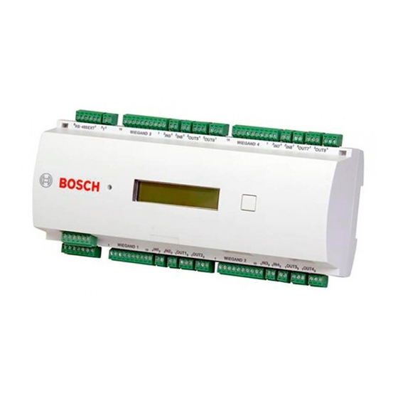
- Page 45 Access Modular Controller 2 Appendices | en Figure 7.3: Connector blocks of the AMC2-4W Bosch Security Systems B.V. Installation manual 2020-01 | V02 |...
- Page 46 For reader settings refer to the respective reader manual. Analog Input, in Analog Input, out Tab. 7.7: Analog input Relay Output, normally open Relay Output, common Relay Output, normally closed Tab. 7.8: Relay output 2020-01 | V02 | Installation manual Bosch Security Systems B.V.
- Page 47 Power supply for external devices (10V - 30V) Power supply for external devices (0V) Shield Data RxTx+ Data RxTx- Ground (PAG) Tab. 7.9: Host / Extension interface Tamper Contact, in Tamper Contact, out Tab. 7.10: External tamper contact Bosch Security Systems B.V. Installation manual 2020-01 | V02 |...
- Page 48 | Appendices Access Modular Controller 2 2020-01 | V02 | Installation manual Bosch Security Systems B.V.
- Page 49 Access Modular Controller 2 Appendices | en Bosch Security Systems B.V. Installation manual 2020-01 | V02 |...
-
Page 50: Index
11 power supply 16, 20 reader interfaces 11, 28, 40 Wiegand 28 resetting 38 resistor 32 RS-232 host interface 10, 25 RS-485 host interface 9, 10, 22 shielding 18 2020-01 | V02 | Installation manual Bosch Security Systems B.V. - Page 51 Access Modular Controller 2 Index | Bosch Security Systems B.V. Installation manual 2020-01 | V02 |...
- Page 52 | Index Access Modular Controller 2 2020-01 | V02 | Installation manual Bosch Security Systems B.V.
- Page 54 Bosch Security Systems B.V. Torenallee 49 5617 BA Eindhoven Netherlands www.boschsecurity.com © Bosch Security Systems B.V., 2020...