Table of Contents
Available languages
Available languages
Use & Care Guide
Manual de Uso y Cuidado
English / Español
Kenmore
®
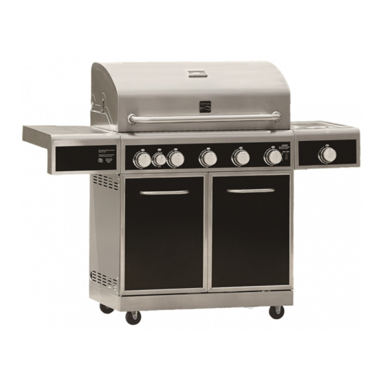
Liquid Propane Gas Grill
Parrilla a gas de propane liquido
Models/Modelos: 148.16156211-Black
148.20126510-Stainless Steel
Items / Artículos:
640-03838924-3-Negro
640-08668911-4-Acero Inoxidoble
P/N S3218N-Manual
Sears Brands Management Corporation
Hoffman Estates, IL 60179 U.S.A.
www.kenmore.com
www.sears.com
www.kmart.com
®
Chapters
Table of Contents

Related Manuals for Kenmore 148.16156211


Summary of Contents for Kenmore 148.16156211
- Page 1 Use & Care Guide Manual de Uso y Cuidado English / Español Kenmore ® Liquid Propane Gas Grill Parrilla a gas de propane liquido Models/Modelos: 148.16156211-Black 148.20126510-Stainless Steel Items / Artículos: 640-03838924-3-Negro 640-08668911-4-Acero Inoxidoble P/N S3218N-Manual Sears Brands Management Corporation Hoffman Estates, IL 60179 U.S.A.
-
Page 2: For Your Safety
Installation Safety Precautions • Use grill, as purchased, only with LP (propane) gas and the regulator/valve assembly supplied. A conversion kit must be purchased for use with natural gas. If you smell gas: • Grill installation must conform with local codes, or in their absence of local codes, with either the National Fuel Gas 1. -
Page 3: Table Of Contents
Installation Safety Precautions..... . . 2 Kenmore Grill Warranty......4 Use and Care. -
Page 4: Kenmore Grill Warranty
WARRANTY KENMORE LIMITED WARRANTY WITH PROOF OF SALE, the following warranty coverage applies when this appliance is correctly installed, operated and maintained according to all supplied instructions. To arrange for warranty service, call: 1-800-4-MY-HOME ® (1-800-469-4663) FOR ONE YEAR from the date of sale this appliance is warranted against defects in material or workmanship. A defective appliance will receive free repair or replacement at option of seller. -
Page 5: Use And Care
• Do not store an LP tank in an area where children play. USE AND CARE LP Cylinder • The LP cylinder used with your grill must meet the following requirements: • Use LP cylinders only with these required measurements: 12" (30.5cm) (diameter) x 18"... - Page 6 Connecting Regulator To The LP Tank LP Tank Exchange 1. LP tank must be properly secured onto grill. (Refer to •Many retailers that sell grills offer you the option of replacing assembly section.) your empty LP tank through an exchange service. Use only 2.
- Page 7 Leak Testing Valves, Hose and Regulator 1. Turn all grill control knobs to OFF. 2. Be sure regulator is tightly connected to LP tank. 3. Completely open LP tank valve by turning OPD hand wheel counterclockwise. If you hear a rushing sound, turn gas off Hold coupling nut and regulator immediately.
- Page 8 Safety Tips Before opening LP cylinder valve, check the coupling nut for tightness. When grill is not in use, turn off all control knobs and LP For Safe Use of Your Grill and to Avoid Serious cylinder valve. Injury: Never move grill while in operation or still hot. •...
- Page 9 5. If ignition does not occur in 5 seconds, turn the burner control off, wait 5 minutes for gas to clear away, and repeat the lighting procedure. 6. To light other burners, repeat step 4. NOTE: If ignitor does not work, follow Match Lighting instructions.
- Page 10 Do not use citrisol, abrasive cleaners, degreasers or a Storing Your Grill concentrated grill cleaner on plastic parts. Damage to and •Clean cooking grates. failure of parts can result. •Store in dry location. •Porcelain surfaces: Because of glass-like composition, most •When LP cylinder is connected to grill, store outdoors in a residue can be wiped away with baking soda/water solution or wellventilated space and out of reach of children.
- Page 11 VERY IMPORTANT: Burner tubes must reengage valve openings. Food Safety Food safety is a very important part of enjoying the outdoor cooking experience. To keep food safe from harmful bacteria, follow these four basic steps: Clean: Wash hands, utensils, and surfaces with hot soapy water before and after handling raw meat and poultry.
- Page 12 Gas Requirements Care and Maintenance Time Table Chart LP Gas If your grill is for LP Gas, the regulator supplied is set for Frequency Based Grill Item Cleaning Method on Normal Use an 11-in. water column (WC) and is for use with LP gas only.
-
Page 13: Transformer Connection Instruction
Push the transformer power cord through the opening in Transformer Connection Instruction the grill cart rear panel as shown, and plug it into an extension cord. To operate light, press the Main Light switch on the control panel to ON or OFF. For your convenience, this grill comes equipped with a UL approved transformer for outdoor use that provides low voltage to power 10-watt grill light featured with this... - Page 14 Make sure that the Main Light switch on the control Pull out the light bulb and replace with a new bulb. panel is pressed to OFF, and that transformer power Bulb cord is disconnected from power source. Use a screwdriver to loosen the screw holding the lens in place.
-
Page 15: Natural Gas Conversion Kit
Natural gas conversion kit 2. Insert plug and release sleeve. Kenmore Model # 10478 (Manufacturer Part No.: S3218AN-KIT) 3. Push plug until sleeve snaps forward. (Gas will flow automatically. Failure to connect plug properly to Natural gas nozzle 1.33mm for 16156/20126... -
Page 16: Parts List
PARTS LIST Manufacturer Manufacturer Key Qty Description Key Qty Description Part # Part # HOOD HANDLE 3218LT-00-4300 SWITCH E3520-00-8015 HANDLE BASE S3218ANR-00-4001 REAR BURNER BEZEL L3218-00-3002 HOOD S3218NB-00-4000 REAR BURNER KNOB L3218-00-3001 TEMPERATURE GAUGE 2818-2T-A300 IGNITION WIRE S3218ANR-00-8001 WASHER E3518-00-4009 47-1 CONTROL BOX (BLACK) S3218ANB-00-3101... -
Page 17: Parts Diagram
PARTS DIAGRAM ○ ○ ○ ○ ○ ○ ○ ○ ○ ○ ○ ○ ○ ○ ○ ○ ○ ○ ○ 20-1 ○ ○ ○ 17-2 17-1 ○ ○ ○ ○ ○ ○ 47-2 47-1 ○ 31-1 31-2 ○ ○ ○... -
Page 18: Assembly
UNPACKING After removing all parts and hardware pack from the top of the shipping box, and when the only part showing is the grill head, use a ox cutting knife to slice down the sides of the box. Be careful of staples along shipping box edges. - Page 19 Attach Rear Panel to Bottom Panel with 4 screws as shown. 1/4-20 x 5/8″Screw Qty. 4 Rear Panel Bottom Panel Attach side panels to bottom panel as shown. For each side panel, there are three screws for the rear panel and three for the bottom panel. Insert the three bottom panel screws first.. Rear Panel 1/4-20 x 5/8″Screw Qty.
- Page 20 Attach the side panel brackets to the side panels and bottom panel with 3 screws each as shown. 1/4-20 x 5/8″Screw Qty. 6 Left Panel Bottom Panel Right Panel Side Panel Bracket Slide the tank ring bracket onto the end of the tank ring as shown. Attach the bracket to the rear panel with 2 screws as shown.
- Page 21 Attach front beam to side panels with 2 screws on each side as shown. 1/4-20 x 5/8″Screw Qty. 4 Left Panel Front Beam Right Panel Remove the cap and the nut from the igniter. Secure the igniter and the igniter protective box to side panel with the nut. Then, reassemble the cap to the igniter.
- Page 22 Attach the drip cup support to the front beam and rear panel with 4 screws as shown. NOTE: Drip cup support tabs connect to outside of front beam. Drip Cup Support 1/4-20 x 5/8″Screw Qty. 4 Rear Panel Front Beam Put the drip cup on the drip cup support as shown.
- Page 23 Install the transformer to the rear panel with 4 each 5/32-32x3/8’’ screws and nuts. 5/32-32 x 3/8’’ Screw 5/32 Nut Qty. 4 Qty. 4 Install the LP tank exclusion rods, plain end to the bottom panel and nut end to the rear panel. 1/4-20 x 5/8’’...
- Page 24 Cut tie wraps holding regulator and side burner valve in place underneath grill head control panel. Be careful not to cut igniter wires or the tie wraps holding the igniter wires in place. With the aid of an assistant, lift and place grill head onto cart. Grill head sides go over attachment tabs on cart.
- Page 25 Side Burner Shelf Loosen the four screws attached in the right panel of the burner box 3 to 4 turns as shown. Hang the side burner shelf by the slotted holes in its side onto the four loosened screws. Open the grill lid and use the 1/4-20 x 1-1/4"...
- Page 26 Side Burner Tube Align side burner nozzle with side burner tube. Push nozzle onto tube. Secure nozzle to tube with two screws as shown. Replace the two side burner screws removed at the beginning of step 16. Place the side burner drip tray into position as shown. 5/32-32 x 3/16″Screw Qty.
- Page 27 Side Burner Ignition Pin Wire Run the side burner ignition pin wire into the cart and plug it into one of the narrow sockets in the igniter as shown. Ignition pin wire Ignition pin wire Connect here Other Ignition Wires Plug the six remaining narrow wire connectors into the remaining narrow igniter sockets, and plug the remaining wide connector into the remaining wide igniter socket.
- Page 28 For each door, insert bottom hinge pin into hole on bottom panel. Push down on top hinge pin to insert into hole in bottom corner of control panel. Adjust magnets on the bottom panel and front beam to align the magnets with doors, and then tighten magnet screws. Left Door Right Door Open the grill hood, cut the zip tie which hold the drip tray with the main burner.
- Page 29 Install the Heat Diffusers, Cooking Grates, Side Burner Grate and Warming Rack Position the heat diffusers, cooking grates, side burner grate and warming rack as shown. NOTE: The diffuser edges fit into slots at front and back of burner box. The rectangular hole in cooking grate goes to the front.
-
Page 30: Natural Gas Conversion Instructions
Follow the conversion instruction provided with the kit. 1.37mm 1.37mm 1.33mm 5 pc 1 pc 1 pc 148.16156211 Provided Provided Provided 148.20126510 in 10478 in 10478 with grill Main Burner Conversion 1. Remove the R pins at the back of main burners to detach burners from bracket. - Page 31 3. Put the new orifice into the orifice removal tool (B), and then insert the tool into the burner opening and tighten the new orifice into the valve. Repeat this step for all five burners. 1.37 Make sure you are using the correct orifice, which is marked “1.37”.
- Page 32 3. Tighten the new orifice to the valve. Make sure you are using the correct orifice, marked “1.37”. (Fig. 7) 1.37 Fig. 7 Rear Burner Conversion 1. Remove 5 screws (3/16-24 X 1/2 in.) at the back Rear burner of burner box to detach the rear burner cover cover from the rear panel of burner box.
- Page 33 3. Replace it with the NG orifice, and then tighten. Make sure you are using the correct orifice, marked “1.33”. This is the orifice that came with the grill. (Fig. 10) Rear burner 1.33 Fig. 10 4. Loosen the air shutter of the rear burner and adjust the distance between air shutter and rear burner.
- Page 34 Adjust valve control screw 1. Pull all the knobs off of valve stems. Adjust the screw in the valve hole using the flathead screwdriver. Turn screws two complete turns counterclockwise. (Fig. 13) Fig. 13 Valve hole 2. Press all the knobs back onto valve stems. 3.
-
Page 35: Troubleshooting
Troubleshooting Problem Possible Cause Corrective Action 1. The ignition wire came off 1. Reconnect the ignition wire to the the electrical igniter. electrical igniter. 2. The distance between the 2. Loosen the ignition pin and adjust the ignition pin and the burner distance, then fasten it again. - Page 36 Problem Possible Cause Corrective Action 1. LP tank is empty. 1. Refill the LP Tank. 2. Burner is not aligned with 2. Install the burner correctly. Burner blows out the control valve. 3. Gas supply is not sufficient. 3. Check the gas supply hose and make sure there are no leaks and no knots.
- Page 37 Problem Possible Cause Corrective Action The propane regulator Please follow these instructions: assembly incorporates an excess 1. Make sure all burners are “OFF”. flow device designed to supply the 2. Open the tank valve and wait 5 grill with sufficient gas flow. Rapid minutes.
-
Page 38: Para Su Seguridad
Precauciones de seguridad para la instalación • Utilice la parrilla, como la compró, sólo con gas LP (propano) y el ensamble de regulador/válvula que se suministra. Deberá comprar un kit de conversión para uso con gas natural. Si detecta olor a gas: •... - Page 39 1-800-4-MY-HOME Garantía de la parrilla Kenmore......40 Uso y cuidado........41-48 Instrucciones para la conexión del transformador.
-
Page 40: Garantía De La Parrilla Kenmore
GARANTÍA GARANTÍA LIMITADA DE KENMORE CON LA PRUEBA DE VENTA, el cubrimiento de la siguiente garantía se aplica cuando este equipo se instale, opere y reciba mantenimiento correctamente, de acuerdo a todas las instrucciones suministradas. Para solicitar el servicio de garantía, llame al: 1-800-4-MY-HOME... -
Page 41: Uso Y Cuidado
USO Y CUIDADO garaje, porche, patio cubierto u otro edificio. Nunca deje un tanque de LP dentro de un vehículo que pueda recalentarse con el sol. • No guarde un tanque de LP en un área donde jueguen los niños. Cilindro de LP •... - Page 42 de LP certificado más cercano. Intercambio del tanque LP Cómo conectar el regulador al tanque de LP • Muchos distribuidores que venden parrillas ofrecen la opción de 1. El tanque de LP deberá estar adecuadamente fijado a la reemplazar su tanque vacío de LP a través de un servicio de parrilla.
- Page 43 Válvulas para prueba de fugas, manguera y regulador 1. Gire todas las perillas de control de la parrilla a la posición OFF (cerrado). 2. Cerciórese de que el regulador esté conectado de forma bien ajustada al tanque de LP. Sostenga la tuerca de empalme y 3.
- Page 44 Consejos prácticos sobre seguridad Antes de abrir la válvula del cilindro de LP, verifique que la tuerca de acople esté bien apretada. Cuando la parrilla no esté en uso, cierre todas las perillas de Para el uso seguro de su parrilla y para evitar control y la válvula del cilindro LP.
- Page 45 5. Si no enciende en 5 segundos, apague el control del quemador, espere 5 minutos para que se disipe el gas y repita el procedimiento de encendido. 6. Para encender otros quemadores, repita el paso 4. NOTA: Si el encendedor no funciona, siga las instrucciones de encendido con fósforos.
- Page 46 deje secar completamente al aire. No aplique limpiador Almacenaje de la parrilla cáustico para parrilla/horno a las superficies pintadas. • Limpie las rejillas de cocción. • Partes plásticas: Lave con agua caliente jabonosa y seque. • Guarde en una ubicación seca. No utilice Citrisol, limpiadores abrasivos, desengrasadores ni •...
- Page 47 MUY IMPORTANTE: Los tubos del quemador deberán Seguridad alimentaria volverse a enganchar en las aberturas de las válvulas. La seguridad alimentaria es una parte muy importante de disfrutar la experiencia de cocinar al aire libre. Para conservar los alimentos protegidos de las bacterias nocivas, siga estos cuatro pasos básicos: Limpiar: Lávese las manos, los utensilios y superficies con agua caliente jabonosa antes y después de manipular carne o...
- Page 48 quemadores en la posición HI durante 15 minutos para Exigencias respecto de la conexión de gas realizar una autolimpieza quemando la grasa. Gas PL Si su parrilla funciona a gas PL, el regulador provisto Cuadro de tiempo de cuidado y mantenimiento está...
-
Page 49: Instrucciones Para La Conexión Del Transformador
Presione el cable eléctrico del transformador por la Instrucciones para la conexión del abertura del panel posterior del carrito de la parrilla, transformador como se muestra, y enchúfelo a una extensión eléctrica. Para hacer funcionar la luz, coloque el interruptor de luz Para su comodidad, esta parrilla está... - Page 50 Asegúrese de que el interruptor de de la lámpara en el panel de control esté en la posición “OFF” y que Retire la bombilla y reemplácela por una nueva. el enchufe esté desconectado del tomacorriente. Bombilla Utilice un destornillador para aflojar el tornillo que sujeta el panel posterior de la caja del quemador.
-
Page 51: Gas Natural Kit De Conversión
1,33 mm (incluida en la parrilla) son necesarias para la conversión. Kit de conversión a gas natural Modelo Kenmore # 10478 (No. de pieza del fabricante: S3218AN-KIT) 2. Inserte el tapón y libere el manguito. -
Page 52: Lista De Piezas
LISTA DE PIEZAS Pieza del Pieza del Clave Cant. Descripción Clave Cant. Descripción fabricante fabricante MANGUERA DEL QUEMADOR MANIJA DE LA CUBIERTA 3218LT-00-4300 P3018-00-8021 PRINCIPAL BASE DE LA MANIJA S3218ANR-00-4001 TUBO COLECTOR S3218ANR-00-3200 CUBIERTA S3218NB-00-4000 INTERRUPTOR E3520-00-8015 INDICADOR DE TEMPERATURA 2818-2T-A300 BISEL DEL QUEMADOR POSTERIOR L3218-00-3002... -
Page 53: Diagrama De Piezas
DIAGRAMA DE LAS PIEZAS ○ ○ ○ ○ ○ ○ ○ ○ ○ ○ ○ ○ ○ ○ ○ ○ ○ ○ ○ 20-1 ○ ○ ○ 17-2 17-1 ○ ○ ○ ○ ○ ○ 47-2 47-1 ○ 31-1 31-2 ○... -
Page 54: Ensamblaje
DESEMBALAJE Después de retirar todas las piezas y el paquete de aditamentos de la parte superior de la caja de transporte, y cuando la única sección que se muestre sea la parte principal de la parrilla, use un cuchillo para cortar cajas y deslícelo por los costados. - Page 55 Fije el panel posterior al panel inferior con 4 tornillos como se muestra. Tornillo de 1/4-20 x 5/8″ Cant. 4 Panel posterior Panel inferior Fije los paneles laterales al panel inferior como se muestra. Hay tres tornillos por cada panel lateral para el panel posterior y tres para el panel inferior.
- Page 56 Fije los soportes del panel lateral a los paneles laterales y al panel inferior con 3 tornillos cada uno como se muestra. Tornillo de 1/4-20 x 5/8” Cant. 6 Panel izquierda Panel inferior Panel derecho Soporte del panel lateral Deslice el soporte del anillo del tanque hacia el extremo del anillo del tanque como se muestra. Fije el soporte al panel posterior con 2 tornillos como se muestra.
- Page 57 Fije la luz frontal a los paneles laterales con 2 tornillos en cada lado como se muestra. Tornillo de 1/4-20 x 5/8” Cant. 4 Panel izquierda Barra frontal Panel derecho Retire la tapa y la tuerca del encendedor. Fije el encendedor y la caja protectora del encendedor al panel lateral con la tuerca. Luego, vuelva a colocar la tapa en el encendedor.
- Page 58 Fije el soporte de la bandeja de goteo a la viga frontal y al panel posterior con cuatro tornillos, como se muestra. NOTA: Las lengüetas del soporte de la bandeja de goteo se conectan con la parte exterior de la viga frontal.
- Page 59 Instale el transformador al panel posterior con 4 tornillos y tuercas de 5/32-32x3/8”. Tornillo de 5/32-32 x 3/8’’ 5/32 Tuerca Cant. 4 Cant. 4 Instale las varillas de exclusión del tanque de PL, el extremo simple al panel inferior y el extremo de la tuerca al panel posterior.
- Page 60 Corte las amarras que sostienen el regulador y la válvula del quemador lateral en su lugar debajo del panel de control de la parte principal de la parrilla. Tenga cuidado de no cortar cables del encendedor o las amarras que sostienen los cables del encendedor en su lugar. Con la ayuda de otra persona, levante y coloque la parte principal de la parrilla en el carrito.
- Page 61 Estante del quemador lateral Dé 3 a 4 vueltas para aflojar los cuatro tornillos fijados en el panel derecho de la caja del quemador. Cuelgue el estante del quemador lateral por los orificios ranurados en sus costados sobre los cuatro tornillos aflojados.
- Page 62 El tubo del quemador lateral Alinee la boquilla del quemador lateral con el tubo del quemador lateral. Presione la boquilla en el tubo. Asegure la boquilla al tubo con dos tornillos como se muestra. Reemplace los dos tornillos del quemador lateral que se retiraron el comienzo del paso 16. Coloque la bandeja de goteo del quemador lateral en la posición que se muestra.
- Page 63 Cable del pasador de encendido del quemador lateral Pase el cable del pasador de encendido del quemador lateral por el carrito y enchúfelo en uno de los tomacorrientes angostos del encendedor como se muestra. Cable del Cable del Conecte aquí encendido pasador encendido pasador Otros cables de encendido...
- Page 64 En cada puerta, inserte el pasador de la bisagra inferior en el orificio del panel inferior. Presione el pasador de bisagra superior para insertarlo en el orificio de la esquina inferior del panel de control. Ajuste los imanes en el panel inferior y en la viga frontal para alinear los imanes con las puertas, y luego apriete los tornillos para imanes.
- Page 65 Instale los difusores de calor, las rejillas de cocción y las rejillas para calentar Coloque los difusores de calor, las rejillas de cocción y las rejillas para calentar como se muestra. NOTA: Los bordes de los difusores encajan en las ranuras de la parte frontal y posterior de la caja del quemador.
-
Page 66: Instrucciones De Conversión De Gas Natural
Instrucciones de conversión de gas natural El kit de GN 10478 incluye orificios para varios modelos Modelo Quemador Quemador Quemador de parrilla. Seleccione los orificios según la lista que principal lateral posterior aparece a continuación y deseche el resto. Siga las 1.37mm 1.37mm 1.33mm... - Page 67 3. Coloque el nuevo orificio en la herramienta para eliminar orificios (B), luego inserte la herramienta en la abertura del quemador y apriete el nuevo orificio en la válvula. Repita este paso para los cinco quemadores. 1.37 Asegúrese de que está utilizando el orificio correcto, el cual está...
- Page 68 3. Apriete el nuevo orificio en la válvula. Asegúrese de que está utilizando el orificio correcto, marcado como “1,37”. (Fig. 7) 1.37 Fig. 7 Conversión del quemador posterior Retire 5 tornillos (3/16-24 X 1/2") de la parte Cubierta del quemador posterior de la caja del quemador para extraer posterior la cubierta del quemador posterior del panel o...
- Page 69 Reemplácelo con el orificio para gas natural y luego apriete. Asegúrese de que está utilizando el orificio correcto, marcado como “1,33”. (Fig. 10) Quemador posterior 1.33 Fig. 10 Afloje el obturador de aire del quemador posterior y ajuste la distancia entre el obturador y el quemador posterior.
- Page 70 Ajuste el tornillo de control de la válvula 1. Jale todas las perillas para retirarlas de los vástagos de las válvulas. Ajuste el tornillo del orificio de la válvula con el destornillador de cabeza plana (C). Tornillos de dos vueltas completas (720 °) hacia la izquierda.(Fig.
-
Page 71: Solución De Problemas
Solución de problemas Problema Causa posible Acción correctiva 1. El cable de encendido se 1. Vuelva a conectar el cable de encendido al desconectó del encendedor encendedor eléctrico. eléctrico. 2. Afloje el pasador y ajuste la distancia, luego 2. La distancia entre el pasador de vuelva a apretarlo. - Page 72 Problema Causa posible Acción correctiva 1. Los modelos a gas natural 1. Este modelo está configurado para utilizar generan poco calor. 177,80 mm de gas natural. Verifique su sistema de suministro de gas natural para 2. Los puertos están bloqueados. determinar si tiene una presión de gas correcta.
- Page 73 Problema Causa posible Acción correctiva 1. Se agotó el gas. 1. Verifique el nivel de gas en el cilindro de PL. 2. Se activó la válvula de exceso 2. Apague las perillas, espere 30 segundos y de flujo. encienda la parrilla. Si las llamas siguen bajas, apague las perillas y la válvula del cilindro de PL.
- Page 74 BA 美...