Table of Contents
Quick Links
Table of Contents

Related Manuals for Lenovo ideapad D330-10IGM


Summary of Contents for Lenovo ideapad D330-10IGM
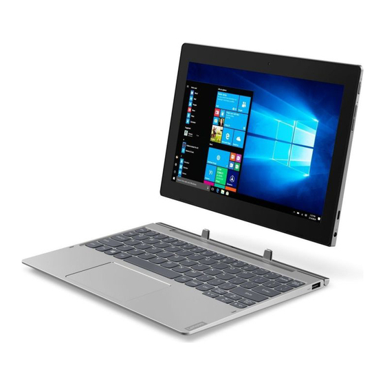
- Page 1 Lenovo ideapad D330-10IGM Hardware Maintenance Manual...
- Page 2 Note: • Before using this information and the product it supports, be sure to read the general information under “Notices” on page 59. First Edition (June 2018) © Copyright Lenovo 2018. All rights reserved. LIMITED AND RESTRICTED RIGHTS NOTICE: If data or software is delivered pursuant a General Services Administration “GSA” contract, use, reproduction, or disclosure is subject to restrictions set forth in Contract No. GS-35F-05925. © 2018 Lenovo...
-
Page 3: Table Of Contents
Passwords ............ 24 Power-on password ..........24 Hard-disk password ..........24 Administrator password ........24 Power management ........25 Screen blank state ..........25 Putting the computer to sleep or shutting it down ..............25 Putting your computer to sleep ......25 Shutting down the computer ......26 Lenovo ideapad D330-10IGM..... 27 Specifications ..........27 Function key combinations ......29 FRU replacement notices ......30 Screw notices ..........30 Removing and replacing an FRU ....31 1010 Tablet ............32 1020 Nano-SIM-card and microSD card tray ...33 1030 Tablet cover ..........34 1040 Battery pack ..........38 1050 PCI Express Mini Card for wireless LAN . -
Page 4: About This Manual
• The product-specific section includes service, reference, and product-specific parts information. Important: This manual is intended only for trained servicers who are familiar with Lenovo products. Use this manual to troubleshoot problems effectively. Before servicing a Lenovo product, make sure to read all the information under “Safety information” on page 1 and “Important service information” on page 16. -
Page 5: Safety Information
Safety information Safety information This chapter presents the following safety information that you need to get familiar with before you service a Lenovo ideapad D330-10IGM computer: • “General safety” on page 2 • “Electrical safety” on page 3 • “Safety inspection guide” on page 5 • “Handling devices that are sensitive to electrostatic discharge” on page 6 • “Grounding requirements” on page 6 • “Safety notices: multilingual translations” on page 7 • “Laser compliance statement” on page 14... -
Page 6: General Safety
Hardware Maintenance Manual General safety Follow these rules below to ensure general safety: • Observe a good housekeeping in the area where the machines are put during and after the maintenance. • When lifting any heavy object: 1. Make sure that you can stand safely without slipping. 2. Distribute the weight of the object equally between your feet. 3. Use a slow lifting force. Never move suddenly or twist when you attempt to lift it. 4. Lift it by standing or pushing up with your leg muscles; this action could avoid the strain from the muscles in your back. Do not attempt to lift any object that weighs more than 16 kg (35 lb) or that you think is too heavy for you. • Do not perform any action that causes hazards to the customer, or that makes the machine unsafe. -
Page 7: Electrical Safety
Safety information Safety information Electrical safety Observe the following rules when working on electrical equipments. Important: Use only approved tools and test equipments. Some hand tools have handles covered with a soft material that does not insulate you when working with live electrical currents. Many customers have rubber floor mats near their machines that contain small conductive fibers to decrease electrostatic discharges. - Page 8 Hardware Maintenance Manual • Always look carefully for possible hazards in your work area. Examples of these hazards are moist floors, nongrounded power extension cables, power surges, and missing safety grounds. • Do not touch live electrical circuits with the reflective surface of a plastic dental mirror. The surface is conductive; such touching can cause personal injury and machine damage. • Do not service the following parts with the power on when they are removed from their normal operating places in a machine: – Power supply units – Pumps – Blowers and fans – Motor generators and similar units. (This practice ensures correct grounding of the units.) • If an electrical accident occurs: – Caution: do not become a victim yourself. – Switch off the power. – Send the victim to get medical aid.
-
Page 9: Safety Inspection Guide
The power cord should be the type specified in the parts list. c. Insulation must not be frayed or worn. 4. Check for cracked or bulging batteries. 5. Remove the cover. 6. Check for any obvious non-Lenovo alterations. Use good judgment as to the safety of any non-Lenovo alterations. 7. Check inside the unit for any obvious unsafe conditions, such as metal filings, contamination, water or other liquids, or signs of fire or smoke damage. 8. Check for worn, frayed, or pinched cables. -
Page 10: Handling Devices That Are Sensitive To Electrostatic Discharge
Hardware Maintenance Manual Handling devices that are sensitive to electrostatic discharge Any computer part containing transistors or integrated circuits (ICs) should be considered sensitive to electrostatic discharge (ESD). ESD damage can occur when there is a difference in charge between objects. Protect against ESD damage by equalizing the charge so that the machine, the part, the work mat, and the person handling the part are all at the same charge. Notes: 1. Use product-specific ESD procedures when they exceed the requirements noted here. 2. -
Page 11: Safety Notices: Multilingual Translations
Safety information Safety notices: multilingual translations The safety notices in this section are provided in English, French, German, Hebrew, Italian, Japanese, and Spanish. Safety notice 1 Before the computer is powered on after FRU replacement, make sure all screws, springs, and other small parts are in place and are not left loose inside the computer. Verify this by shaking the computer and listening for rattling sounds. - Page 12 Hardware Maintenance Manual Safety notice 2 DANGER Some standby batteries contain a small amount of nickel and cadmium. Do not disassemble a standby battery, recharge it, throw it into fire or water, or short- circuit it. Dispose of the battery as required by local ordinances or regulations. Use only the battery in the appropriate parts listing.
- Page 13 Safety information Safety notice 3 DANGER The battery pack contains small amounts of nickel. Do not disassemble it, throw it into fire or water, or short-circuit it. Dispose of the battery pack as required by local ordinances or regulations. Use only the battery in the appropriate parts listing when replacing the battery pack.
- Page 14 Hardware Maintenance Manual Safety notice 4 DANGER The lithium battery can cause a fire, an explosion, or a severe burn. Do not recharge it, remove its polarized connector, disassemble it, heat it above 100°C (212°F), incinerate it, or expose its cell contents to water. Dispose of the battery as required by local ordinances or regulations.
- Page 15 Safety information Safety notice 5 If the LCD breaks and the fluid from inside the LCD gets into your eyes or on your hands, immediately wash the affected areas with water at least for 15 minutes. Seek medical care if any symptoms caused by the fluid are present after washing. Si le panneau d’affichage à...
- Page 16 Hardware Maintenance Manual Safety notice 6 DANGER To avoid shock, do not remove the plastic cover that protects the lower part of the inverter card. Afin d’éviter tout risque de choc électrique, ne retirez pas le cache en plastique protégeant la partie inférieure de la carte d’alimentation. Aus Sicherheitsgründen die Kunststoffabdeckung, die den unteren Teil der Spannungswandlerplatine umgibt, nicht entfernen.
- Page 17 Safety information Safety notice 8 DANGER Before removing any FRU, turn off the computer, unplug all power cords from electrical outlets, remove the battery pack, and then disconnect any interconnecting cables. Avant de retirer une unité remplaçable en clientèle, mettez le système hors tension, débranchez tous les cordons d’alimentation des socles de prise de courant, retirez la batterie et déconnectez tous les cordons d’interface.
-
Page 18: Laser Compliance Statement
Hardware Maintenance Manual Laser compliance statement Some models of Lenovo computer are equipped from the factory with an optical storage device such as a CD-ROM drive or a DVD-ROM drive. Such devices are also sold separately as options. If one of these drives is installed, it is certified in the U.S. to conform to the requirements of the Department of Health and Human Services 21 Code of Federal Regulations (DHHS 21 CFR) Subchapter J for Class 1 laser products. Elsewhere, the drive is certified to conform to the requirements of the International Electrotechnical Commission (IEC) 825 and CENELEC EN 60 825 for Class 1 laser products. - Page 19 Safety information A CD-ROM drive, a DVD-ROM drive, or any other storage device installed may contain an embedded Class 3A or Class 3B laser diode. Note the following: DANGER Emits visible and invisible laser radiation when open. Do not stare into the beam, do not view directly with optical instruments, and avoid direct exposure to the beam. Radiação por raio laser ao abrir. Não olhe fixo no feixe de luz, não olhe diretamente por meio de instrumentos óticos e evite exposição direta com o feixe de luz.
-
Page 20: Important Service Information
Strategy for replacing FRUs Before replacing parts: Make sure that all software fixes, drivers, and BIOS downloads are installed before replacing any FRUs listed in this manual. After a system board is replaced, ensure that the latest BIOS is loaded to the system board before completing the service action. To download software fixes, drivers, and BIOS, follow the steps below: 1. Go to http://support.lenovo.com. 2. Enter the serial number or select a product or use Lenovo smart downloading. 3. Select the BIOS/Driver/Applications and download. 4. Follow the directions on the screen and install the necessary software. -
Page 21: Strategy For Replacing A Hard Disk Drive
Important service information Use the following strategy to prevent unnecessary expense for replacing and servicing FRUs: • If you are instructed to replace an FRU, but the replacement does not solve the problem, reinstall the original FRU before you continue. • Some computers have both a processor board and a system board. If you are instructed to replace either of them, and replacing one of them does not solve the problem, reinstall that board, and then replace the other one. • If an adapter or a device consists of more than one FRU, any of the FRUs may be the cause of the error. Before replacing the adapter or device, remove the FRUs one by one to see if the symptoms change. Replace only the FRU that changed the symptoms. Attention: The setup configuration on the computer you are servicing may have been customized. Running Automatic Configuration may alter the settings. Note the current configuration settings (using the View Configuration option); then, when service has been completed, verify that those settings remain in effect. -
Page 22: Important Information About Replacing Rohs Compliant Frus
Electronic Equipment Directive (2002/95/EC) is a European Union legal requirement affecting the global electronics industry. RoHS requirements must be implemented on Lenovo products placed on the market after June 2006. Products on the market before June 2006 are not required to have RoHS compliant parts. -
Page 23: General Checkout
General checkout General checkout This chapter presents the following information: • “What to do first” on page 20 • “Power system checkout” on page 21 Before you go to the checkout, make sure to read the following important notes: Important notes: • Only certified trained personnel can service the computer. • Before replacing any FRU, read the entire page on removing and replacing FRUs. • Carefully remove screws for reuse when replacing FRUs. • Be extremely careful during such write operations as copying, saving, or formatting. Drives in the computer that you are servicing sequence might have been altered. -
Page 24: What To Do First
Hardware Maintenance Manual What to do first When you do return an FRU, you must include the following information in the parts exchange form or parts return form that you attach to it: 1. Name and phone number of servicer 2. Date of service 3. Date on which the machine failed 4. Date of purchase 5. Procedure index and page number in which the failing FRU was detected 6. Failing FRU name and part number 7. Machine type, model number, and serial number 8. Customer’s name and address Note for warranty: During the warranty period, the customer may be responsible for repair costs if the computer damage was caused by misuse, accident, modification, unsuitable physical or operating environment, or improper maintenance by the customer. -
Page 25: Power System Checkout
To check the AC adapter, follow the steps below: 1. Unplug the AC adapter cable from the computer. 2. Measure the output voltage at the plug of the AC adapter cable. See the following figure: Voltage (V DC) Current (A DC) 2.25 Note: Output voltage for the AC adapter pin No. 2 may differ from the one you are servicing. 3. If the voltage is not correct, replace the AC adapter. 4. If the voltage is acceptable, do the following: • Replace the system board. • If the problem persists, go to “Lenovo ideapad D330-10IGM” on page 27. Note: Noise from the AC adapter does not always indicate a defect. Checking operational charging To check whether the battery charges properly during operation, use a discharged battery pack or a battery pack that has less than 50% of the total power remaining when installed in the computer. -
Page 26: Checking The Battery Pack
Hardware Maintenance Manual Perform operational charging. If the battery status indicator or icon does not light on, remove the battery pack and let it return to room temperature. Reinstall the battery pack. If the charge indicator or icon is still off, replace the battery pack. If the charge indicator still does not light on, replace the system board. Then reinstall the battery pack. If it is still not charged, go to the next section. Checking the battery pack Battery charging does not start until the Power Meter shows that less than 95% of the total power remains; under this condition the battery pack can charge to 100% of its capacity. This protects the battery pack from being overcharged or from having a shortened life. To check your battery, move your cursor to the Power Meter icon in the icon ® tray of the Windows taskbar and wait for a moment (but do not click it), and the percentage of battery power remaining is displayed. To get detailed information about the battery, double-click the Power Meter icon. Note: If the battery pack becomes hot, it may not be able to be charged. Remove it from the computer and leave it at room temperature for a while. After it cools down, reinstall and recharge it. -
Page 27: Related Service Information
This chapter presents the following information: • “Restoring the factory contents by using OneKey Recovery” on page 23 • “Passwords” on page 24 • “Power management” on page 25 Restoring the factory contents by using Push-button reset Restore of factory default The Lenovo ideapad D330-10IGM computers come with pre-installed Push- button reset. In order to save application files and the initial backed up files of the system, the hard disk in a Lenovo computer includes a hidden partition when it is shipped. If you need to restore the system to the point of your first boot up, press the Novo button and run System Recovery. For details of Push-button reset, see the Recovery system in the User Guide. Note: This will delete all the new data on the system partition (C drive), which is not recoverable. -
Page 28: Passwords
Hardware Maintenance Manual Passwords As many as three passwords may be needed for any Lenovo computer: the power-on password (POP), the hard disk password (HDP), and the administrator password. If any of these passwords has been set, a prompt for it appears on the screen whenever the computer is turned on. The computer does not start until the password is entered. -
Page 29: Power Management
Related service information Power management Note: Power management modes are not supported for APM operating system. To reduce power consumption, the computer has three power management modes: screen blank, sleep (standby), and hibernation. Screen blank state If the time set on the “Turn off monitor” timer in the operating system expires, the LCD backlight turns off. To end screen blank state and resume normal operation, press any key on the keyboard or press the power button Putting the computer to sleep or shutting it down When you have finished working with your computer, you can put it to sleep or shut it down. -
Page 30: Shutting Down The Computer
Hardware Maintenance Manual Shutting down the computer If you are not going to use your computer for a long time, shut it down. To shut down your computer, do one of the following: • Select the Start button , then select Power → Shut down. • Right-click or press the Start button in the lower-left corner and select Shut down or sign out → Shut down. -
Page 31: Lenovo Ideapad D330-10Igm
Lenovo ideapad D330-10IGM Lenovo ideapad D330-10IGM This chapter presents the following product-specific service references and product-specific parts information: • “Specifications” on page 27 • “Function key combinations” on page 29 • “FRU replacement notices” on page 30 • “Removing and replacing an FRU” on page 31 • “Locations” on page 49 • “Parts list” on page 52 Specifications The following table lists the specifications of the Lenovo ideapad D330-10IGM: Table 1. Specifications Form Factor Dimensions Appr. 249 mm × 178 mm × 9.5 mm Weight Appr. 610g (Tablet) / 535g (Dock) LCD size 10.1-inch... - Page 32 Hardware Maintenance Manual Table 1. Specifications (continued) AC power adapter Input 100-240 V, 50-60 Hz O utput voltage 20 V DC Power 45 W Miscellaneous Camera...
-
Page 33: Function Key Combinations
Lenovo ideapad D330-10IGM Function key combinations Through the use of the function keys, you can change operational features instantly. Table 2. Function key combinations Increases the volume Fn + Mutes/unmutes the sound. Fn + level. Closes the currently active Activates the break Fn + Fn + window. function. Enables/disables the Activates the pause Fn + Fn + touchpad. -
Page 34: Fru Replacement Notices
Hardware Maintenance Manual FRU replacement notices This section presents notices related to removing and replacing parts. Read this section carefully before replacing any FRU. Screw notices Loose screws can cause a reliability problem. In the Lenovo computer, this problem is addressed with special nylon-coated screws that have the following characteristics: • They maintain tight connections. • They do not easily come loose, even with shock or vibration. • They are harder to tighten. -
Page 35: Removing And Replacing An Fru
Lenovo ideapad D330-10IGM Removing and replacing an FRU This section presents exploded figures with the instructions to indicate how to remove and replace the FRU. Make sure to observe the following general rules: 1. Do not attempt to service any computer unless you have been trained and certified. An untrained person runs the risk of damaging parts. 2. Before replacing any FRU, review “FRU replacement notices” on page 30. 3. Begin by removing any FRUs that have to be removed before the failing FRU. Any of such FRUs are listed at the top of the page. Remove them in the order in which they are listed. 4. Follow the correct sequence in the steps to remove the FRU, as given in the figures by the numbers in square callouts. 5. When turning a screw to replace an FRU, turn it in the direction as given by the arrow in the figure. 6. When removing the FRU, move it in the direction as given by the arrow in the figure. -
Page 36: 1010 Tablet
Hardware Maintenance Manual 1010 Tablet Figure 1. Removal steps of tablet Detach the tablet in the direction shown by the arrow 1. Note: Be careful not to damage the connector when attaching or detaching the tablet. -
Page 37: 1020 Nano-Sim-Card And Microsd Card Tray
Lenovo ideapad D330-10IGM 1020 Nano-SIM-card and microSD card tray For access, remove this FRU: • “1010 Tablet” on page 32 Figure 2. Removal steps of Nano-SIM-card and microSD card tray Insert a prying pin into the hole on the card tray and push it straight in until the card tray pops out. Pull out the card tray. -
Page 38: 1030 Tablet Cover
Hardware Maintenance Manual 1030 Tablet cover For access, remove this FRU: • “1010 Tablet” on page 32 • “1020 Nano-SIM-card and microSD card tray” on page 33 Figure 3. Removal steps of tablet cover Turn over the tablet. Insert a prying tool to separate the tablet cover from the tablet in the directions shown by arrows 1. Then remove the tablet cover in the direction shown by arrow 2. Note: Be careful when separating the tablet cover. Do not force apart the tablet cover. Otherwise, the tablet could be damaged. - Page 39 Lenovo ideapad D330-10IGM Note: Applying labels to the cover The new cover FRU is shipped with a kit containing labels of several kinds. When you replace the cover, you need to apply the following labels: The following labels need to be peeled off from the old cover and put on the new cover. Print label Windows label QR label BIS label KCC WL&BT label Argentina label Argentina label TW vision warning label Indonesia rating label Indonesia WL&BT Certificate label Israel label or US/CA/TW/RF Label South African ICASA Label MC Label SN label IMEI label intel label 8S label for Docking For some models, you also need to apply one or two FCC labels. Check the old cover; if it has one or two FCC labels, find duplicates of them in the label kit and apply them to the new cover. For the location of each label, refer to the following figures: Tablet...
- Page 40 Hardware Maintenance Manual For Wi-Fi For LTE (on select models)
- Page 41 Lenovo ideapad D330-10IGM Keyboard dock (on select models) For WW with WLAN Without WWAN For WW with WLAN With WWAN For China For India...
-
Page 42: 1040 Battery Pack
Hardware Maintenance Manual 1040 Battery pack DANGER Only use the battery specified in the parts list for your computer. Any other battery could ignite or explode. For access, remove this FRU: • “1010 Tablet” on page 32 • “1020 Nano-SIM-card and microSD card tray” on page 33 • “1030 Tablet cover” on page 34 Figure 4. Removal steps of battery pack Disconnect the audio card connector in the direction shown by arrow 1. - Page 43 Lenovo ideapad D330-10IGM Step Screw (quantity) Color M2.0*2mm_0.5mm_7mm, Phillips-head (1) Black Disconnect the battery pack connector in the direction shown by arrow 4. Remove the screws 5. Step Screw (quantity) Color M2.0*2mm_0.5mm_7mm, Phillips-head (3) Black Remove the battery pack in the direction shown by arrow 6. When installing: Make sure that the connector is attached firmly.
-
Page 44: 1050 Pci Express Mini Card For Wireless Lan
• “1040 Battery pack” on page 38 Important: The preinstalled WLAN module may only be replaced with a Lenovo approved module in order to comply with FCC and IC regulations. Refer to Table 3 “Parts list—Overall” on page 53 for Lenovo part numbers for the approved modules. - Page 45 Lenovo ideapad D330-10IGM Figure 5. Removal steps of PCI Express Mini Card for wireless LAN (continued) Remove the screw 2. Then remove the card in the direction shown by arrow 3. Step Screw (quantity) Color M2.0*2mm_0.5mm_5mm, Phillips-head (1) Black When installing: • In models that has two antenna connectors, plug the orange cable (1st) into the jack labeled MAIN, and the blue cable (2nd) into the jack labeled AUX on the card. • Make sure that the connectors are attached firmly and that you do not pinch the antenna cables when you attach the LCD assembly.
-
Page 46: 1060 Pogo Pin
Hardware Maintenance Manual 1060 Pogo pin For access, remove these FRUs in order: • “1030 Tablet cover” on page 34 • “1040 Battery pack” on page 38 • “1050 PCI Express Mini Card for wireless LAN” on page 40 • “1040 Battery pack” on page 38 • “1050 PCI Express Mini Card for wireless LAN” on page 40 Figure 4. Removal steps of pogo pin Disconnect the pogo pin connector in the direction shown by arrow A. Remove the screws 2. Then remove the pogo pin in the direction shown by arrow 3. Step Screw (quantity) Color M2.0*L3.0*D3.5*T0.5*3mm_0.5mm_2mm, Phillips-head (2) Silver... -
Page 47: 1070 System Board
Lenovo ideapad D330-10IGM 1070 System board Important notices for handling the system board: When handling the system board, bear the following in mind. • Be careful not to drop the system board on a bench top that has a hard surface, such as metal, wood, or composite. - Page 48 Hardware Maintenance Manual Figure 7. Removal steps of system board (continued) Remove the screws 4. Step Screw (quantity) Color M2.0*L3.0*D3.5*T0.5*3mm_0.5mm_2mm, Phillips-head (8) Silver Remove the thermal module in the direction shown by arrow 5.
- Page 49 Lenovo ideapad D330-10IGM Figure 7. Removal steps of system board (continued) Disconnect the connectors in the directions shown by arrows 6 to 8. Remove the system board in the direction shown by arrow 9. When installing: Make sure that the connectors are attached firmly and that you do not pinch the antenna cables when you attach the LCD assembly.
-
Page 50: 1080 Audio Card
Hardware Maintenance Manual 1080 Audio card For access, remove these FRUs in order: • “1010 Tablet” on page 32 • “1020 Nano-SIM-card and microSD card tray” on page 33 • “1030 Tablet cover” on page 34 • “1040 Battery pack” on page 38 • “1050 PCI Express Mini Card for wireless LAN” on page 40 • “1060 Pogo pin” on page 42 • “1070 System board” on page 43 Figure 8. Removal steps of audio card Remove the screws 1. Then remove the audio card in the direction shown by arrow 2. Step Screw (quantity) Color M2.0*L3.0*D3.5*T0.5*3mm_0.5mm_2mm, Phillips-head (2) Silver... -
Page 51: 1090 Speakers, Front And Rear Cameras, Power Button Fpc And Lcd Cable
Lenovo ideapad D330-10IGM 1090 Speakers, front and rear cameras, power button FPC and LCD cable For access, remove these FRUs in order: • “1010 Tablet” on page 32 • “1020 Nano-SIM-card and microSD card tray” on page 33 • “1030 Tablet cover” on page 34 • “1040 Battery pack” on page 38 • “1050 PCI Express Mini Card for wireless LAN” on page 40 • “1060 Pogo pin” on page 42 • “1070 System board” on page 43 • “1080 Rubber foot” on page 46 Figure 9. Removal steps of Speakers, front and rear cameras, and LCD cable Remove the speakers, the front and rear cameras, and power button FPC in the directions by arrows 1 2 3 and 4. - Page 52 Hardware Maintenance Manual Figure 9. Removal steps of Speakers, front and rear cameras, and LCD cable (continued) Disconnect the LCD cable connector in the direction shown by arrow 5. Then remove the LCD cable in the direction shown by arrow 6. When installing: Make sure that the connectors are attached firmly.
-
Page 53: Locations
Lenovo ideapad D330-10IGM Locations Front and right-side view of tablet 1 Front camera 2 Wireless LAN antennas 3 Wireless WAN antennas (on select models) 4 Multi-touch screen 5 Speaker 6 Tablet-keyboard dock latch 7 Keyboard dock connector 8 Nano-SIM-card and microSD card tray J AC power adapter jack K Type-C port L Volume up/down button M Power button... -
Page 54: Bottom And Left-Side View Of Tablet
Hardware Maintenance Manual Bottom and left-side view of tablet 1 Rear camera (on select models) 2 Combo audio jack Front and right-side view of keyboard dock 1 Tablet-keyboard dock latch 2 Keyboard dock connector 3 Touch pad 3 USB 2.0 port... -
Page 55: Bottom And Left-Side View Of Keyboard Dock
Lenovo ideapad D330-10IGM Bottom and left-side view of keyboard dock 1 USB 2.0 port... -
Page 56: Parts List
Hardware Maintenance Manual Parts list This section presents the following service parts: • “Overall” on page 53 • “Miscellaneous parts” on page 57 • “AC adapters” on page 57 • “Screws” on page 58 Note: Each FRU is available for all types or models, unless specific types or models are specified. Attention: Do not attempt to replace an FRU on your own. If an FRU is damaged, contact a Lenovo authorized servicer or a marketing representative for replacement or repair. Only qualified technicians can inspect or repair this product. -
Page 57: Overall
Lenovo ideapad D330-10IGM Overall... - Page 58 Hardware Maintenance Manual Table 3. Parts list—Overall FRU no. LCD MODULE H 81H3 10 FHD wifi 5D10R54664 LCD MODULE H 81H3 10 HD wifi 5D10R54672 LCD MODULE H 81H3 10 FHD LTE 5D10R54712 LCD MODULE H 81H3 10 HD LTE 5D10R54716 Audio board H 81H3 W/FFC 5A50R54660 LCD Cable H 81H3 FHD 5C10R54714 LCD Cable H 81H3 HD 5C10R54679 SP/A L17M2PF3 7.68V39Wh2cell 5B10Q93737 SD/A L17D2PF2 7.68V39Wh2cell 5B10Q93736 CP/C L17C2PF1 7.7V39Wh2cell 5B10Q93738 Pogo Pin FPC H 81H3 5C10R54681 Speaker H 81H3 L+R 5SB0R54675 LCD Cover H 81H3 MGR 2M 5CB0R54709 LCD Cover H 81H3 MGR 2M/5M 5CB0R54698 LCD Cover H 81H3 BZ 2M/5M 5CB0R54695 LCD Cover H 81H3 BZ 2M 5CB0R54692 Card Tray TF&SIM BZ H 81H3 5M20S13638...
- Page 59 Lenovo ideapad D330-10IGM Table 3. Parts list—Overall (continued) FRU no. D330 docking MGR GRE 5D20R49337 D330 docking BZ RUS 5D20R49336 D330 docking MGR FRA ENG 5D20R49385 D330 docking BZ TC 5D20R49335 D330 docking MGR EURO ENG 5D20R49384 D330 docking MGR NORDIC 5D20R49372 D330 docking MGR HIN 5D20R49371 D330 docking MGR FRA 5D20R49355 D330 docking BZ FRA 5D20R49354 D330 docking MGR THAI 5D20R49353 D330 docking BZ KOR 5D20R49332 D330 docking BZ ARA 5D20R49349 D330 docking BZ BUL 5D20R49388 D330 docking MGR BEL 5D20R49348 D330 docking MGR FRA/ARA 5D20R49387...
- Page 60 Hardware Maintenance Manual Table 3. Parts list—Overall (continued) FRU no. MB H81H3N5000128G4GW2X22M 5B20R54661 MB H81H3N400032G2GW1X1LTE2M 5B20R54674 MB H 81H3 N4000 128G 4GW1X12M 5B20R54659 MBH81H3N500064G4GW1X12MPD 5B20R61006 MB81H3N400032G2GW1X1LTE2M/5MPD 5B20R54694 MBH81H3N500064G4GW1X12M 5B20R61005 MB H81H3N400064G4GW1X1LTE2M 5B20R54693 MBH81H3N400032G2GW1X12M/5M 5B20R54688 MB H81H3N5000128G4GW2X2LTE2M 5B20R54687 MBH81H3N400032G2GW1X1LTE2M/5M 5B20R54713 MBH81H3N500064G4GW1X12M/5MPD 5B20R61001 MBH81H3N400032G2GW1X12M/5MPD 5B20R54711 MB81H3N5000128G4GW2X2LTE2M5MPD 5B20R54707 MBH81H3N500064G4GW1X1LTE2MPD 5B20R61002 MBH81H3N4000128G4GW1X1LTE2M 5B20R54680 MBH81H3N400064G4GW1X1LTE2M/5M 5B20R54677 MBH81H3N400032G4GW1X12MPD...
-
Page 61: Miscellaneous Parts
Lenovo ideapad D330-10IGM Miscellaneous parts Table 4. Parts list—Miscellaneous parts FRU no. System miscellaneous parts: SHIELDCAMERA_ECsheildingH81H3 • (a)5S60R54666 Sponge 12*12*0.05 81H3 • (b)5T10R54685 Sponge 28*16*0.05 81H3 • (b)5T10S13641 Sponge 24*24*0.05 81H3 • (b)5T10S13639 Note: Letters in parentheses are references to the exploded view in “Overall” on page 53. AC adapters Table 5. Parts list—AC adapters PA-1450-55LR 20V2.25A COO 01FR122 ADL45WCK 20V2.25A COO 01FR130 PA-1450-55LS 20V2.25A COO... -
Page 62: Screws
Hardware Maintenance Manual Table 5. Parts list—AC adapters (continued) VOLEX AU10S3+H03VV-F+VAC5S 1m cord 145000532 VOLEX GB10S3+RVV 300/500+VAC5S 1m cord 145000538 Longwell LP-30B+SPT-2 18AWG+LS-181mcord 145000562 VOLEX MP5004+H03VV-F+VAC5S 1m cord 145000605 Longwell LP-41+H03VV-F+LS-18 1m cord 145000563 VOLEX VA2073+H03VV-F+VAC5S 1m cord 145000528 Longwell LP-54+VCTF+LS-18 1m cord 145000555 VOLEX SI16S3+H03VV-F+VAC5S 1m cord 145000526 Longwell LP-67+BIS+LS-18 1m cord 145000560 Longwell LP-34A+H03VV-F+LS-18 1m cord 145000553 Longwell LP-39+H03VV-F+LS-18 1m cord 145000554 Longwell LP-24+H03VV-F+LS-18 1m cord 145000567 Longwell LP-486+KTLH03VV-F+LS-5 1m cord 145000558 Longwell LSG-31+RVV300/300+LS-18 1mcord 145000568 VOLEX M2511+HO3VV-F+VAC5S 1m cord 145000525 Longwell LP-22+H03VV-F+LS-18 1m cord 145000559 Longwell LP-23A+LFC-3R+LS-18 1m cord 145000557... -
Page 63: Notices
Notices Notices Lenovo may not offer the products, services, or features discussed in this document in all countries. Consult your local Lenovo representative for information on the products and services currently available in your area. Any reference to a Lenovo product, program, or service is not intended to state or imply that only that Lenovo product, program, or service may be used. Any functionally equivalent product, program, or service that does not infringe any Lenovo intellectual property right may be used instead. However, it is the... -
Page 64: Trademarks
Users of this document should verify the applicable data for their specific environment. Trademarks LENOVO, LENOVO logo, IDEAPAD and the IDEAPAD logo are trademarks of Lenovo. Microsoft, Windows and Cortana are trademarks of the Microsoft group of companies. The terms HDMI and HDMI High-Definition Multimedia Interface are trademarks or registered trademarks of HDMI Licensing LLC in the United States and other countries. All other trademarks are the property of...