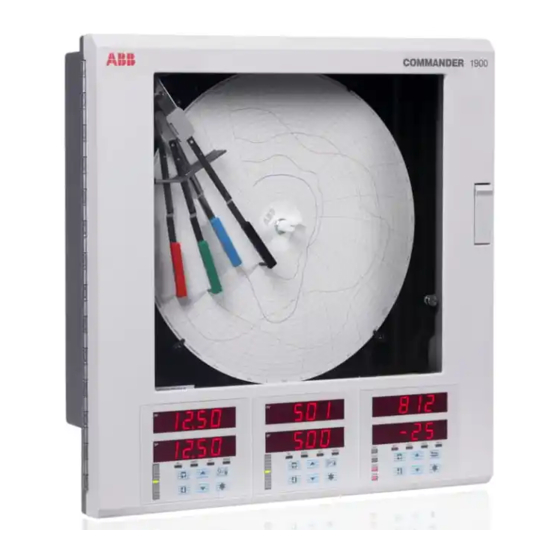
ABB C1900 Installation Manual
Circular chart recorder and recorder/controller
Hide thumbs
Also See for C1900:
- Operating manual (44 pages) ,
- Installation manual (28 pages) ,
- User manual (20 pages)

Related Manuals for ABB C1900


Summary of Contents for ABB C1900
- Page 1 Installation Guide Inform IM/C1900–INS_8 Circular Chart Recorder and Recorder/Controller C1900...
- Page 2 Cert. No. Q 05907 As a part of ABB, a world leader in process automation technology, we offer customers application expertise, service and support worldwide. EN 29001 (ISO 9001) We are committed to teamwork, high quality manufacturing, advanced technology and unrivalled service and support.
-
Page 3: Table Of Contents
Electrical Connections 4.2.3 2-wire Transmitter Input ...... 7 Installation Record 4.2.4 Thermocouple ........7 Part No. Part No. IM/C1900–INS SS C1900 4.2.5 Resistance Thermometer (RTD) ..7 4.2.6 Logic Inputs ........7 4.2.7 Analog Output ........7 Recorders and Controllers 4.2.8 Relay Output ........ -
Page 4: Preparation
Pull handle to release (part no. C1900/0712) door... Check code number against the Specification Sheet – C – DIN Rail (part no. C1900/0713) SS/C1900R or SS/C1900RC Loosen captive screw Swing chart plate forward D – Optional Case-to-Panel Gasket ...and open door (part no. -
Page 5: Mechanical Installation
3 MECHANICAL INSTALLATION 3.1 Siting – Figs 3.1 and 3.2 3.2 Mounting – Figs. 3.3 to 3.5 Dimensions in inches (mm) Minimum Sensor 15.04 (382) A – Close to Sensor 15.23 (386.8) B – At Eye-level Location C – Avoid Vibration 1.30 (33) 2.60 (66) Fig. -
Page 6: Wall-/Pipe-Mounting
...3 MECHANICAL INSTALLATION 3.2.1 Wall-/Pipe-Mounting – Fig. 3.4 3.2.2 Panel Mounting – Fig. 3.5 Dimensions in inches (mm) in – 28 UNF 4 holes 0.281 dia. studs into case or tap for in thread Mark four mounting holes Secure mounting 14.00 (355.6) brackets to case 12.72 (323.08) -
Page 7: Electrical Installation
4 ELECTRICAL INSTALLATION 4.1 Identifying the Input/Output Modules – Fig. 4.2 Warning. Before making any connections, ensure that the To gain access to the modules, open the door and chassis – power supply, any high voltage-operated control circuits see Fig. 2.2. There are six module positions as shown in and high common mode voltages are switched off. -
Page 8: Selecting The Analog Input Type(S)
...4 ELECTRICAL INSTALLATION 4.2.1 Selecting the Analog Input Type(s) – Figs. 4.3 and 4.4 Plug-in links are used to select the input type: PL1 & PL8 on the main p.c.b. (Fig. 4.3) Channel 1 PL1 & PL3 on the module (Fig. 4.4) Channels 2 to 4 TR10 mA V RTD &... -
Page 9: Voltage And Current
(nominal). This is due to internal voltage drops across a totalizer reset etc. Refer to the Programming Guide shunt resistor and measurement circuitry. IM/C1900–PGR or IM/C1900–PGC. 4.2.4 Thermocouple – Fig. 4.5 4.2.7 Analog Output – Fig. 4.5 Use correct compensating cable between the thermocouple 4.2.8 Relay Output –... -
Page 10: Module Connections
...4 ELECTRICAL INSTALLATION 4.2.9 Motorized Valve – Fig. 4.6 4.3 Module Connections A motorized valve with or without feedback requires 2 relays 4.3.1 Standard I/O or Analog + Relay (common and normally open terminals) to drive the valve in (Module Types 1, 2 and 7) – Fig. 4.5 either direction. -
Page 11: Power Supply Selection And Ac Connections
4 ELECTRICAL INSTALLATION 4.3.3 Eight Digital Inputs or Outputs 4.4 Power Supply Selection (Module Types 4 and 5 respectively) – and AC Connections – Fig. 4.10 Figs. 4.8 and 4.9 A plug-in link is used to select the board's function; digital inputs or digital outputs –... - Page 12 NOTES...
-
Page 13: Installation Record
Position 1 Position 2 Position 3 Module Type Module Type (Tick Box) Module Type (Tick Box) – – – Link Positions Link Positions Link Positions (Tick Boxes) (Tick Boxes) (Tick Boxes) 10 NO 10 NO 10 NO Not applicable on Module Type 2 Not applicable on Module Type 2 Position 4 Module Type (Tick Box) - Page 14 Position 5 Module Type (Tick Box) – Link Positions (Tick Boxes) 10 NO 10 NC 11 NO Link Positions (Tick Box) Type 4 Type 5 Not available on Module Type 2 Position 6 Module Type (Tick Box) – Link Positions (Tick Boxes) 10 NO Link Positions...
- Page 15 Service and Repair Centre. – Food & Beverage – Manufacturing United Kingdom – Metals and Minerals – Oil, Gas & Petrochemical ABB Limited – Pulp and Paper Tel: +44 (0)1480 475321 Fax: +44 (0)1480 217948 Drives and Motors United States of America •...
- Page 16 ABB has Sales & Customer Support The Company’s policy is one of continuous product improvement and the right is reserved to modify the expertise in over 100 countries worldwide information contained herein without notice. www.abb.com Printed in UK (04.04) © ABB 2004 ABB Limited ABB Inc.