Honeywell International Inc.
3333 Unity Drive
Mississauga, Ontario
Canada L5L 3S6
CAGE: 07217
Tel No. (800) 601-3099 (U.S.A.)
Tel No. (602) 365-3099 (International)
TO:
HOLDERS OF COMPONENT MAINTENANCE MANUAL 23-24-02 FOR RESCU 406AFN
EMERGENCY LOCATOR TRANSMITTER
PART NUMBER: 1152682-2
Due to the requirements of Specification ATA-100 and the extent of this revision, this publication has been
reprinted in its entirety. Discard previous issues of Maintenance Manual 23-24-02 and replace with this issue
dated Oct 27/06.
Chapter/Section
and Page No.
23-24-02
T-1
23-24-02
RR-1/RR-2
23-24-02
SB-1/SB-2
23-24-02
LEP-1 and LEP-2
23-24-02
INTRO-1/INTRO-2 Changed P/N to 1152682-2.
23-24-02
1
23-24-02
14
23-24-02
17
23-24-02
113
23-24-02
501
23-24-02
601
23-24-02
701/702
23-24-02
804
23-24-02
1006
23-24-02
1008
23-24-02
1009 and 1010
© Honeywell International Inc. Do not copy without express permission of Honeywell.
REVISION NO. 1 DATED OCT 27/06
HIGHLIGHTS
Description of Change
Changed P/N to 1152682-2 and added Revision No. 1.
Added Revision No. 1.
Added Service Bulletin 1152682-23-06.
Changed to reflect Revision No. 1.
Changed P/N to 1152682-2.
Added to list of supported protocols.
Changed operating temperature range.
Changed Note.
Changed Item 4 Test Interval to 10.
Changed Note.
Changed storage temperature range.
Changed connector MIL spec.
Changed Alphanumeric Index to reflect latest
configuration.
Changed item numbers on Figure 1.
Changed IPL to reflect latest configuration.
23-24-02 HIGHLIGHTS
Effectivity
All
All
All
All
All
All
All
All
All
All
All
All
All
All
All
All
Page 1 of 1
Oct 27/06
Table of Contents

Related Manuals for Honeywell RESCU 406AFN


Summary of Contents for Honeywell RESCU 406AFN
- Page 1 Changed Alphanumeric Index to reflect latest configuration. 23-24-02 1008 Changed item numbers on Figure 1. 23-24-02 1009 and 1010 Changed IPL to reflect latest configuration. Page 1 of 1 23-24-02 HIGHLIGHTS Oct 27/06 © Honeywell International Inc. Do not copy without express permission of Honeywell.
- Page 2 United States in accordance with the export administration regulations. Diversion contrary to U.S. law is prohibited. Not Export Controlled Page T-1 Jul 8/06 23-24-02 Rev 1 Oct 27/06 © Honeywell International Inc. Do not copy without express permission of Honeywell.
- Page 3 Licensed Facility retains no copies of the Materials and you provide prior written notice to Honeywell. 2. Rights In Materials – Honeywell retains all rights in these Materials and in any copies thereof that are not expressly granted to you, including all rights in patents, copyrights, trademarks, and trade secrets. No license to use any Honeywell trademarks or patents is granted under this License Agreement.
- Page 4 New York without regard to the conflicts of laws provisions thereof. This license sets forth the entire agreement between you and Honeywell and may only be modified by a writing duly executed by the duly authorized representatives of the parties.
- Page 5 Copyright 2006 Honeywell International Inc. All rights reserved. Honeywell is a registered trademark of Honeywell International Inc. All other marks are owned by their respective companies. 23-24-02 Page T-4 Oct 27/06 © Honeywell International Inc. Do not copy without express permission of Honeywell.
- Page 6 COMPONENT MAINTENANCE MANUAL 1152682 RECORD OF REVISIONS REVISION REVISION DATE REVISION REVISION DATE NUMBER DATE INSERTED NUMBER DATE INSERTED Oct 27/06 INCORPORATED 23-24-02 Page RR-1/RR-2 Oct 27/06 © Honeywell International Inc. Do not copy without express permission of Honeywell.
- Page 7 COMPONENT MAINTENANCE MANUAL 1152682 RECORD OF TEMPORARY REVISIONS T.R. NO. DATE DATE INSERTED DATE REMOVED 23-24-02 Page TR-1/TR-2 Oct 27/06 © Honeywell International Inc. Do not copy without express permission of Honeywell.
- Page 8 SERVICE BULLETIN LIST SERVICE BULLETIN SUBJECT INCORPORATED 1152682-23-06 RESCU 406AFN Emergency Locator Oct 27/06 Transmitter (ELT) System. Introduction of Transmitter Unit P/N 1152682-2 23-24-02 Page SB-1/SB-2 Oct 27/06 © Honeywell International Inc. Do not copy without express permission of Honeywell.
- Page 9 Oct 27/06 21/22 Oct 27/06 Oct 27/06 Oct 27/06 Testing and Oct 27/06 Oct 27/06 Fault Isolation Oct 27/06 Oct 27/06 809/810 Oct 27/06 23-24-02 Page LEP-1 Oct 27/06 © Honeywell International Inc. Do not copy without express permission of Honeywell.
- Page 10 Oct 27/06 1009 Oct 27/06 Oct 27/06 1010 Oct 27/06 Appendix D Oct 27/06 Oct 27/06 Oct 27/06 Oct 27/06 D-5/D-6 Oct 27/06 23-24-02 Page LEP-2 Oct 27/06 © Honeywell International Inc. Do not copy without express permission of Honeywell.
-
Page 11: Table Of Contents
Special Tools, Fixtures and Equipment ................901 Illustrated Parts List ......................1001 Appendix A .......................... A-1 Appendix B .......................... B-1 Appendix C .......................... C-1 Appendix D .......................... D-1 23-24-02 Page TC-1/TC-2 Oct 27/06 © Honeywell International Inc. Do not copy without express permission of Honeywell. -
Page 12: Introduction
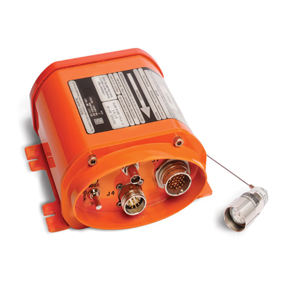
COMPONENT MAINTENANCE MANUAL 1152682 INTRODUCTION This publication provides maintenance instructions with illustrated parts breakdown for the RESCU 406AFN Emergency Locator Transmitter (ELT) Unit, P/N 1152682-2 manufactured by Honeywell International Inc., 3333 Unity Drive, Mississauga, Ontario, Canada (Federal Supply Code number 07217). -
Page 13: Description And Operation
COSPAS-SARSAT can match a unique 406 MHz identification code to a particular aircraft. A. Registration of the RESCU 406AFN by the airline operator must be completed at the following times: On delivery of new aircraft from the OEM, with a RESCU 406AFN installed. - Page 14 NOTE 2: Appendix D outlines the 406 MHz registration procedure. Description A. The RESCU 406AFN is an Automatic Fixed type ELT with NAV/GPS capability. The RESCU 406AFN is permanently fixed to the aircraft in a protected location and activates automatically upon impact.
- Page 15 1. BASIC FUNCTIONALITY REQUIRES ONLY TRANSMITTER UNIT, COAX AND ANTENNA 2. INTERCONNECT WIRING DEPENDS ON DESIRED FUNCTIONS TO AIRCRAFT WARNING SYSTEM 232402_2 System Block Diagram Figure 2 23-24-02 Page 3 Oct 27/06 © Honeywell International Inc. Do not copy without express permission of Honeywell.
- Page 16 B. The location of these components in the aircraft is shown in Figure 4. The basic system requirements for the RESCU 406AFN include the transmitter unit, antenna and the user supplied coax cable that connects the two components. This basic system can be upgraded at any time to...
- Page 17 COMPONENT MAINTENANCE MANUAL 1152682 CD PROGRAM (OPTIONAL) MESSAGE PROGRAMMER (OPTIONAL) TO AIM/NAIM MODULE OR TRANSMITTER UNIT 232402_3 Beacon Message Programmer (BMP) Figure 3 23-24-02 Page 5 Oct 27/06 © Honeywell International Inc. Do not copy without express permission of Honeywell.
- Page 18 COMPONENT MAINTENANCE MANUAL 1152682 AIM/NAIM 232402_4 RESCU 406AFN Component Locations Figure 4 23-24-02 Page 6 Oct 27/06 © Honeywell International Inc. Do not copy without express permission of Honeywell.
- Page 19 USER SUPPLIED INTERCONNECT WIRING USER SUPPLIED COAX CABLE ANTENNA MULTI-FUNCTION DISPLAY FLIGHT WARNING COMPUTER 232402_5-1 Sample System Configurations Figure 5 (Sheet 1 of 3) 23-24-02 Page 7 Oct 27/06 © Honeywell International Inc. Do not copy without express permission of Honeywell.
- Page 20 USER SUPPLIED COAX CABLE ANTENNA USER SUPPLIED INTERCONNECT WIRING REMOTE PANEL TO AIRCRAFT NAVIGATION SYSTEM 232402_5-2 Sample System Configurations Figure 5 (Sheet 2 of 3) 23-24-02 Page 8 Oct 27/06 © Honeywell International Inc. Do not copy without express permission of Honeywell.
- Page 21 AND WOULD NOT BE INCLUDED WITH THE SYSTEM IF THE SYSTEM ALREADY INCLUDES A REMOTE PANEL. 232402_5-3 Sample System Configurations Figure 5 (Sheet 3 of 3) 23-24-02 Page 9 Oct 27/06 © Honeywell International Inc. Do not copy without express permission of Honeywell.
- Page 22 Certification and Standards ......FAA (USA), COSPAS-SARSAT, TSO C-91a (FAA-USA), TSO C126 (FAA-USA), RTCA/DO-183, RTCA/DO-204, ED-62 (JAA) for battery P/N 1096801-1: TSO C-142 (FAA-USA), DO/RTCA-227 23-24-02 Page 10 Oct 27/06 © Honeywell International Inc. Do not copy without express permission of Honeywell.
- Page 23 ON, blinking, for transmit, with transmitter unit powering the remote panel. ON, short sequence of blink, for Built-in Test 23-24-02 Page 11 Oct 27/06 © Honeywell International Inc. Do not copy without express permission of Honeywell.
- Page 24 The transmitter unit requires removal and regular maintenance. The AIM or the NAIM, due to its simple circuitry and the RESCU 406AFN self-test, does not need removal or regular maintenance; aircraft specific programming data therefore remains uniquely with the designated aircraft.
- Page 25 Aircraft Operator Designator and Serial Number, User Location Protocol Transmits two analog signals at frequencies of 121.5 and 243 MHz for close-in homing. 23-24-02 Page 13 Oct 27/06 © Honeywell International Inc. Do not copy without express permission of Honeywell.
- Page 26 Program will NULL message, when AIM is connected to external 24-bit DIP switch module. Capable of interfacing to 24-bit DIP switch module. Does not need removal or regular maintenance. 23-24-02 Page 14 Oct 27/06 © Honeywell International Inc. Do not copy without express permission of Honeywell.
- Page 27 Figure 806. In addition to interfacing with the transmitter unit and various aircraft systems, it provides an alternate connection to a remote buzzer. 23-24-02 Page 15 Oct 27/06 © Honeywell International Inc. Do not copy without express permission of Honeywell.
- Page 28 121.5, 243 and 406 MHz. H. Antenna Features Transmitter to antenna connection via a single cable Blade-type antenna Triple frequency 121.5/243/406 MHz Vertical polarization 23-24-02 Page 16 Oct 27/06 © Honeywell International Inc. Do not copy without express permission of Honeywell.
- Page 29 A 121.5 and 243 MHz pulse will be transmitted to the antenna for approximately 0.5 second. A single 406 MHz pulse coded as a self-test signal will be transmitted approximately 3 seconds after activation. 23-24-02 Page 17 Oct 27/06 © Honeywell International Inc. Do not copy without express permission of Honeywell.
- Page 30 Self-Test Functionality (Refer to Figure 6) Self-test depending on configuration, validates the following: A. Transmitter Unit • Memory check • G-switch jumper installation 23-24-02 Page 18 Oct 27/06 © Honeywell International Inc. Do not copy without express permission of Honeywell.
- Page 31 1 Blink - Faulty NAIM 2 Blinks - Faulty DIP SWITCH SWITCH 3 Blinks - Faulty ARINC 232402_6 RESCU 406AFN Self-Test Validation and Fault Isolation Figure 6 23-24-02 Page 19 Oct 27/06 © Honeywell International Inc. Do not copy without express permission of Honeywell.
- Page 32 The RF Module generates three RF signals at 121.5, 243, and 406.028 MHz. The three RF signals are controlled by a microcontroller on the RF Module. 23-24-02 Page 20 Oct 27/06 © Honeywell International Inc. Do not copy without express permission of Honeywell.
- Page 33 The battery pack consists of five lithium-manganese-dioxide batteries connected in series to provide an approximate voltage of 13 to 14 V at the beginning of the battery lifetime. 23-24-02 Page 21/22 Oct 27/06 © Honeywell International Inc. Do not copy without express permission of Honeywell.
-
Page 34: Testing And Fault Isolation
ILLUSTRATED PARTS LIST (page 1001). C. Connector pin-outs for RESCU 406AFN are given in Tables 102 to 105. D. Fault isolation flowcharts for RESCU 406AFN are given in Figures 103 to 105. TABLE 101. TEST EQUIPMENT... - Page 35 Set the switch on the transmitter unit control panel to ARM. Set the switch on the remote control and transmitter unit control panel to ARMED and make sure that the LED is off. 23-24-02 Page 102 Oct 27/06 © Honeywell International Inc. Do not copy without express permission of Honeywell.
- Page 36 1 Blink - Faulty NAIM 2 Blinks - Faulty DIP SWITCH SWITCH 3 Blinks - Faulty ARINC 232402_101 RESCU 406AFN Self-Test Validation and Fault Isolation Figure 101 23-24-02 Page 103 Oct 27/06 © Honeywell International Inc. Do not copy without express permission of Honeywell.
- Page 37 121.5/243 MHz Power Output, Test # 1 Equipment Required HP 8590 spectrum analyzer (or equivalent) 30 dBm attenuator Unit under test (UUT) P/N 1152682-2 23-24-02 Page 104 Oct 27/06 © Honeywell International Inc. Do not copy without express permission of Honeywell.
- Page 38 Record the value for the 243 MHz output power, which shall be greater than +20.0 dBm. Place the switch on the transmitter unit back to the OFF position. 23-24-02 Page 105 Oct 27/06 © Honeywell International Inc. Do not copy without express permission of Honeywell.
- Page 39 30 dBm attenuator Test Procedure: Activate the transmitter unit by moving the switch on the transmitter unit from the OFF position to the TX position. 23-24-02 Page 106 Oct 27/06 © Honeywell International Inc. Do not copy without express permission of Honeywell.
- Page 40 If no such label is found, refer to Section 4 of RESCU 406 AF User Guide and Reference Manual 6C-520, to determine the correction factors. 23-24-02 Page 107 Oct 27/06 © Honeywell International Inc. Do not copy without express permission of Honeywell.
- Page 41 406 MHz carrier frequency, which shall be 406.028 MHz ±2 kHz. Place the switch on the transmitter unit back to the OFF position. Automatic Activation Test, Test # 6 Equipment Required None. 23-24-02 Page 108 Oct 27/06 © Honeywell International Inc. Do not copy without express permission of Honeywell.
- Page 42 24-bit aircraft address connected to the AIM, then the 15-HEX code message shall be according to the dip switch message, and the total message shall be the 112-bit format. 23-24-02 Page 109 Oct 27/06 © Honeywell International Inc. Do not copy without express permission of Honeywell.
- Page 43 (3 AMPS @ 10.5V) CURRENT VOLTAGE POWER 10.6 V dc (+/- 0.1V) TRANSMITTER UNIT 232402_102 Transmitter Unit Return to Service Test Setup Figure 102 23-24-02 Page 110 Oct 27/06 © Honeywell International Inc. Do not copy without express permission of Honeywell.
- Page 44 Connect the power supply to the power supply terminals on the transmitter unit. NOTE: Make sure the polarity is correct (red +ve and black –ve). 23-24-02 Page 111 Oct 27/06 © Honeywell International Inc. Do not copy without express permission of Honeywell.
- Page 45 NOTE). NOTE 1: The 15-HEX code presumes that the transmitter unit was pre-loaded with the default longitude/latitude co-ordinates before removal from the aircraft. 23-24-02 Page 112 Oct 27/06 © Honeywell International Inc. Do not copy without express permission of Honeywell.
- Page 46 J1-14 and pin J1-16. To select North American G- switch (FAA G-switch), insert a shorting link between pin J1-15 and pin J1-16 (refer to Table 102). 23-24-02 Page 113 Oct 27/06 © Honeywell International Inc. Do not copy without express permission of Honeywell.
- Page 47 FAA regulations. G SW SENSE Output Has function as contact closure for Required JAA G SWITCH or FAA G SWITCH. 23-24-02 Page 114 Oct 27/06 © Honeywell International Inc. Do not copy without express permission of Honeywell.
- Page 48 A/C Address Bit 7 Input Bit 7 info from Aircraft Address Bank Optional (used with (closure to ground/open circuit) 24-bit DIP switch module) 23-24-02 Page 115 Oct 27/06 © Honeywell International Inc. Do not copy without express permission of Honeywell.
- Page 49 A/C Address Bit 21 Input Bit 21 info from Aircraft Address Bank Optional (used with (closure to ground/open circuit) 24-bit DIP switch module) 23-24-02 Page 116 Oct 27/06 © Honeywell International Inc. Do not copy without express permission of Honeywell.
- Page 50 VEXT Input BMP programming only. Not used when installed in aircraft DC Ground Connection 28 VDC Input +28 V dc Power 23-24-02 Page 117 Oct 27/06 © Honeywell International Inc. Do not copy without express permission of Honeywell.
- Page 51 Allows programming of 24-bit Aircraft Optional (if NAIM Address by external switch panel. Open and the 24-bit DIP circuit interpreted as zero. switch module are both installed) 23-24-02 Page 118 Oct 27/06 © Honeywell International Inc. Do not copy without express permission of Honeywell.
- Page 52 Allows programming of 24-bit Aircraft Optional (if AIM Address by external switch panel. Open and the 24-bit DIP circuit interpreted as zero. switch module are both installed) 23-24-02 Page 119 Oct 27/06 © Honeywell International Inc. Do not copy without express permission of Honeywell.
- Page 53 Required position of the 3-position functional switch. EXTERNAL ON Output To transmitter unit, to send the Required position of the 3-position functional switch. 23-24-02 Page 120 Oct 27/06 © Honeywell International Inc. Do not copy without express permission of Honeywell.
- Page 54 Installed System Tests. If the results of one of those tests are unsatisfactory, use the Fault Isolation Flowcharts (Figures 103 to 105) to isolate the system component that is the problem. 23-24-02 Page 121 Oct 27/06 © Honeywell International Inc. Do not copy without express permission of Honeywell.
- Page 55 Configuration No. 2 – Transmitter Unit, Remote Panel and AIM or NAIM • Configuration No. 3 – Transmitter Unit, Remote Panel, AIM or NAIM and 24-bit DIP switch module 23-24-02 Page 122 Oct 27/06 © Honeywell International Inc. Do not copy without express permission of Honeywell.
- Page 56 TEST #2 FAIL? 2) REPLACE REMOTE PANEL. 3) REPLACE TRANSMITTER UNIT. NO FAILURES, SYSTEM FUNCTIONAL 232402_103 Fault Isolation Flowchart – Configuration No. 1 Figure 103 23-24-02 Page 123 Oct 27/06 © Honeywell International Inc. Do not copy without express permission of Honeywell.
- Page 57 TEST #2 FAIL? 2) REPLACE REMOTE PANEL. 3) REPLACE TRANSMITTER UNIT. NO FAILURES, SYSTEM FUNCTIONAL 232402_104 Fault Isolation Flowchart – Configuration No. 2 Figure 104 23-24-02 Page 124 Oct 27/06 © Honeywell International Inc. Do not copy without express permission of Honeywell.
- Page 58 TEST #2 FAIL? 2) REPLACE REMOTE PANEL. 3) REPLACE TRANSMITTER UNIT. NO FAILURES, SYSTEM FUNCTIONAL 232402_105 Fault Isolation Flowchart – Configuration No. 3 Figure 105 23-24-02 Page 125/126 Oct 27/06 © Honeywell International Inc. Do not copy without express permission of Honeywell.
-
Page 59: Disassembly
1152682 DISASSEMBLY General The components of the RESCU 406AFN Emergency Locator Transmitter are repaired by replacement. Therefore the only disassembly required is removal of individual components for replacement or testing. Refer to Appendix A for more information on installation. 23-24-02... -
Page 60: Cleaning
AVOID SKIN CONTACT. DO NOT IMMERSE ELECTRONIC PARTS IN SOLVENT. The external surfaces of the components of the RESCU 406AFN Emergency Locator Transmitter may be cleaned with a non-conductive stiff bristle brush or a clean cloth. If use of a solvent is necessary, apply with a gentle manual agitation and wipe with a lint-free cloth. -
Page 61: Check
Visually inspect the switch and LED on the front panel of the unit. 23-24-02 Page 501 Oct 27/06 © Honeywell International Inc. Do not copy without express permission of Honeywell. - Page 62 Ensure that all cabling has sufficient slack that the cable or connectors are never under stress that could be amplified under turbulent or vibrational conditions during flight. 23-24-02 Page 502 Oct 27/06 © Honeywell International Inc. Do not copy without express permission of Honeywell.
- Page 63 Make sure that each connector is firmly secured to its mating connector. 23-24-02 Page 503/504 Oct 27/06 © Honeywell International Inc. Do not copy without express permission of Honeywell.
-
Page 64: Repair
1152682 REPAIR General Repair of the RESCU 406AFN Emergency Locator Transmitter is limited to the replacement of any LRU found to be faulty in accordance with the Fault Isolation Flowcharts (refer to Figures 103 to 105) and/or battery replacement. A. LRU Replacement Replace any faulty LRU by referring to the instructions in Appendix A. - Page 65 TRANSMITTER CONNECTORS UNIT PULL TABS BATTERY PACK TRANSMITTER UNIT CONNECTOR BATTERY PACK CONNECTOR BATTERY PACK COVER TRANSMITTER UNIT 232402_601 Battery Replacement Figure 601 23-24-02 Page 602 Oct 27/06 © Honeywell International Inc. Do not copy without express permission of Honeywell.
- Page 66 1152682 Shipping of Battery The battery pack used in the RESCU 406AFN is safe for transport in bulk by itself as well as installed in the Transmitter Unit on passenger aircraft in accordance with exemption 173.185 (part c) of the Federal Department of Transportation Title 49 Code of Regulations (CFR).
-
Page 67: Assembly (Including Storage)
A. Store the components of the RESCU 406AFN Emergency Locator Transmitter in heatseal bags with desiccant packs (refer to Table 701). B. The components of the RESCU 406AFN Emergency Locator Transmitter may be stored for an indefinite period within a temperature range of –55 to +85°C (–67.0° to 185°F). -
Page 68: Fits And Clearances
COMPONENT MAINTENANCE MANUAL 1152682 FITS AND CLEARANCES Overall Dimensions The overall dimensions of the components of the RESCU 406AFN Emergency Locator Transmitter are shown in Figures 801 through 808. 23-24-02 Page 801 Oct 27/06 © Honeywell International Inc. Do not copy without express permission of Honeywell. - Page 69 139.00 [5.472] MAX CONNECTOR: MS83723/74R1624N MATES WITH: MS24266R16B24SN MS83723/75R1624N 87.00 [3.425] MAX NOTE: DIMENSIONS ARE IN MILLIMETERS [INCHES] 232402_801 Transmitter Unit Figure 801 23-24-02 Page 802 Oct 27/06 © Honeywell International Inc. Do not copy without express permission of Honeywell.
- Page 70 150.30 ± 0.250 [5.917 ± 0.010] 166.00 [6.535] MAX 139.00 [5.472] MAX 87.00 [3.425] MAX NOTE: DIMENSIONS ARE IN MILLIMETERS [INCHES] 232402_802 Aircraft Identification Module (AIM) Figure 802 23-24-02 Page 803 Oct 27/06 © Honeywell International Inc. Do not copy without express permission of Honeywell.
- Page 71 166.00 [6.535] MAX 139.00 [5.472] MAX 87.00 [3.425] MAX NOTE: DIMENSIONS ARE IN MILLIMETERS [INCHES] 232402_803 NAV Aircraft Identification Module (NAIM) Figure 803 23-24-02 Page 804 Oct 27/06 © Honeywell International Inc. Do not copy without express permission of Honeywell.
- Page 72 COMPONENT MAINTENANCE MANUAL 1152682 17.00 [0.669] MAX. 52.62 [2.071] C/C 280.00 [10.974] MAX. 160.02 [6.300] C/C 232402_804 Transmitter Unit with AIM Figure 804 23-24-02 Page 805 Oct 27/06 © Honeywell International Inc. Do not copy without express permission of Honeywell.
- Page 73 COMPONENT MAINTENANCE MANUAL 1152682 22.00 [0.87] MAX. 52.62 [2.071] C/C 280.00 [10.974] MAX. 160.02 [6.300] C/C 232402_805 Transmitter Unit with NAIM Figure 805 23-24-02 Page 806 Oct 27/06 © Honeywell International Inc. Do not copy without express permission of Honeywell.
- Page 74 SERIES 1 67.00 [2.638] MAX. 146.05 [5.750] MAX. 14.21 [0.559] 136.27 [5.365] 38.10 [1.500] MAX. ARMED TEST/RESET 14.21 [0.559] 232402_806 Remote Panel Figure 806 23-24-02 Page 807 Oct 27/06 © Honeywell International Inc. Do not copy without express permission of Honeywell.
- Page 75 38.1 [1.50] 71.3 [2.81] 28.6 [1.13] 31.8 [1.25] NOTE: DIMENSIONS ARE IN MILLIMETERS [INCHES] 232402_807 Antenna (Chelton P/N 2614-82 and 2624-82) Figure 807 23-24-02 Page 808 Oct 27/06 © Honeywell International Inc. Do not copy without express permission of Honeywell.
- Page 76 5.6 F100° (0.22 x 100° CSK.) FOR NO. 10 100° MOUNTING HARDWARE NOTE: DIMENSIONS ARE IN MILLIMETERS [INCHES] 232402_808 Antenna (Sensor Systems P/N S65-8282-406) Figure 808 23-24-02 Page 809/810 Oct 27/06 © Honeywell International Inc. Do not copy without express permission of Honeywell.
-
Page 77: Special Tools, Fixtures And Equipment
Rescu 406 Testing/Troubleshooting Coaxial from TU to BT100AVS 50 ohm coaxial (V07217) Programming Cable 12/28 V dc Power Supply Cables Generic (V07217) Programming 23-24-02 Page 901/902 Oct 27/06 © Honeywell International Inc. Do not copy without express permission of Honeywell. -
Page 78: Illustrated Parts List
(e.g., AN, MS, NAS, Military Standard, etc.), nor with respect to Honeywell part numbers. C. The Honeywell part numbering system and LRU identification system are shown in Table 1. D. For the purposes of spares procurement, any item may be ordered from its applicable true manufacturer (or authorized supplier), or from Honeywell. - Page 79 This is the complete Part Number. This is the complete CS 1234 Part Number. This is the complete Part Number. Manufacturer's Part Numbering System Table 1 23-24-02 Page 1002 Oct 27/06 © Honeywell International Inc. Do not copy without express permission of Honeywell.
- Page 80 Replaces REPLS The part in the part number column replaces and is interchangeable with the item number. 23-24-02 Page 1003 Oct 27/06 © Honeywell International Inc. Do not copy without express permission of Honeywell.
- Page 81 B. When the entire page is changed for whatever purpose, a revision bar will appear opposite the page number and the date of issue will change. 23-24-02 Page 1004 Oct 27/06 © Honeywell International Inc. Do not copy without express permission of Honeywell.
- Page 82 CHELTON ANTENNAS, DOURDAN, F-91410, FRANCE 07217 HONEYWELL INTERNATIONAL INC., 3333 UNITY DRIVE, MISSISSAUGA, ONTARIO L5L 3S6, CANADA 13691 SENSOR SYSTEMS INC., CHATSWORTH, CA 91311, USA 23-24-02 Page 1005 Oct 27/06 © Honeywell International Inc. Do not copy without express permission of Honeywell.
- Page 83 R 1153006-1 –10B –60A R 1153008-1 –10C –60B R 1153236-1 –10D –60C R 1153396-1 –20A –70A R 2614-82 –40A R 2624-82 –40B –90A 23-24-02 Page 1006 Oct 27/06 © Honeywell International Inc. Do not copy without express permission of Honeywell.
- Page 84 COMPONENT MAINTENANCE MANUAL 1152682 THIS PAGE INTENTIONALLY LEFT BLANK 23-24-02 Page 1007 Oct 27/06 © Honeywell International Inc. Do not copy without express permission of Honeywell.
- Page 85 COMPONENT MAINTENANCE MANUAL 1152682 232402_IPL1 RESCU 406AFN Emergency Locator Transmitter (ELT) P/N 1152682 Figure 1 23-24-02 Page 1008 Oct 27/06 © Honeywell International Inc. Do not copy without express permission of Honeywell.
- Page 86 . ANTENNA, 121.5 MHz, 243 MHz .... AND 406 MHz (V13691) (SCD 111-902-9003) –50 MS51957-28 . DELETED –50A 1096801-1 . BATTERY PACK ........– Items not illustrated 23-24-02 Page 1009 Oct 27/06 © Honeywell International Inc. Do not copy without express permission of Honeywell.
- Page 87 –90A 2624-82 . DELETED –90B S65-8282-406 . DELETED –90C MS51957-28 . . SCREW ..........---***--- –100 1096801-1 . DELETED – Items not illustrated 23-24-02 Page 1010 Oct 27/06 © Honeywell International Inc. Do not copy without express permission of Honeywell.
- Page 88 A. This appendix provides general installation guidelines for each component of the system. B. The RESCU 406AFN Emergency Locator Transmitter system consists, at a minimum, of a transmitter unit and an antenna. A full system with all the options consists of a transmitter unit, a remote panel, an AIM or a NAIM, a 24-bit DIP switch module and an antenna as well as any associated wiring between components.
- Page 89 COMPONENT MAINTENANCE MANUAL 1152682 G. If the ELT system does not include an AIM or a NAIM, register the RESCU 406AFN Hex Identification Code (recorded on the Hex identification label on the transmitter unit) with the appropriate National COSPAS/SARSAT office according to the instructions in Appendix D of this manual.
- Page 90 COMPONENT MAINTENANCE MANUAL 1152682 232402_A1 AIM Wiring to Optional 24-Bit DIP Switch Module Figure A-1 23-24-02 Page A-3 Oct 27/06 © Honeywell International Inc. Do not copy without express permission of Honeywell.
- Page 91 B. Make sure that there is enough space behind the cockpit panel for the connector and associated wiring at the back of the remote panel. 23-24-02 Page A-4 Oct 27/06 © Honeywell International Inc. Do not copy without express permission of Honeywell.
- Page 92 COMPONENT MAINTENANCE MANUAL 1152682 232402_A2 NAIM Wiring to Optional 24-Bit DIP Switch Module Figure A-2 23-24-02 Page A-5 Oct 27/06 © Honeywell International Inc. Do not copy without express permission of Honeywell.
- Page 93 AIM or NAIM) with the Hex code generated by the 24-bit DIP switch module and affix it to the transmitter unit. C. Register the RESCU 406AFN Hex identification code (recorded on the Hex identification label on the transmitter unit) with the appropriate National COSPAS/SARSAT office according to the instructions in Appendix D of this manual.
- Page 94 24-bit DIP switch module is used to input the COSPAS-SARSAT 24-bit data for the Aircraft Address Number protocol and requires no power source to operate. 23-24-02 Page A-7/A-8 Oct 27/06 © Honeywell International Inc. Do not copy without express permission of Honeywell.
- Page 95 NOTE: The materials in this section may only represent a hazard if the integrity of the battery is compromised or if the battery is physically or electrically abused. 23-24-02 Page B-1 Oct 27/06 © Honeywell International Inc. Do not copy without express permission of Honeywell.
- Page 96 Personal protective equipment for damaged batteries should include chemical-resistant gloves and safety glasses. In the event of a fire, SCBA should be worn along with thermally protective outer garments. 23-24-02 Page B-2 Oct 27/06 © Honeywell International Inc. Do not copy without express permission of Honeywell.
- Page 97 23-24-02 Page B-3/B-4 Oct 27/06 © Honeywell International Inc. Do not copy without express permission of Honeywell.
- Page 98 Safety Kleen BDT 4255 Research Parkway Clarence, NY 14031 Phone: (716) 759-2868 Types: Lithium, alkaline, nickel-cadmium, mercury, lead-acid Fax: (716) 759-6034 Contact: Joel Guptill 23-24-02 Page C-1 Oct 27/06 © Honeywell International Inc. Do not copy without express permission of Honeywell.
- Page 99 For more information, contact OPP at: Office of Pollution Prevention Ohio Environmental Protection Agency P.O. Box 1049 Columbus, Ohio 43216-1049 Phone (614) 644-3469 Fax: (614) 728-1245 E-mail: [email protected] 23-24-02 Page C-2 Oct 27/06 © Honeywell International Inc. Do not copy without express permission of Honeywell.
- Page 100 For other national registration forms, please contact the appropriate national COSPAS-SARSAT registry offices. C. The RESCU 406AFN shall be registered with the national registry office in the country coded into the “country code” field of the 406 MHz digital message. The country of registration shall also be indicated on the Transmitter Unit identification label.
- Page 101 COMPONENT MAINTENANCE MANUAL 1152682 232402_D1-1 USA 406 MHz Registration Form, for the National Oceanographic and Atmospheric Administration (NOAA) Figure D-1 (Sheet 1 of 2) 23-24-02 Page D-2 Oct 27/06 © Honeywell International Inc. Do not copy without express permission of Honeywell.
- Page 102 COMPONENT MAINTENANCE MANUAL 1152682 232402_D1-2 USA 406 MHz Registration Form, for the National Oceanographic and Atmospheric Administration (NOAA) Figure D-1 (Sheet 2 of 2) 23-24-02 Page D-3 Oct 27/06 © Honeywell International Inc. Do not copy without express permission of Honeywell.
- Page 103 COMPONENT MAINTENANCE MANUAL 1152682 232402_D2-1 Registration Form for 406 MHz, Germany Figure D-2 (Sheet 1 of 2) 23-24-02 Page D-4 Oct 27/06 © Honeywell International Inc. Do not copy without express permission of Honeywell.
- Page 104 COMPONENT MAINTENANCE MANUAL 1152682 232402_D2-2 Registration Form for 406 MHz, Germany Figure D-2 (Sheet 2 of 2) 23-24-02 Page D-5/D-6 Oct 27/06 © Honeywell International Inc. Do not copy without express permission of Honeywell.