Table of Contents
Quick Links
IMPORTANT SERVICE NOTES (FOR U.S.A. ONLY) ....................................................................................................... 2
SPECIFICATIONS ............................................................................................................................................................. 3
NAMES OF PARTS ........................................................................................................................................................... 4
DISASSEMBLY .................................................................................................................................................................. 6
ADJUSTMENT ................................................................................................................................................................... 9
DESCRIPTION OF CIRCUIT FOR 1-BIT UNIT ................................................................................................................. 9
TO CHECK AND CANCEL PROTECT CIRCUIT DETECTION LINE .............................................................................. 10
NOTES ON SCHEMATIC DIAGRAM .............................................................................................................................. 11
TYPES OF TRANSISTOR AND LED ............................................................................................................................... 11
BLOCK DIAGRAM ........................................................................................................................................................... 12
WIRING SIDE OF P.W.BOARD / SCHEMATIC DIAGRAM ............................................................................................. 22
VOLTAGE ........................................................................................................................................................................ 41
WAVEFORMS OF 1-BIT CIRCUIT .................................................................................................................................. 42
FUNCTION TABLE OF IC ................................................................................................................................................ 43
REPLACEMENT PARTS LIST/EXPLODED VIEW
All manuals and user guides at all-guides.com
SERVICE MANUAL
CONTENTS
SHARP CORPORATION
1-BIT DIGITAL HOME THEATER
SD-AT1000
MODEL
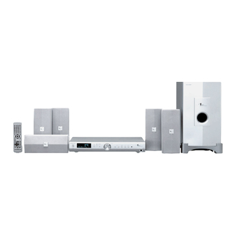
SD-AT1000 1-Bit Digital Home Theater consisting of
SD-AT1000 (main unit), CP-AT1000F (front speakers),
CP-AT1000C (center speaker), CP-AT1000R (surround
speakers) and CP-AT1000SW (subwoofer).
• In the interests of user-safety the set should be restored to its
original condition and only parts identical to those specified be
used.
This document has been published to be used
for after sales service only.
The contents are subject to change without notice.
SD-AT1000
No. S4336SDAT1000
Page
Table of Contents

Related Manuals for Sharp SD-AT1000


Summary of Contents for Sharp SD-AT1000
-
Page 1: Table Of Contents
No. S4336SDAT1000 1-BIT DIGITAL HOME THEATER SD-AT1000 MODEL SD-AT1000 1-Bit Digital Home Theater consisting of SD-AT1000 (main unit), CP-AT1000F (front speakers), CP-AT1000C (center speaker), CP-AT1000R (surround speakers) and CP-AT1000SW (subwoofer). • In the interests of user-safety the set should be restored to its original condition and only parts identical to those specified be used. -
Page 2: Important Service Notes (For U.s.a. Only)
Caution: The supplied speakers are exclusively for SD-AT1000. Do not connect them to other equipment, and do not connect other speakers to SD-AT1000. It may cause malfunction. Do not mistake the and , and right and left terminals of the speaker cords. (The right speaker is placed on the right when you face the unit.) -
Page 3: Specifications
All manuals and user guides at all-guides.com SD-AT1000 FOR A COMPLETE DESCRIPTION OF THE OPERATION OF THIS UNIT, PLEASE REFER TO THE OPERATION MANUAL. SPECIFICATIONS SD-AT1000 (For U.S.A.) SD-AT1000 (For Canada) Main unit Main unit Power source AC 120 V, 60 Hz... -
Page 4: Names Of Parts
All manuals and user guides at all-guides.com SD-AT1000 NAMES OF PARTS SD-AT1000 Main unit (front panel) (3) (4) (6) (7) (9) (10)(11) (12) (13) 10 11 1. Sleep Indicator 6. Power Button 2. FM Stereo Receiving Indicator 7. Timer Set Indicator 3. - Page 5 All manuals and user guides at all-guides.com SD-AT1000 SD-AT1000 Remote control 1. Remote Control Transmitter 2. TV Operation Buttons 3. VCR Operation Buttons 4. Input Select Buttons 5. Clear Button 6. Cursor Buttons 7. Amplifier Return Button 8. Amplifier Initial Setting Button 9.
-
Page 6: Disassembly
All manuals and user guides at all-guides.com SD-AT1000 DISASSEMBLY SD-AT1000 Caution on Disassembly Follow the below-mentioned notes when disassembling the unit and reassembling it, to keep it safe and ensure (A1)x1 ø3x10mm excellent performance: Front 1. Be sure to remove the power supply plug from the wall Panel outlet before starting to disassemble the unit. - Page 7 All manuals and user guides at all-guides.com SD-AT1000 CP-AT1000F/CP-AT1000C (E1)x1 (E3)x1 STEP REMOVAL PROCEDURE FIGURE ø3x8mm Front Panel 1. Screw ...... (A1) x6 (D1)x2 Headphones ø3x8mm Speaker 1. Screw ...... (B1) x4 (E2)x1 (D1)x3 Speaker Box ø3x8mm (D1)x1 ø3x8mm (A1)x6 ø3x12mm...
- Page 8 All manuals and user guides at all-guides.com SD-AT1000 CP-AT1000R CP-AT1000SW STEP REMOVAL PROCEDURE FIGURE REMOVAL PROCEDURE FIGURE STEP Front Panel 1. Screw ...... (A1) x6 Woofer 1. Screw ....(A1) x10 2. Subwoofer Stand ..(A2) x1 Speaker 1. Screw ...... (B1) x2 (A1)x10 ø4x20mm...
-
Page 9: Adjustment
All manuals and user guides at all-guides.com SD-AT1000 ADJUSTMENT POWER PWB 1-bit amplifier's output offset voltage adjustment Adjust VRA100, VRA101, VRA200, VRA201, VRA300 and VRA301 so that the DC voltage between speaker terminals + and - is set to 0 ± 5 mV at AC 120 V. -
Page 10: To Check And Cancel Protect Circuit Detection Line
All manuals and user guides at all-guides.com SD-AT1000 TO CHECK AND CANCEL PROTECT CIRCUIT DETECTION LINE 1 1 1 1 1 1: In this model the microcomputer (IC701) detects the following Abnormal drop in the output voltage of each regulator... -
Page 11: Notes On Schematic Diagram
All manuals and user guides at all-guides.com SD-AT1000 NOTES ON SCHEMATIC DIAGRAM • Resistor: • Schematic diagram and Wiring Side of P.W.Board for this model are subject to change for improvement without prior To differentiate the units of resistors, such symbol as K and M are used: the symbol K means 1000 ohm and the symbol notice. -
Page 12: Block Diagram
All manuals and user guides at all-guides.com SD-AT1000 JT501 JT502 LINE2/LINE3 LINE1 INPUT/ OUTPUT TERMINAL INPUT TERMINAL R-CH R_CH A_GND A_GND L_CH L-CH D_GND D_GND H.P SW H.P SW Q533 Q531 Q532 MON_OUTL 5 6 7 8 IC520 – TJM4558CD... - Page 13 All manuals and user guides at all-guides.com SD-AT1000 FRONT_LCH FRONT L-CH Q513 IC411 – TJM4558CD + VSS L_MUTE OPE AMP. – Q512 Q515 F_S_MUTE Q533 FRONT R-CH FRONT_RCH OUTSR_LCH SURROND L-CH Q531 IC412 Q524 – Q532 TJM4558CD OPE AMP. –...
- Page 14 All manuals and user guides at all-guides.com SD-AT1000 IC110 SI3050LUS VOLTAGE REGULATOR PROTECT DSP_CS DSP_SCCLK DSP_SCDIN DSP_SCDOUT DSP_RESET DSP_INTREQ COD_DO COD_DI +5V(A) COD_CLK COD_CSN DIG_FUNC+B NONPCM 22 21 20 19 18 17 16 15 14 13 12 D_+5V VREFH SDTI1...
- Page 15 All manuals and user guides at all-guides.com SD-AT1000 ZD101 28 27 26 25 24 23 22 21 20 19 18 14 13 12 11 SCLKN2 LRCLKN2 EMAD0 CLKIN EMAD1 EMAD2 EMAD3 IC101 DGND2 CS493264 +2.5V(A) AGND EMAD4 RESET EMAD5 +3.3V(D)
- Page 16 All manuals and user guides at all-guides.com SD-AT1000 FL701 FL DISPLAY 9 10 11 12 80 79 78 77 76 75 74 73 72 71 70 DIG8 DIG7 DIG6 DIG5 DIG4 –VP FOR FL DIG3 AC_RELAY DIG2 DIG1 SP_RELAY IC701...
- Page 17 All manuals and user guides at all-guides.com SD-AT1000 NON_PCM VOL_CL DIG_FUNC_+B VOL_DA COD_CSN COD_CSN COD_CLK COD_CLK COD_DI COD_DI COD_DO COD_DO STEREO_LED SURR_LED DTS_LED STD_LED DSP_INTERQ DSP_INTREQ DSP_RESET DSP_RESET DSP_SCDOUT DSP_SCDOUT DSP_SCDIN DSP_SCDIN DSP_SCCLK DSP_CS DSP_CS DSP_SCCLK DIMMER SYS_STOP Q710 REMOTE SENSOR...
- Page 18 All manuals and user guides at all-guides.com SD-AT1000 TO MAI TO 1-BIT AMP. SECTION CNA104 TO 1-BIT AMP. SECTION CNS701 CNS933 FROM DISPLAY SECTION CNP901 BI933 D957 Q932 IC934 KIA7805AP VOLTAGE REGULATOR Q931 Q895 IC931 SE-B2 IC933 ERROR KIA7809AP AMP.
- Page 19 All manuals and user guides at all-guides.com SD-AT1000 CNP531 TO 1-BIT AMP. SECTION TO MAIN SECTION SUBWOOFER CNS931 CENTER SURROND FRONT 18 19 22 23 26 27 BI931 D947 Q892 SP__RLY SP__RLY D954 IC937 AN77L05 VOLTAGE REGULATOR ZD937 Q950 PC901...
- Page 20 All manuals and user guides at all-guides.com SD-AT1000 CNS933 FROM POWER SECTION CNA104 ANALOG IN R-CH ANALOG IN L-CH ANALOG LFA403 LFA402 A+5V 14 15 16 17 21 22 23 24 DA404 QA415 CXA100 ICA401 11.2896 MHz TJM4558CD QA414 OPE AMP.
- Page 21 All manuals and user guides at all-guides.com SD-AT1000 CNS500 FROM MAIN SECTION 10 11 12 CNA100 ANALOG IN L-CH ANALOG IN R-CH ANALOG IN R-CH 21 22 23 24 21 22 23 24 AMP_VCC AMP_VCC VBOOTB VBOOTB VBOOTB VBOOTB VBOOTA...
-
Page 22: Wiring Side Of P.w.board / Schematic Diagram
All manuals and user guides at all-guides.com SD-AT1000 HEADPHONES PWB-A3 MAIN PWB-A1 P24 4 - F TO DISPLAY PWB (BOTTOM VIEW) (BOTTOM VIEW) CNP701 LUG3 CNP601 ZD402 ZD403 CNS601 R577 R575 Q514 Q545 R572 R574 R578 CNP501 R571 R615 Q544... - Page 23 All manuals and user guides at all-guides.com SD-AT1000 MAIN PWB-A1 HEADPHONES PWB-A3 (TOP VIEW) (TOP VIEW) Q504 R593 R585 R594 C637 R583 Q518 C641 Q598 C587 R604 C588 Q541 R605 R606 Q516 COLOR TABLE C642 Q543 R653 C638 Q527 BROWN...
- Page 24 All manuals and user guides at all-guides.com SD-AT1000 LED703 Q701 JOG701 RM717 Q704 JOG VOLUME C717 C711 Q709 Q710 C725 RM723 SW702 SW704 C727 LINE R753 TUNING UP R793 LED70 SW705 D703 TUNING RM702 DOWN Q702 IC703 R752 SW701 SW703...
- Page 25 All manuals and user guides at all-guides.com SD-AT1000 DISPLAY PWB-A2 (TOP VIEW) R764 R759 R760 R756 L701 R791 R722 C702 R713 R712 R711 DISPLAY PWB-A2 (BOTTOM VIEW) R724 R709 R798 R727 R723 R708 R726 RM719 C715 R725 RM721 C703 C714...
- Page 26 All manuals and user guides at all-guides.com SD-AT1000 POWER PWB-B (TOP VIEW) • The numbers are waveform numbers shown in page 42. Figure 26 WIRING SIDE OF P.W.BOARD (5/8) – 26 –...
- Page 27 All manuals and user guides at all-guides.com SD-AT1000 DA315 DA406 CA345 DA311 RA356 DA314 RA358 D889 R861 R862 D890 DA332 10 15 CA392 RA361 DA330 ICA300 CA346 DA308 DA310 R858 R899 D887 DA215 R857 DA400 DA402 DA213 DA405 CA259 DA233...
- Page 28 All manuals and user guides at all-guides.com SD-AT1000 POWER PWB-B (BOTTOM VIEW) CA387 LFA301 LA303 RA331 CA353 RA349 CA355 RA335 CA351 CA379 RA351 CA349 RL898 RA337 CA383 RA327 RA343 RA347 RA353 RA416 RA341 LA301 RA375 QA400 RA339 RA412 ICA301 RA409...
- Page 29 All manuals and user guides at all-guides.com SD-AT1000 AC POWER SUPPLY CORD AC 120 V, 60 Hz SO889 SPEAKER CNS902 TERMINAL CNP902 C873 VA901 R901 C901 C911 R903 C904 C903 TH901 C916 C912 D901 C922 R917 1 2 3 C921...
- Page 30 All manuals and user guides at all-guides.com SD-AT1000 JT502 JT501 LINE1 INPUT/ LINE2/LINE3 OUTPUT TERMINAL INPUT TERMINAL C171 0.0022 R-CH R_CH A_GND A_GND L-CH L_CH D_GND D_GND 100P(CH) H.P SW H.P SW 2.2 µH 100P R536 R535 R639 R635 R632...
- Page 31 All manuals and user guides at all-guides.com SD-AT1000 MAIN PWB-A1 (1/2) LINE2 SIGNAL FM SIGNAL LINE3 SIGNAL LINE1 SIGNAL C413 R417 C417 R411 R421 R543 2.2K 10/16 10/16 3.9K 8.2K FRONT_LCH FRONT L-CH ZD557 C415 ZD558 R423 DZ6.2BSC DZ6.2BSC C419 3.3K...
- Page 32 All manuals and user guides at all-guides.com SD-AT1000 FM SIGNAL C117 C144 D103 DS1SS133 C148 10/16 R141 FFC702 PROTECT DSP_CS DSP_SCCLK DSP_SCDIN DSP_SCDOUT C196 GND(D) C165 R196 100P(CH) 0.001 DSP_RESET C195 3.3K DSP_INTREQ R195 100P(CH) C194 3.3K R194 100P(CH) C166 3.3/16...
- Page 33 All manuals and user guides at all-guides.com SD-AT1000 C118 C137 C138 C154 C151 C152 10/16 10/16 GND(D) C163 14 13 12 11 10 28 27 26 25 24 23 22 21 20 19 18 100/10 SCLKN2 +2.5V(A) R113 LRCLKN2 R119...
- Page 34 All manuals and user guides at all-guides.com SD-AT1000 FL701 FL DISPLAY 9 10 11 12 C701 1/50 80 79 78 77 76 75 74 73 72 71 70 DIG8 DIG7 DIG6 DIG5 DIG4 –VP FOR FL DIG3 AC_RELAY DIG2 DIG1...
- Page 35 All manuals and user guides at all-guides.com SD-AT1000 DISPLAY PWB-A2 R767 C718 1/50 R756 FFC702 R755 4.7K NON_PCM R768 VOL_CL DIG_FUNC_+B R769 VOL_DA R754 COD_CSN 4.7K R770 COD_CSN COD_CLK R771 COD_CLK COD_DI R772 COD_DI COD_DO R773 COD_DO R751 R774 STEREO_LED...
- Page 36 All manuals and user guides at all-guides.com SD-AT1000 P38 2 - A P38 1 - H TO 1-BIT AMP. SECTION TO 1-BIT AMP. SECTION CNA104 P34 1 - C FROM DISPLAY PWB CNS933 CNS701 BI933 CNP901 Q932 C958 KTC3199 GR 0.047...
- Page 37 All manuals and user guides at all-guides.com SD-AT1000 P31 12 - E TO MAIN PWB P38 3~6 - H, P39 7~11 - H CNP531 TO 1-BIT AMP. SECTION SUBWOOFER CNS931 CENTER SURROUND FRONT 18 19 22 23 26 27 BI931...
- Page 38 All manuals and user guides at all-guides.com SD-AT1000 P36 2 - A FROM POWER SECTION CNS933 P40 1 - C TO PROTECT CIRCUIT PWB CNS02 CNA104 BI105 ANALOG IN R-CH ANALOG IN L-CH ANALOG IN R- LFA403 LFA402 CA409 CA411...
- Page 39 All manuals and user guides at all-guides.com SD-AT1000 P31 12 - C FROM MAIN PWB CNS500 10 11 12 CNA100 POWER PWB-B (2/2) ANALOG IN R-CH ANALOG IN L-CH ANALOG IN R-CH FM SIGNAL CA332 47/10 RA205 RA305 RA204 CA200...
- Page 40 All manuals and user guides at all-guides.com SD-AT1000 PROTECT CIRCUIT PWB-C CNS02 RS07 OFFSET COM 4.7K RS06 QS07 4.7K RS04 QS08 KTC3199 GR KTC3199 GR CNS01 OFFSET COM RS05 QS06 4.7K KTC3199 GR SW_+5V DS03 OFFSET DS1SS133 PROTECT CS03 DS01...
-
Page 41: Voltage
All manuals and user guides at all-guides.com SD-AT1000 VOLTAGE IC701 IC501 IC101 IC102 ICA100 ICA202 VOLTAGE VOLTAGE VOLTAGE VOLTAGE VOLTAGE VOLTAGE VOLTAGE VOLTAGE VOLTAGE 2.81 V 51 0 V 41 0 V 2.51 V 2.44 V 5.00 V 13 0 V 3.49 V... -
Page 42: Waveforms Of 1-Bit Circuit
All manuals and user guides at all-guides.com SD-AT1000 WAVEFORMS OF 1-BIT CIRCUIT 2.00 V/div 2.00 V/div 2.00V/div 2.00V/div AD IC Output + Side LEVEL SHIFT OUT DEAD TIME - Side 194.545465 µs 500 ns/div 520 mV 50.0 ns/div 0.0 s -12.30 V... -
Page 43: Function Table Of Ic
All manuals and user guides at all-guides.com SD-AT1000 FUNCTION TABLE OF IC IC101 VHiCS493264-1: DSP (CS493264) (1/3) Pin No. Terminal Name Input/Output Function Input Digital positive supplies. Norminally + 2.5 V. DGND1 — Digital ground. AUDATA3, XMT958 Output CMOS level output that contains a biphase-mark encoded (S/PDIF) or I... - Page 44 All manuals and user guides at all-guides.com SD-AT1000 IC101 VHiCS493264-1: DSP (CS493264) (2/3) Pin No. Terminal Name Input/Output Function SCLKN1, STCCLK2 Input Bidirectional digital-audio bit clock that is an output in master mode and an input in slave mode. In slave mode, SCLKN1 operates asynchronously from all other CS493XX clocks.
- Page 45 All manuals and user guides at all-guides.com SD-AT1000 IC101 VHiCS493264-1: DSP (CS493264) (3/3) Pin No. Terminal Name Input/Output Function SCLK Input Bidirectional digital-audio output bit clock. SCLK can be an output that is derived from MCLK to provide 32 Fs, 64 Fs, 128 Fs, 256 Fs, or 512 Fs, depending on the MCLK rate and the digital-output configuration.
- Page 46 All manuals and user guides at all-guides.com SD-AT1000 IC102 VHiAK4586VQ-1: ADC/DAC/DIR Converter (AK4586VQ) (1/2) Pin No. Terminal Name Input/Output Function Output Crystal resonator output pin. Input Crystal resonator input pin. EXTCLK Input Master clock input pin. TVDD Input Power supply pin for the output buffer. 2.7 V – 5.5 V.
- Page 47 All manuals and user guides at all-guides.com SD-AT1000 IC102 VHiAK4586VQ-1: ADC/DAC/DIR Converter (AK4586VQ) (2/2) Pin No. Terminal Name Input/Output Function Input Receiver channel input 2 pin. (Internal bias pin) Input Serial control mode selection pin. “L” : 4-line serial, “H” : I2C bus Input Receiver channel input 1 pin.
- Page 48 All manuals and user guides at all-guides.com SD-AT1000 IC501 VHiBD3811K1-1: Volume IC (BD3811K1) (1/2) Pin No. Terminal Name Function IN31 1ch input terminal 3. IN32 2ch input terminal 3. IN41 1ch input terminal 4. IN42 2ch input terminal 4. IN51 1ch input terminal 5.
- Page 49 All manuals and user guides at all-guides.com SD-AT1000 IC501 VHiBD3811K1-1: Volume IC (BD3811K1) (2/2) Pin No. Terminal Name Function (+) Power supply terminal. 53, 54 AGND7, AGND8 Analog ground terminal. OUT1 1ch output terminal. BBNF1 1ch bass boost filter terminal.
- Page 50 All manuals and user guides at all-guides.com SD-AT1000 IC501 VHiBD3811K1-1: Volume IC (BD3811K1) IN31 TNF2 IN32 TNF1 IN41 BNF11 – TREBLE – – IN42 BNF21 INSW IN51 BNF12 BASS – – IN52 BNF22 BBNF2 IN61 IN62 OUT2 – IN71 BBNF1 –...
- Page 51 All manuals and user guides at all-guides.com SD-AT1000 IC701 RH-iX0558AWZZ: System Microcomputer (IX0558AW) (1/2) Terminal Name Input/Output Pin No. Port Name Function PA5/AN5 FAN_LOCK A/D Input Fan stop detection. PA4/AN4 PROTECT A/D Input Power abnormal detection. PA3/AN3 +B_CHECK A/D Input Observe power on input and decide the reset timing.
- Page 52 All manuals and user guides at all-guides.com SD-AT1000 IC701 RH-iX0558AWZZ: System Microcomputer (IX0558AW) (2/2) Terminal Name Input/Output Pin No. Port Name Function P54/FLD44 STEREO_LED Output Stereo indicator. "H" (OPEN): OFF "L": ON P53/FLD43 COD_DO Input/Output Codec data output. P52/FLD42 COD_DI Output Codec data input.
- Page 53 All manuals and user guides at all-guides.com SD-AT1000 IC701 RH-iX0558AWZZ: System Microcomputer (IX0558AW) 100 99 98 97 96 95 94 93 92 91 90 89 88 87 86 85 84 83 82 81 FAN LOCK PA5/AN5 P00/FLD8 DIG9 P01/FLD9 PROTECT...
- Page 54 All manuals and user guides at all-guides.com SD-AT1000 ICA100, ICA200, ICA300 RH-iX0498AWZZ: 7th Order Modulation Conversion LSI (IX0498AW) Port Name Input/Output Pin No. Function VDDL Input L channel digital output section power terminal. OUTL (+) Output L channel forward output terminal.
- Page 55 All manuals and user guides at all-guides.com SD-AT1000 ICA101, ICA102, ICA201, ICA202, ICA301, ICA302 VHiSLA5515M-1: Switching Audio Power Amp. (SLA5515M) Pin No. Terminal Name Function Output stage low-side source terminal. 2, 3 OUTA Output stage switching output. 4, 5 VBBA Output stage power supply.
- Page 56 All manuals and user guides at all-guides.com SD-AT1000 — M E M O — – 56 –...
- Page 57 SD-AT1000 PARTS GUIDE 1-BIT DIGITAL HOME THEATER SD-AT1000 MODEL SD-AT1000 1-Bit Digital Home Theater consisting of SD-AT1000 (main unit), CP-AT1000F (front speakers), CP-AT1000C (center speaker), CP-AT1000R (surround speakers) and CP-AT1000SW (subwoofer). “HOW TO ORDER REPLACEMENT PARTS” To have your order filled promptly and correctly, please furnish the For U.S.A.
- Page 58 All manuals and user guides at all-guides.com SD-AT1000 PRICE PRICE DESCRIPTION PARTS CODE DESCRIPTION PART CODE RANK RANK Q709 VSKRC102S//-1 AB Digital,NPN,KRC102 S SD-AT1000 Q710 VS2SB709AR+-1 AB Silicon,PNP,2SB709 AR Q892 VSKTC3203Y/-1 AC Silicon,NPN,KTC3203 Y INTEGRATED CIRCUITS Q895 VSKTA1266GR-1 AB Silicon,PNP,KTA1266 GR...
- Page 59 All manuals and user guides at all-guides.com SD-AT1000 PRICE PRICE DESCRIPTION PART CODE PARTS CODE DESCRIPTION RANK RANK AC 0.1 µF,10V ZD102 VHEDZ5R6BSB-1 AC Zener,5.6V,DZ5.6BSB C120 VCKYCY1AB104K AA 0.001 µF,50V ZD401 VHEDZ7R5BSB-1 AB Zener,7.5V,DZ7.5BSB C123 VCKYCY1HB102K AB 1 µF,10V ZD402,403 VHEDZ8R2BSC-1 AB Zener,8.2V,DZ8.2BSC...
- Page 60 All manuals and user guides at all-guides.com SD-AT1000 PRICE PRICE DESCRIPTION PARTS CODE DESCRIPTION PART CODE RANK RANK AB 0.047 µF,50V,Mylar C637,638 VCCCCY1HH330J AA 33 pF (CH),50V C957,958 VCQYKA1HM473K J AC 100 µF,16V,Electrolytic AB 1 µF,50V,Electrolytic C639,640 VCEAZA1CW107M J C961 VCEAEA1HW105M J AB 0.022 µF,25V...
- Page 61 All manuals and user guides at all-guides.com SD-AT1000 PRICE PRICE DESCRIPTION PART CODE PARTS CODE DESCRIPTION RANK RANK AA 0.001 µF,50V CA337 VCKYCY1HB102K R427 VRS-CY1JB152J AA 1.5 kohms,1/16W AA 0.1 µF,25V CA338 VCKYCY1EF104Z R428 VRS-CY1JB562J AA 5.6 kohms,1/16W AA 0.1 µF,25V...
- Page 62 All manuals and user guides at all-guides.com SD-AT1000 PRICE PRICE DESCRIPTION PARTS CODE DESCRIPTION PART CODE RANK RANK R621 VRS-CY1JB102J AA 1 kohm,1/16W R889 VRD-ST2EE1R5J AA 1.5 ohms,1/4W R626,627 VRD-ST2EE151J AA 150 ohms,1/4W R890 VRD-ST2EE1R2J AA 1.2 ohms,1/4W R629 VRS-CY1JB332J AA 3.3 kohms,1/16W...
- Page 63 All manuals and user guides at all-guides.com SD-AT1000 PRICE PRICE DESCRIPTION PART CODE PARTS CODE DESCRIPTION RANK RANK RA246~249 VRS-CY1JB562J AA 5.6 kohms,1/16W CNA104 92LCONE4P53253 J AB Plug,4Pin RA250,251 VRN-CM05N470J AE 47 ohms,5W,Metal Film CNP401 92LCONE3P53253 J AB Plug,3Pin RA252,253 VRS-CY1JB472J AA 4.7 kohms,1/16W...
- Page 64 All manuals and user guides at all-guides.com SD-AT1000 PRICE PRICE DESCRIPTION PARTS CODE DESCRIPTION PART CODE RANK RANK PSPAS0019AWZZ AC Boss,Main PWB CP-AT1000F/CP-AT1000C/CP-AT1000R PSPAZ0039AWZZ AC Spacer 1 228 QACCD0034AWZZ J AL AC Power Supply Cord with FRONT SPEAKER BOX PARTS...
- Page 65 All manuals and user guides at all-guides.com SD-AT1000 SD-AT1000 609x2 227x2 233-1 607x9 608x2 233-2 233-3 233-3 607x2 610x3 604x6 Silicon TUNER UNIT Grease D930 Silicon IC933 Grease Silicon Grease PWB-A3 D902 Silicon ICA301 Grease IC901 ICA302 ICA201 ICA202 229x2...
- Page 66 All manuals and user guides at all-guides.com SD-AT1000 CP-AT1000F/CP-AT1000C 907x2 SP1, (CP-AT1000F) (CP-AT1000C) SPEAKER SP3, SP1, (CP-AT1000F) (CP-AT1000F) (CP-AT1000C) (CP-AT1000C) SPEAKER TERMINAL 907x2 SP3, 4 (CP-AT1000F) (CP-AT1000C) 907x6 907x2 905x2 SP1, (CP-AT1000F) (CP-AT1000C) SPEAKER SP3, (CP-AT1000F) (CP-AT1000C) TERMINAL SPEAKER Figure 9 SPEAKER EXPLODED VIEW (1/3)
- Page 67 All manuals and user guides at all-guides.com SD-AT1000 CP-AT1000R SP1, 2 SPEAKER TERMINAL 907x2 SP1, 2 907x6 907x2 905x2 SP1, 2 SPEAKER TERMINAL Figure 10 SPEAKER EXPLODED VIEW (2/3) – 10 –...
- Page 68 All manuals and user guides at all-guides.com SD-AT1000 CP-AT1000SW 915x2 915x2 WOOFER TERMINAL WOOFER TERMINAL 911x10 909x4 Figure 11 SPEAKER EXPLODED VIEW (3/3) – 11 –...
-
Page 69: Packing Of The Set (For U.s.a. Only)
All manuals and user guides at all-guides.com SD-AT1000 PACKING OF THE SET (FOR U.S.A. ONLY) FRONT SPEAKER CP-AT1000F UNIT SD-AT1000 CENTER SPEAKER CP-AT1000C SURROUND SPEAKER CP-AT1000R SPAKH0119AWZZ SSAKH0124AWZZ TLABZ1372AWZZ Mirror Mat Bag Polyethylene Bag,Unit Label,Model SPAKA0424AWZZ Packing Add.,Top SPAKA0424AWZZ Packing Add.,Bottom SPAKA0421AWZZ Packing Add.,... - Page 70 All manuals and user guides at all-guides.com SD-AT1000 — M E M O — – 13 –...
- Page 71 All manuals and user guides at all-guides.com SD-AT1000 — M E M O — – 14 –...
- Page 72 All manuals and user guides at all-guides.com SD-AT1000 © COPYRIGHT 2003 BY SHARP CORPORATION ALL RIGHTS RESERVED. No part of this publication may be reproduced, stored in a retrieval system, or transmitted in any form or by any means, electronic, mechanical, photocopying, recording, or otherwise, without prior written permission of the publisher.