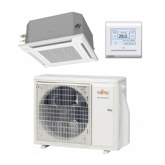
Fujitsu AUXG07KVLA Design & Technical Manual
2-unit multi-split type
Hide thumbs
Also See for AUXG07KVLA:
- Service manual (471 pages) ,
- Manual (403 pages) ,
- Design & technical manual (461 pages)
Table of Contents
Quick Links
AIR CONDITIONER
2-unit multi-split type
DESIGN & TECHNICAL MANUAL
AUXG07KVLA
AUXG09KVLA
AUXG12KVLA
AUXG14KVLA
INDOOR
ASYG07KMTB
ASYG09KMTB
ASYG12KMTB
ASYG14KMTB
AGYG09KVCA
AGYG12KVCA
AGYG14KVCA
ARXG07KSLAP
ARXG09KSLAP
ARXG12KSLAP
ARXG14KSLAP
ASYG07KMCC
ASYG09KMCC
ASYG12KMCC
ASYG14KMCC
OUTDOOR
ARXG07KLLAP
ARXG09KLLAP
ARXG12KLLAP
ARXG14KLLAP
ASYG07KETA
ASYG09KETA
ASYG12KETA
ASYG14KETA
AOYG14KBTA2
ASYG07KGTB
ASYG09KGTB
ASYG12KGTB
ASYG14KGTB
ASYG07KETA-B
ASYG09KETA-B
ASYG12KETA-B
ASYG14KETA-B
AOYG18KBTA2
DR_MU021EF_06
2021.04.19
Table of Contents

Related Manuals for Fujitsu AUXG07KVLA


Summary of Contents for Fujitsu AUXG07KVLA
- Page 1 AIR CONDITIONER 2-unit multi-split type DESIGN & TECHNICAL MANUAL AUXG07KVLA ARXG07KSLAP ARXG07KLLAP ASYG07KGTB AUXG09KVLA ARXG09KSLAP ARXG09KLLAP ASYG09KGTB AUXG12KVLA ARXG12KSLAP ARXG12KLLAP ASYG12KGTB AUXG14KVLA ARXG14KSLAP ARXG14KLLAP ASYG14KGTB INDOOR ASYG07KMTB ASYG07KMCC ASYG07KETA ASYG07KETA-B ASYG09KMTB ASYG09KMCC ASYG09KETA ASYG09KETA-B ASYG12KMTB ASYG12KMCC ASYG12KETA ASYG12KETA-B ASYG14KMTB ASYG14KMCC...
- Page 2 • Product specifications and design are subject to change without notice for future improvement. • For further details, please check with our authorized dealer. Trademarks ™ FGLair is trademark of Fujitsu General Limited in the United States, other countries or both. ™ Google Play is trademark of Google Inc. ®...
-
Page 3: Table Of Contents
CONTENTS Part 1. INDOOR UNIT................1 1. Model lineup ....................2 1-1. Connectable indoor units to each outdoor unit..............3 1-2. Indoor unit connection patterns..................4 2. Specifications....................5 2-1. Compact cassette type ....................5 2-2. Mini duct type........................6 2-3. Slim duct type ........................7 2-4. Wall mounted type ......................8 2-5. - Page 4 CONTENTS (continued) 8-5. Floor type ........................92 8-6. Sound level check point ....................94 9. Electrical characteristics ................97 10. Safety devices .....................98 11. External input and output................99 11-1.Compact cassette, Mini duct, and Slim duct types ............99 11-2.Wall mounted type (Models: ASYG07KGTB, ASYG09KGTB, ASYG12KGTB, ASYG14KGTB, ASYG07KETA, ASYG09KETA, ASYG12KETA, ASYG14KETA, ASYG07KETA-B, ASYG09KETA-B, ASYG12KETA-B, and ASYG14KETA-B) ....105 11-3.Wall mounted type (Models: ASYG07KMTB, ASYG09KMTB, ASYG12KMTB,...
- Page 5 CONTENTS (continued) 16-1.Controllers ........................222 16-2.Cassette grille ......................224 16-3.Others .........................225 17. Indoor unit installation precautions ............228 17-1.Places where prohibited for use..................228 17-2.Points to remember when installing ................228...
- Page 6 CONTENTS (continued) Part 2. OUTDOOR UNIT (2 UNITS TYPE) ........231 1. Specifications....................232 2. Dimensions....................234 2-1. Model: AOYG14KBTA2 ....................234 2-2. Model: AOYG18KBTA2 ....................235 3. Installation space ..................236 3-1. Models: AOYG14KBTA2 and AOYG18KBTA2 ............236 4. Refrigerant circuit ..................239 4-1. Model: AOYG14KBTA2 ....................239 4-2.
-
Page 7: Part 1. Indoor Unit
Part 1. INDOOR UNIT COMPACT CASSETTE TYPE: WALL MOUNTED TYPE: AUXG07KVLA ASYG07KGTB AUXG09KVLA ASYG09KGTB AUXG12KVLA ASYG12KGTB AUXG14KVLA ASYG14KGTB SLIM DUCT TYPE: ASYG07KMTB ASYG09KMTB ARXG07KLLAP ASYG12KMTB ARXG09KLLAP ASYG14KMTB ARXG12KLLAP ARXG14KLLAP ASYG07KMCC ASYG09KMCC MINI DUCT TYPE: ASYG12KMCC ARXG07KSLAP ASYG14KMCC ARXG09KSLAP ASYG07KETA ARXG12KSLAP... -
Page 8: Model Lineup
1. Model lineup Indoor unit AUXG07KVLA ARXG07KSLAP ARXG07KLLAP ASYG07KGTB AUXG09KVLA ARXG09KSLAP ARXG09KLLAP ASYG09KGTB AUXG12KVLA ARXG12KSLAP ARXG12KLLAP ASYG12KGTB AUXG14KVLA ARXG14KSLAP ARXG14KLLAP ASYG14KGTB ASYG07KMTB ASYG07KMCC ASYG07KETA ASYG07KETA-B ASYG09KMTB ASYG09KMCC ASYG09KETA ASYG09KETA-B ASYG12KMTB ASYG12KMCC ASYG12KETA ASYG12KETA-B ASYG14KMTB ASYG14KMCC ASYG14KETA ASYG14KETA-B AGYG09KVCA AGYG12KVCA AGYG14KVCA... -
Page 9: Connectable Indoor Units To Each Outdoor Unit
1-1. Connectable indoor units to each outdoor unit ●: Connectable / -: Not connectable Compact cassette Mini duct Outdoor unit AUXG07—14KVLA ARXG07—14KSLAP Btu class kW class AOYG14KBTA2 ● ● ● — ● ● ● — AOYG18KBTA2 ● ● ● ● ●... -
Page 10: Indoor Unit Connection Patterns
1-2. Indoor unit connection patterns ¢ 2 units AOYG14KBTA2 Combination no. Unit 1 Unit 2 Total AOYG18KBTA2 Combination no. Unit 1 Unit 2 Total Numbers in column Unit 1, 2, and Total indicate the indoor unit capacities as follows: 7: 7,000 Btu/h, 9: 9,000 Btu/h, 12: 12,000 Btu/h, 14: 14,000 Btu/h ..- 4 - 1-2. -
Page 11: Specifications
2. Specifications 2-1. Compact cassette type Model name AUXG07KVLA AUXG09KVLA AUXG12KVLA AUXG14KVLA Power supply 1Ø 230 V ~50 Hz Available voltage range 198—264 V Capacity kW class Input power Running current 0.15 0.19 0.22 HIGH Cooling QUIET Airflow rate HIGH... -
Page 12: Mini Duct Type
2-2. Mini duct type Model name ARXG07KSLAP ARXG09KSLAP ARXG12KSLAP ARXG14KSLAP Power supply 1Ø 230 V ~50 Hz Available voltage range 198—264 V Capacity kW class HIGH Input power QUIET Running current 0.29 0.33 0.38 0.58 HIGH Cooling QUIET Airflow rate HIGH Heating QUIET... -
Page 13: Slim Duct Type
2-3. Slim duct type Model name ARXG07KLLAP ARXG09KLLAP ARXG12KLLAP ARXG14KLLAP Power supply 1Ø 230 V ~50 Hz Available voltage range 198—264 V Capacity kW class Input power Running current 0.33 0.30 0.35 0.51 HIGH Cooling QUIET Airflow rate HIGH Heating QUIET Type ×... -
Page 14: Wall Mounted Type
2-4. Wall mounted type Model name ASYG07KGTB ASYG09KGTB ASYG12KGTB ASYG14KGTB Power supply 1Ø 230 V ~50 Hz Available voltage range 198—264 V Capacity kW class Input power Running current 0.20 0.24 0.24 0.29 HIGH Cooling QUIET Airflow rate HIGH Heating QUIET Type ×... - Page 15 Model name ASYG07KMTB ASYG09KMTB ASYG12KMTB ASYG14KMTB Power supply 1Ø 230 V ~50 Hz Available voltage range 198—264 V Capacity kW class Input power Running current 0.20 0.24 0.24 0.30 HIGH Cooling QUIET Airflow rate HIGH Heating QUIET Type × Q'ty Crossflow fan ×...
- Page 16 Model name ASYG07KMCC ASYG09KMCC ASYG12KMCC ASYG14KMCC Power supply 1Ø 230 V ~50 Hz Available voltage range 198—264 V Capacity kW class Input power Running current 0.20 0.24 0.24 0.30 HIGH Cooling QUIET Airflow rate HIGH Heating QUIET Type × Q'ty Crossflow fan ×...
- Page 17 ASYG07KETA ASYG09KETA ASYG12KETA ASYG14KETA Model name ASYG07KETA-B ASYG09KETA-B ASYG12KETA-B ASYG14KETA-B Power supply 1Ø 230 V ~50 Hz Available voltage range 198—264 V Capacity kW class Input power Running current 0.20 0.24 0.24 0.30 HIGH Cooling QUIET Airflow rate HIGH Heating QUIET Type ×...
-
Page 18: Floor Type
2-5. Floor type Model name AGYG09KVCA AGYG12KVCA AGYG14KVCA Power supply 230 V ~ 50 Hz Available voltage range 198—264 V Capacity kW class Input power Running current 0.15 0.18 0.20 HIGH Cooling QUIET Airflow rate HIGH Heating QUIET Type × Q'ty Cross flow fan ×... -
Page 19: Dimensions
3. Dimensions 3-1. Compact cassette type ¢ Models: AUXG07KVLA, AUXG09KVLA, AUXG12KVLA, and AUXG14KVLA Unit: mm Grid type grille Hanging bolt position IR receiver Drain hose View A Ceiling Control Box View C View B a: Ceiling openings Cassette grille (Option [Grid type]) - Page 20 Installation space requirement Unit: mm Strong and durable ceiling or more 1,000 1,000 or more or more 1,800 or more Obstruction Floor Maximum height from floor to ceiling (Unit: mm) 07 and 09 models 12 or larger models Standard 2,700 High ceiling —...
-
Page 21: Mini Duct Type
3-2. Mini duct type ¢ Models: ARXG07KSLAP, ARXG09KSLAP, ARXG12KSLAP, and ARXG14KSLAP Unit: mm Rear view View A Drain port P 100 × 6 = 600 Top view Side view Front view Bottom view - 15 - 3-2. Mini duct type 3. - Page 22 Installation space requirement Provide sufficient installation space for product safety. Unit: mm Strong and durable ceiling Indoor unit Left Right side side or more* or more *: 400 or more when drain from drain pipe • When intaking air from back: •...
-
Page 23: Slim Duct Type
3-3. Slim duct type ¢ Models: ARXG07KLLAP, ARXG09KLLAP, ARXG12KLLAP, and ARXG14KLLAP Unit: mm View A Rear view (Drain hose) Drain port 100 x 6 = 600 Side view Top view Front view Bottom view - 17 - 3-3. Slim duct type 3. - Page 24 Installation space requirement Provide sufficient installation space for product safety. In ceiling-concealed installations: Unit: mm 300 or more Strong and durable ceiling 20 or more Indoor unit Left Right side side 20 or more Service access Ceiling or more or more Floor ...
-
Page 25: Wall Mounted Type
3-4. Wall mounted type ¢ Models: ASYG07KGTB, ASYG09KGTB, ASYG12KGTB, and ASYG14KGTB Unit: mm (834) Outline of indoor unit for pipe inlet Ø65 for pipe inlet Ø65 - 19 - 3-4. Wall mounted type 3. Dimensions... - Page 26 Installation space requirement Provide sufficient installation space for product safety. Unit: mm 70 or more 40 or more Wall hook bracket Outline of the indoor unit 107 or more 183 or more 1,500 or more The flare connection part should be installed outdoors.
- Page 27 ¢ Models: ASYG07KMTB, ASYG09KMTB, ASYG12KMTB, ASYG14KMTB, ASYG07KMCC, ASYG09KMCC, ASYG12KMCC, and ASYG14KMCC Unit: mm (834) Outline of indoor unit for pipe inlet Ø65 for pipe inlet Ø65 - 21 - 3-4. Wall mounted type 3. Dimensions...
- Page 28 Installation space requirement Provide sufficient installation space for product safety. Unit: mm 70 or more 40 or more Wall hook bracket Outline of the indoor unit 107 or more 183 or more 1,500 or more The flare connection part should be installed outdoors.
- Page 29 ¢ Models: ASYG07KETA, ASYG09KETA, ASYG12KETA, ASYG14KETA, ASYG07KETA-B, ASYG09KETA-B, ASYG12KETA-B, and ASYG14KETA-B Unit: mm (950) Outline of indoor unit for pipe inlet Ø65 for pipe inlet Ø65 - 23 - 3-4. Wall mounted type 3. Dimensions...
- Page 30 Installation space requirement Provide sufficient installation space for product safety. Unit: mm 40 or more 40 or more Wall hook bracket Outline of the indoor unit 166 or more 211 or more 1,500 or more The flare connection part should be installed outdoors.
-
Page 31: Floor Type
3-5. Floor type ¢ Models: AGYG09KVCA, AGYG12KVCA, and AGYG14KVCA Unit: mm Side view Front view Installation space 100 or more 80 or more 80 or more 50 or more 150 or below from the floor - 25 - 3-5. Floor type 3. - Page 32 PROHIBITED Grating WARNING • The appliance shall be installed, operated and stored in a room with a floor area larger than X Minimum room area Amount of refrigerant charge M (kg) X (m M ≤ 1.22 1.22 < M ≤ 1.23 12.99 1.23 <...
-
Page 33: Wiring Diagrams
4. Wiring diagrams 4-1. Compact cassette type ¢ Models: AUXG07KVLA, AUXG09KVLA, AUXG12KVLA, and AUXG14KVLA - 27 - 4-1. Compact cassette type 4. Wiring diagrams... -
Page 34: Mini Duct Type And Slim Duct Type
4-2. Mini duct type and Slim duct type ¢ Models: ARXG07KSLAP, ARXG09KSLAP, ARXG12KSLAP, ARXG14KSLAP, ARXG07KLLAP, ARXG09KLLAP, ARXG12KLLAP, and ARXG14KLLAP WLAN adapter, Converter etc. (Option) - 28 - 4-2. Mini duct type and Slim duct type 4. Wiring diagrams... -
Page 35: Wall Mounted Type
4-3. Wall mounted type ¢ Models: ASYG07KGTB, ASYG09KGTB, ASYG12KGTB, and ASYG14KGTB - 29 - 4-3. Wall mounted type 4. Wiring diagrams... - Page 36 ¢ Models: ASYG07KMTB, ASYG09KMTB, ASYG12KMTB, and ASYG14KMTB - 30 - 4-3. Wall mounted type 4. Wiring diagrams...
- Page 37 ¢ Models: ASYG07KMCC, ASYG09KMCC, ASYG12KMCC, and ASYG14KMCC - 31 - 4-3. Wall mounted type 4. Wiring diagrams...
- Page 38 ¢ Models: ASYG07KETA, ASYG09KETA, ASYG12KETA, ASYG14KETA, ASYG07KETA-B, ASYG09KETA-B, ASYG12KETA-B, and ASYG14KETA-B - 32 - 4-3. Wall mounted type 4. Wiring diagrams...
-
Page 39: Floor Type
4-4. Floor type ¢ Models: AGYG09KVCA, AGYG12KVCA, and AGYG14KVCA - 33 - 4-4. Floor type 4. Wiring diagrams... -
Page 40: Air Velocity And Temperature Distributions
5. Air velocity and temperature distributions 5-1. Compact cassette type ¢ Models: AUXG07KVLA and AUXG09KVLA • Air velocity distribution Fan speed Operation mode Measuring conditions HIGH Unit : m/s 0.25 0.25 Top view Vertical airflow direction louver: up 0.25 0.25... - Page 41 • Air velocity distribution Fan speed Operation mode Outlet directions Measuring conditions NOTE: Reference data HIGH HEAT 4-way air outlet Unit : m/s Side view Vertical airflow direction louver: down 0.25 0.25 4 (m) • Air temperature distribution Fan speed Operation mode Outlet directions Measuring conditions...
- Page 42 ¢ Model: AUXG12KVLA • Air velocity distribution Fan speed Operation mode Measuring conditions HIGH Unit : m/s 0.25 0.25 Top view Vertical airflow direction louver: up 0.25 0.25 4 (m) Unit : m/s Side view Vertical airflow direction louver: up 0.25 0.25 4 (m)
- Page 43 • Air velocity distribution Fan speed Operation mode Outlet directions Measuring conditions NOTE:Reference data HIGH HEAT 4-way air outlet Unit : m/s Side view Vertical airflow direction louver: down 0.25 0.25 4 (m) • Air temperature distribution Fan speed Operation mode Outlet directions Measuring conditions NOTE:Reference data...
- Page 44 ¢ Model: AUXG14KVLA • Air velocity distribution Fan speed Operation mode Measuring conditions HIGH Unit : m/s 0.25 Top view Vertical airflow direction louver: up 0.25 0.25 0.25 4 (m) Unit : m/s Side view Vertical airflow direction louver: up 0.25 0.25 4 (m)
- Page 45 • Air velocity distribution Fan speed Operation mode Outlet directions Measuring conditions NOTE:Reference data HIGH HEAT 4-way air outlet Unit : m/s Side view Vertical airflow direction louver: down 0.25 4 (m) • Air temperature distribution Fan speed Operation mode Outlet directions Measuring conditions NOTE:Reference data...
-
Page 46: Mini Duct Type
5-2. Mini duct type ¢ Model: ARXG07KSLAP NOTE: This data is measured after installing optional Auto louver grille kit. • Air velocity distribution Fan speed Operation mode Measuring conditions HIGH Unit: m/s Top view Vertical airflow direction louver: Up Horizontal airflow direction louver: Center Unit: m/s Top view Vertical airflow direction louver: Up... - Page 47 • Air velocity distribution Fan speed Operation mode Measuring conditions HIGH HEAT Unit: m/s Side view Vertical airflow direction louver: Down Horizontal airflow direction louver: Center • Air temperature distribution Fan speed Operation mode Measuring conditions HIGH HEAT Unit: °C Side view Vertical airflow direction louver: Down Horizontal airflow direction louver: Center...
- Page 48 ¢ Model: ARXG09KSLAP NOTE: This data is measured after installing optional Auto louver grille kit. • Air velocity distribution Fan speed Operation mode Measuring conditions HIGH Unit: m/s Top view Vertical airflow direction louver: Up Horizontal airflow direction louver: Center Unit: m/s Top view Vertical airflow direction louver: Up...
- Page 49 • Air velocity distribution Fan speed Operation mode Measuring conditions HIGH HEAT Unit: m/s Side view Vertical airflow direction louver: Down Horizontal airflow direction louver: Center • Air temperature distribution Fan speed Operation mode Measuring conditions HIGH HEAT Unit: °C Side view Vertical airflow direction louver: Down Horizontal airflow direction louver: Center...
- Page 50 ¢ Model: ARXG12KSLAP NOTE: This data is measured after installing optional Auto louver grille kit. • Air velocity distribution Fan speed Operation mode Measuring conditions HIGH Unit: m/s Top view Vertical airflow direction louver: Up Horizontal airflow direction louver: Center Unit: m/s Top view Vertical airflow direction louver: Up...
- Page 51 • Air velocity distribution Fan speed Operation mode Measuring conditions HIGH HEAT Unit: m/s Side view Vertical airflow direction louver: Down Horizontal airflow direction louver: Center • Air temperature distribution Fan speed Operation mode Measuring conditions HIGH HEAT Unit: °C Side view Vertical airflow direction louver: Down Horizontal airflow direction louver: Center...
- Page 52 ¢ Model: ARXG14KSLAP NOTE: This data is measured after installing optional Auto louver grille kit. • Air velocity distribution Fan speed Operation mode Measuring conditions HIGH Unit: m/s Top view Vertical airflow direction louver: Up Horizontal airflow direction louver: Center Unit: m/s Top view Vertical airflow direction louver: Up...
- Page 53 • Air velocity distribution Fan speed Operation mode Measuring conditions HIGH HEAT Unit: m/s Side view Vertical airflow direction louver: Down Horizontal airflow direction louver: Center • Air temperature distribution Fan speed Operation mode Measuring conditions HIGH HEAT Unit: °C Side view Vertical airflow direction louver: Down Horizontal airflow direction louver: Center...
-
Page 54: Slim Duct Type
5-3. Slim duct type ¢ Model: ARXG07KLLAP NOTE: This data is measured after installing optional Auto louver grille kit. • Air velocity distribution Fan speed Operation mode Measuring conditions HIGH Unit: m/s Top view Vertical airflow direction louver: Up Horizontal airflow direction louver: Center Unit: m/s Top view Vertical airflow direction louver: Up... - Page 55 • Air velocity distribution Fan speed Operation mode Measuring conditions HIGH HEAT Unit: m/s Side view Vertical airflow direction louver: Down Horizontal airflow direction louver: Center • Air temperature distribution Fan speed Operation mode Measuring conditions HIGH HEAT Unit: °C Side view Vertical airflow direction louver: Down Horizontal airflow direction louver: Center...
- Page 56 ¢ Model: ARXG09KLLAP NOTE: This data is measured after installing optional Auto louver grille kit. • Air velocity distribution Fan speed Operation mode Measuring conditions HIGH Unit: m/s Top view Vertical airflow direction louver: Up Horizontal airflow direction louver: Center Unit: m/s Top view Vertical airflow direction louver: Up...
- Page 57 • Air velocity distribution Fan speed Operation mode Measuring conditions HIGH HEAT Unit: m/s Side view Vertical airflow direction louver: Down Horizontal airflow direction louver: Center • Air temperature distribution Fan speed Operation mode Measuring conditions HIGH HEAT Unit: °C Side view Vertical airflow direction louver: Down Horizontal airflow direction louver: Center...
- Page 58 ¢ Model: ARXG12KLLAP NOTE: This data is measured after installing optional Auto louver grille kit. • Air velocity distribution Fan speed Operation mode Measuring conditions HIGH Unit: m/s Top view Vertical airflow direction louver: Up Horizontal airflow direction louver: Center Unit: m/s Top view Vertical airflow direction louver: Up...
- Page 59 • Air velocity distribution Fan speed Operation mode Measuring conditions HIGH HEAT Unit: m/s Side view Vertical airflow direction louver: Down Horizontal airflow direction louver: Center • Air temperature distribution Fan speed Operation mode Measuring conditions HIGH HEAT Unit: °C Side view Vertical airflow direction louver: Down Horizontal airflow direction louver: Center...
- Page 60 ¢ Model: ARXG14KLLAP NOTE: This data is measured after installing optional Auto louver grille kit. • Air velocity distribution Fan speed Operation mode Measuring conditions HIGH Unit: m/s Top view Vertical airflow direction louver: Up Horizontal airflow direction louver: Center Unit: m/s Top view Vertical airflow direction louver: Up...
- Page 61 • Air velocity distribution Fan speed Operation mode Measuring conditions HIGH HEAT Unit: m/s Side view Vertical airflow direction louver: Down Horizontal airflow direction louver: Center • Air temperature distribution Fan speed Operation mode Measuring conditions HIGH HEAT Unit: °C Side view Vertical airflow direction louver: Down Horizontal airflow direction louver: Center...
-
Page 62: Wall Mounted Type
5-4. Wall mounted type ¢ Models: ASYG07KGTB, ASYG09KGTB, ASYG07KMTB, ASYG09KMTB, ASYG12KMTB, ASYG07KMCC, ASYG09KMCC, ASYG12KMCC, ASYG07KETA, ASYG09KETA, ASYG12KETA, ASYG07KETA-B, ASYG09KETA-B, and ASYG12KETA-B Fan speed Operation mode Measuring conditions HIGH Unit: m/s Top view Vertical airflow direction louver: Up Horizontal airflow direction louver: Center Unit: m/s Top view Vertical airflow direction louver: Up... - Page 63 ¢ Models: ASYG12KGTB, ASYG14KGTB, ASYG14KMTB, ASYG14KMCC, ASYG14KETA, and ASYG14KETA-B Fan speed Operation mode Measuring conditions HIGH Unit: m/s Top view Vertical airflow direction louver: Up Horizontal airflow direction louver: Center Unit: m/s Top view Vertical airflow direction louver: Up Horizontal airflow direction louver: Left & Right Unit: m/s Side view Vertical airflow direction louver: Up...
-
Page 64: Floor Type
5-5. Floor type ¢ Models: AGYG09KVCA, AGYG12KVCA, and AGYG14KVCA Fan speed Operation mode Fan select Measuring conditions HIGH Upper and lower Unit: m/s Top view Vertical airflow direction louver: Up Horizontal airflow direction louver: Center UPPER LOWER Unit: m/s Top view Vertical airflow direction louver: Up Horizontal airflow direction louver: Left &... -
Page 65: Fan Performance
6. Fan performance NOTE: Airflow and capacity/outlet temperature curve data are measured based on the same condi- tions mentioned in "Specifications". 6-1. Mini duct type ¢ Model: ARXG07KSLAP Quiet (SP mode 00) SP mode 03 upper limit Quiet (Normal SP) Quiet (SP mode 03) Hi (SP mode 03) Normal SP upper limit... - Page 66 Characteristics of air volume and capacity • Cooling Capacity Airflow (m • Heating Capacity Airflow (m - 60 - 6-1. Mini duct type 6. Fan performance...
- Page 67 ¢ Model: ARXG09KSLAP Quiet (SP mode 00) SP mode 03 upper limit Quiet (Normal SP) Hi (SP mode 03) Quiet (SP mode 03) SP mode 00 upper limit SP mode 03 lower limit Normal SP upper limit Hi (Normal SP) Hi (SP mode 00) Airflow (m Available airflow rate range (High level)
- Page 68 Characteristics of air volume and capacity • Cooling Capacity Airflow (m • Heating Capacity Airflow (m - 62 - 6-1. Mini duct type 6. Fan performance...
- Page 69 ¢ Model: ARXG12KSLAP SP mode 03 upper limit Quiet (SP mode 03) Hi (SP mode 03) Quiet Normal SP (Normal SP) upper limit Quiet SP mode 03 (SP mode 00) lower limit SP mode 00 (Normal SP) upper limit Hi (SP mode 00) Airflow (m Available airflow rate range (High level) Hi (SP mode 03)
- Page 70 Characteristics of air volume and capacity • Cooling Capacity Airflow (m • Heating Capacity Airflow (m - 64 - 6-1. Mini duct type 6. Fan performance...
- Page 71 ¢ Model: ARXG14KSLAP Hi (SP mode 05) SP mode 05 upper limit Quiet (SP mode 00) Nomal SP Quiet upper limit (Nomal SP) Quiet Hi (Normal SP) (SP mode 05) SP mode 05 lower limit SP mode 00 upper limit (SP mode 00) Airflow (m Available airflow rate range (High level)
- Page 72 Characteristics of air volume and capacity • Cooling Capacity Airflow (m • Heating Capacity Airflow (m - 66 - 6-1. Mini duct type 6. Fan performance...
-
Page 73: Slim Duct Type
6-2. Slim duct type ¢ Model: ARXG07KLLAP Hi (SP mode 09) SP mode 09 upper limit Quiet (SP mode 09) SP mode 09 lower limit Normal SP upper limit Quiet (Normal SP) Hi (Normal SP) SP mode 00 Normal SP upper limit lower limited Quiet (SP mode 00) - Page 74 Characteristics of air volume and capacity • Cooling Capacity Airflow (m • Heating Capacity Airflow (m - 68 - 6-2. Slim duct type 6. Fan performance...
- Page 75 ¢ Model: ARXG09KLLAP Hi (SP mode 09) SP mode 09 upper limit Quiet (SP mode 09) SP mode 09 lower limit Normal SP upper limit Quiet (Normal SP) Hi (Normal SP) Hi (SP mode00) SP mode 00 upper limit Quiet (SP mode 00) Airflow (m Available airflow rate range (High level) Hi (SP mode 09)
- Page 76 Characteristics of air volume and capacity • Cooling Capacity Airflow (m • Heating Capacity Airflow (m - 70 - 6-2. Slim duct type 6. Fan performance...
- Page 77 ¢ Model: ARXG12KLLAP SP mode 09 upper limit Hi (SP mode 09) Quiet (SP mode 09) SP mode 09 lower limit Normal SP upper limit Quiet (Normal SP) Hi (Normal SP) SP mode 00 Hi (SP mode 00) upper limit Quiet (SP mode 00) Airflow (m Available airflow rate range (High level)
- Page 78 Characteristics of air volume and capacity • Cooling Capacity Airflow (m • Heating Capacity Airflow (m - 72 - 6-2. Slim duct type 6. Fan performance...
- Page 79 ¢ Model: ARXG14KLLAP SP mode 09 upper limit Hi (SP mode 09) Quiet (SP mode 09) Nomal SP upper limit SP mode 09 lower limit Quiet (Nomal SP) Hi (Normal SP) SP mode 00 upper limit Hi (SP mode 00) Quiet (SP mode 00) 1,000...
- Page 80 Characteristics of air volume and capacity • Cooling Capacity 1,000 Airflow (m • Heating Capacity 1,000 Airflow (m - 74 - 6-2. Slim duct type 6. Fan performance...
-
Page 81: Airflow
/h = 0.2778 l/s = 0.5886 CFM • 3.6 m /h = 1 l/s • 1.699 m /h = 1 CFM 7-1. Compact cassette type Airflow Model Operation mode Fan speed High Cooling AUXG07KVLA Quiet AUXG09KVLA High Heating Quiet High Cooling Quiet AUXG12KVLA High Heating... -
Page 82: Mini Duct Type
7-2. Mini duct type Airflow Model Operation mode Fan speed High Cooling Quiet ARXG07KSLAP High Heating Quiet High Cooling Quiet ARXG09KSLAP High Heating Quiet High Cooling Quiet ARXG12KSLAP High Heating Quiet High Cooling Quiet ARXG14KSLAP High Heating Quiet - 76 - 7-2. -
Page 83: Slim Duct Type
7-3. Slim duct type Airflow Model Operation mode Fan speed High Cooling Quiet ARXG07KLLAP High Heating Quiet High Cooling Quiet ARXG09KLLAP High Heating Quiet High Cooling Quiet ARXG12KLLAP High Heating Quiet High Cooling Quiet ARXG14KLLAP High Heating Quiet - 77 - 7-3. -
Page 84: Wall Mounted Type
7-4. Wall mounted type Airflow Model Operation mode Fan speed High Cooling Quiet ASYG07KGTB High Heating Quiet High Cooling Quiet ASYG09KGTB High Heating Quiet High Cooling Quiet ASYG12KGTB High Heating Quiet High Cooling Quiet ASYG14KGTB High Heating Quiet High Cooling Quiet ASYG07KMTB High... - Page 85 Airflow Model Operation mode Fan speed High Cooling Quiet ASYG12KMTB High Heating Quiet High Cooling Quiet ASYG14KMTB High Heating Quiet High Cooling Quiet ASYG07KMCC High Heating Quiet High Cooling Quiet ASYG09KMCC High Heating Quiet High Cooling Quiet ASYG12KMCC High Heating Quiet High Cooling...
- Page 86 Airflow Model Operation mode Fan speed High Cooling ASYG07KETA Quiet ASYG07KETA-B High Heating Quiet High Cooling ASYG09KETA Quiet High ASYG09KETA-B Heating Quiet High Cooling ASYG12KETA Quiet ASYG12KETA-B High Heating Quiet High Cooling ASYG14KETA Quiet High ASYG14KETA-B Heating Quiet - 80 - 7-4.
-
Page 87: Floor Type
7-5. Floor type Airflow Model Operation mode Fan speed High Cooling Quiet AGYG09KVCA High Heating Quiet High Cooling Quiet AGYG12KVCA High Heating Quiet High Cooling Quiet AGYG14KVCA High Heating Quiet - 81 - 7-5. Floor type 7. Airflow... -
Page 88: Noise Level Curve
8. Noise level curve 8-1. Compact cassette type ¢ Model: AUXG07KVLA Cooling Heating NC-65 NC-65 NC-60 NC-60 NC-55 NC-55 NC-50 NC-50 HIGH NC-45 NC-45 HIGH NC-40 NC-40 NC-35 NC-35 NC-30 NC-30 NC-25 NC-25 QUIET QUIET NC-20 NC-20 NC-15... - Page 89 ¢ Model: AUXG12KVLA Cooling Heating NC-65 NC-65 NC-60 NC-60 NC-55 NC-55 NC-50 NC-50 HIGH NC-45 NC-45 HIGH NC-40 NC-40 NC-35 NC-35 NC-30 NC-30 NC-25 NC-25 QUIET QUIET NC-20 NC-20 NC-15 NC-15 1,000 2,000 4,000 8,000 1,000 2,000 4,000 8,000 Octave band center frequency, Hz Octave band center frequency, Hz...
-
Page 90: Mini Duct Type
8-2. Mini duct type ¢ Model: ARXG07KSLAP Cooling Heating NC-65 NC-65 NC-60 NC-60 NC-55 NC-55 NC-50 NC-50 NC-45 NC-45 NC-40 NC-40 HIGH NC-35 NC-35 HIGH NC-30 NC-30 NC-25 NC-25 NC-20 NC-20 NC-15 NC-15 QUIET QUIET 1,000 2,000 4,000 8,000 1,000 2,000... - Page 91 ¢ Model: ARXG12KSLAP Cooling Heating NC-65 NC-65 NC-60 NC-60 NC-55 NC-55 NC-50 NC-50 NC-45 NC-45 NC-40 NC-40 NC-35 NC-35 HIGH HIGH NC-30 NC-30 NC-25 NC-25 NC-20 NC-20 QUIET QUIET NC-15 NC-15 1,000 2,000 4,000 8,000 1,000 2,000 4,000 8,000 Octave band center frequency ,Hz Octave band center frequency ,Hz...
-
Page 92: Slim Duct Type
8-3. Slim duct type ¢ Model: ARXG07KLLAP Cooling Heating NC-65 NC-65 NC-60 NC-60 NC-55 NC-55 NC-50 NC-50 NC-45 NC-45 NC-40 NC-40 NC-35 NC-35 HIGH HIGH NC-30 NC-30 NC-25 NC-25 QUIET QUIET NC-20 NC-20 NC-15 NC-15 1,000 2,000 4,000 8,000 1,000 2,000... - Page 93 ¢ Model: ARXG12KLLAP Cooling Heating NC-65 NC-65 NC-60 NC-60 NC-55 NC-55 NC-50 NC-50 NC-45 NC-45 NC-40 NC-40 HIGH HIGH NC-35 NC-35 NC-30 NC-30 NC-25 NC-25 QUIET NC-20 NC-20 QUIET NC-15 NC-15 1,000 2,000 4,000 8,000 1,000 2,000 4,000 8,000 Octave band center frequency, Hz Octave band center frequency, Hz...
-
Page 94: Wall Mounted Type
8-4. Wall mounted type ¢ Model: ASYG07KGTB Cooling Heating NC-65 NC-65 NC-60 NC-60 NC-55 NC-55 NC-50 NC-50 NC-45 NC-45 HIGH HIGH NC-40 NC-40 NC-35 NC-35 NC-30 NC-30 NC-25 NC-25 NC-20 NC-20 NC-15 NC-15 QUIET QUIET 1,000 2,000 4,000 8,000 1,000 2,000... - Page 95 ¢ Model: ASYG12KGTB Cooling Heating NC-65 NC-65 NC-60 NC-60 NC-55 NC-55 NC-50 NC-50 HIGH NC-45 NC-45 HIGH NC-40 NC-40 NC-35 NC-35 NC-30 NC-30 NC-25 NC-25 NC-20 NC-20 NC-15 NC-15 QUIET QUIET 1,000 2,000 4,000 8,000 1,000 2,000 4,000 8,000 Octave band center frequency, Hz Octave band center frequency, Hz...
- Page 96 ¢ Models: ASYG07KMTB, ASYG07KMCC, ASYG07KETA, and ASYG07KETA-B Cooling Heating NC-65 NC-65 NC-60 NC-60 NC-55 NC-55 NC-50 NC-50 HIGH NC-45 NC-45 HIGH NC-40 NC-40 NC-35 NC-35 NC-30 NC-30 NC-25 NC-25 NC-20 NC-20 QUIET NC-15 NC-15 QUIET 1,000 2,000 4,000 8,000 1,000 2,000...
- Page 97 ¢ Models: ASYG12KMTB, ASYG12KMCC, ASYG12KETA, and ASYG12KETA-B Cooling Heating NC-65 NC-65 NC-60 NC-60 NC-55 NC-55 NC-50 NC-50 HIGH NC-45 NC-45 HIGH NC-40 NC-40 NC-35 NC-35 NC-30 NC-30 NC-25 NC-25 NC-20 NC-20 QUIET NC-15 NC-15 QUIET 1,000 2,000 4,000 8,000 1,000 2,000...
-
Page 98: Floor Type
8-5. Floor type ¢ Model: AGYG09KVCA Cooling Heating NC-65 NC-65 NC-60 NC-60 NC-55 NC-55 HIGH HIGH NC-50 NC-50 NC-45 NC-45 NC-40 NC-40 NC-35 NC-35 NC-30 NC-30 NC-25 NC-25 QUIET QUIET NC-20 NC-20 NC-15 NC-15 1,000 2,000 4,000 8,000 1,000 2,000 4,000... - Page 99 ¢ Model: AGYG14KVCA Cooling Heating NC-65 NC-65 NC-60 NC-60 HIGH NC-55 NC-55 HIGH NC-50 NC-50 NC-45 NC-45 NC-40 NC-40 NC-35 NC-35 NC-30 NC-30 NC-25 NC-25 QUIET QUIET NC-20 NC-20 NC-15 NC-15 1,000 2,000 4,000 8,000 1,000 2,000 4,000 8,000 Octave band center frequency, Hz Octave band center frequency, Hz...
-
Page 100: Sound Level Check Point
8-6. Sound level check point ¢ Compact cassette type Microphone 1.5 m Microphone - 94 - 8-6. Sound level check point 8. Noise level curve... - Page 101 ¢ Mini duct type Measuring duct Measuring duct Set the static pressure as rating in this area Microphone Microphone Side view Front view ¢ Slim duct type Measuring duct Measuring duct Set the static pressure as rating in this area Microphone Microphone Side view...
- Page 102 ¢ Floor type Microphone Microphone ● ● Airflow Airflow - 96 - 8-6. Sound level check point 8. Noise level curve...
-
Page 103: Electrical Characteristics
Indoor rated (50 Hz, 230 V) (Indoor unit to outdoor unit) Cross- Limited Input sectional wiring power Type Model name area length AUXG07KVLA 0.19 0.15 AUXG09KVLA 0.19 0.15 Compact cassette AUXG12KVLA 0.24 0.19 AUXG14KVLA 0.28 0.22 ARXG07KSLAP 0.33 0.29 ARXG09KSLAP 0.38... -
Page 104: Safety Devices
10. Safety devices Terminal Indoor unit Float Model name PCB* fuse Fan motor thermal protector thermal type switch fuse AUXG07KVLA Activate: 100 ±10 °C Fan motor stop AUXG09KVLA Compact cassette Reset: 95 ±10 °C AUXG12KVLA Fan motor restart AUXG14KVLA ARXG07KSLAP Activate: 135 ±15 °C... -
Page 105: External Input And Output
11. External input and output 11-1. Compact cassette, Mini duct, and Slim duct types Exterior of the indoor unit PCB and the component location differ by the type of the indoor unit as follows. • Compact cassette type: Indoor unit PCB CN47 (Ext. - Page 106 ¢ External input With using external input function, some functions on this product can be controlled from an external device. • “Operation/Stop” mode or "Forced stop" mode can be selected with function setting of indoor unit. • A twisted pair cable (22AWG) should be used. Maximum length of cable is 150 m. •...
- Page 107 ¢ Combination of external input and output By combining the function setting of the indoor unit, you can select various combinations of func- tions. Combination examples of external input and output are as follows: External input External output Mode Function setting Terminal CN47 60—00...
- Page 108 ¢ Details of function Control input function • When function setting is "Operation/Stop" mode 1 Function setting External input Input signal Command Off → On Operation 46—00 Terminal On → Off Stop Input Operation Indoor unit Stop Remote controller NOTES: •...
- Page 109 • When function setting is "Operation/Stop" mode 2 Function setting External input Input signal Command Off → On Operation 46—03 Terminal On → Off Stop (R.C. disabled) Input Operation Indoor unit Stop (R.C. disabled) Remote controller NOTE: When "Operation/Stop" mode 2 function is used with forming a remote controller group, connect the same equipment to each indoor unit within the group.
- Page 110 Indoor unit fan operation status Function setting External output Output signal Command Low → High Fan run 60—10 CN47 High → Low Fan stop Output signal Condition The indoor unit fan is operating. Low → High The fan is stopped or during cold air prevention. During thermostat off when in dry mode operation.
-
Page 111: 11-2.Wall Mounted Type
11-2. Wall mounted type (Models: ASYG07KGTB, ASYG09KGTB, ASYG12KGTB, ASYG14KGTB, ASYG07KETA, ASYG09KETA, ASYG12KETA, ASYG14KETA, ASYG07KETA-B, ASYG09KETA-B, ASYG12KETA-B, and ASYG14KETA-B) External input and output PCB SW301 SW302 Rotary switch CN314 CN313 CN312 CN311 CN310 CN308 To CN6 on Indoor unit PCB Input External input External output Connector... - Page 112 ¢ External input With using external input function, some functions on this product can be controlled from an external device. • “Operation/Stop” mode or "Forced stop" mode can be selected with function setting of indoor unit. • A twisted pair cable should be used. Maximum length of cable is 150 m. •...
- Page 113 ¢ External output Use an external output cable with appropriate external dimension, depending on the number of ca- bles to be installed. External input and output PCB • A twisted pair cable (22AWG) should be used. Maximum length of cable is 25 m. •...
- Page 114 ¢ Combination of external input and output By combining the function setting of the indoor unit and rotary switch setting of the External input and output PCB, you can select various combinations of functions. Combination examples of external input and output are as follows: External input External input Function...
- Page 115 Input signal type External input and output PCB: The input signal type can be selected. Signal type (edge or pulse) can be switched by the DIP switch SW302 on the External input and out- put PCB. The width of pulse must be longer than 200 msec.
- Page 116 ¢ Details of function Control input function • When function setting is "Operation/Stop" mode 1 – In the case of "Edge" input: Rotary SW on Function External input and External input Input signal Command setting / output PCB Off → On Operation External input and 46-00...
- Page 117 • When function setting is "Forced stop" mode – In the case of "Edge" input: Rotary SW on Function External input and External input Input signal Command setting / output PCB Off → On Forced stop External input and 46-02 60-00 / 1 CN313 output PCB...
- Page 118 • When function setting is "Operation/Stop" mode 2 – In the case of "Edge" input: Rotary SW on Function External input and External input Input signal Command setting / output PCB Off → On Operation External input and 46-03 60-00 / 1 CN313 Stop (R.C.
- Page 119 • Forced thermostat off function Rotary SW on Function External input and External input Input signal Command setting / output PCB Thermostat 60-00 / 2 Off → On External input and output 60-09 / B CN313 Normal 60-10 / C On →...
- Page 120 Control output function • Operation/Stop status Rotary SW on Function Output External input and External output Command setting / signal output PCB Off → On Operation External input and output 60-00 / 1 CN310 On → Off Stop The output is low when the unit is stopped. Operation Indoor unit Stop...
-
Page 121: 11-3.Wall Mounted Type (Models: Asyg07Kmtb, Asyg09Kmtb, Asyg12Kmtb, Asyg14Kmtb, Asyg07Kmcc, Asyg09Kmcc, Asyg12Kmcc, And Asyg14Kmcc)
11-3. Wall mounted type (Models: ASYG07KMTB, ASYG09KMTB, ASYG12KMTB, ASYG14KMTB, ASYG07KMCC, ASYG09KMCC, ASYG12KMCC, and ASYG14KMCC) With using external input and output functions, this product can be operated inter-connectedly with an external device. Connector Input Output Remarks CNA01 Control input — See external input/output CNB01 —... - Page 122 • Circuit diagram example • Contact capacity: DC 24 V or more, 10 Indoor unit mA or more. Communication kit Connected unit control PCB • *: Make the distance from the PCB to Example: Switch Connector the connected unit within 10 m. •...
- Page 123 • Optional part Part name Model name Exterior External input wire External connect kit UTY-XWZXZ5 Communication kit UTY-TWBXF2 * For operating the external function, the wall mounted type requires the communication kit in addi- tion to the wire (UTY-XWZXZ5). - 117 - 11-3.
- Page 124 ¢ External output With using external output function, operating status of this product can be transmitted to the exter- nal device, and also, this product can be inter-connected with the external device. Operation status output Air conditioner operation status signal can be output. •...
- Page 125 Error status output Air conditioner error status signal can be output. • Circuit diagram example: Indoor unit control PCB Communication kit Connected unit Connector DC 24 V Example: Relay unit Example: Display Relay power supply 10 m* Signal Optional parts Locally purchased –...
-
Page 126: 11-4.Floor Type
11-4. Floor type Indoor unit PCB CN 23 CN 21 CN 15 CN 14 P 190 External input External output Connector Input signal Operation/Stop CN14 Forced stop — Edge Forced thermostat off CN15 Operation status Indoor unit Error status CN20/CN21/ —... - Page 127 ¢ External output Use an external output cable with appropriate external dimension, depending on the number of ca- bles to be installed. Indoor unit • A twisted pair cable (22AWG) should be used. Maximum length of cable is 25 m . •...
- Page 128 ¢ Combination of external input and output By combining the function setting of the indoor unit, you can select various combinations of func- tions. Combination examples of external input and output are as follows: External input Function Mode Indoor unit setting CN14 CN15...
- Page 129 ¢ Details of function Control input function • When function setting is "Operation/Stop" mode 1 – In the case of "Edge" input Mode Function setting External input Input signal Command Off → On Operation — CN14 On → Off Stop 46-00 Input of indoor unit...
- Page 130 • When function setting is "Operation/Stop"mode 2 – In the case of "Edge" input Mode Function setting External input Input signal Command Off → On Operation — CN14 Stop (R.C. On → Off disabled) 46-03 Input of indoor unit Off → On Operation 60-00 CN15...
- Page 131 Control output function • Operation/Stop status Output Mode Function setting External output Command signal Low → High Operation 60-00 CN15 High → Low Stop Output of indoor unit Off → On Operation 60-00 CN20 On → Off Stop The output is low when the unit is stopped. Operation Indoor unit Stop...
- Page 132 • Indoor unit fan operation status Output Mode Function setting External output Command signal Low → High Fan run 60-10 CN15 High → Low Fan stop Output of indoor unit Off → On Fan run 60-00 CN22 On → Off Fan stop Output signal Condition...
- Page 133 • Design and install external heater appropriately with considering its protection. • Inappropriate designing and installation of external heater may cause a fire by emitted heat from the external heater. • Fujitsu General Ltd. is not responsible for inappropriate designing or installation of external heating device. - 127 - 11-4.
- Page 134 • Auxiliary heater control 1 Operation Condition Heater on Heater is on as shown in following diagram of heating temperature. • Heater is off as shown in following diagram of heating temperature. • Other than heating mode Heater off • Error occurred •...
-
Page 135: Group Connection
12. Group connection NOTE: Group control cannot be used together with Wireless LAN adapter. Installation procedure for group control system: A number of indoor units can be operated at the same time using a single remote controller. NOTE: When different type of indoor units (such as wall mounted type and cassette type, cassette type and duct type, or other combinations) are connected using group control system, some functions may no longer be available. - Page 136 2. Set the R.C. address. (Function setting) • Addresses will be automatically set when initially starting up this unit. In such a case, do not change the remote controller address for the indoor unit, and keep it at the initial setting of “00”.
-
Page 137: Remote Controller
13. Remote controller 13-1. Wireless remote controller (AR-REW4E, AR-REM4E, and AR-REB1E) ¢ Overview • AR-REW4E Signal transmitter MODE button FAN button 10°C HEAT button SWING button ECONOMY button TEMP. button OUTDOOR UNIT SET button LOW NOISE button POWERFUL button WEEKLY button TIMER SETTING button Start/Stop button... - Page 138 To facilitate explanation, the accompanying illustration has been drawn to show all possible indicators; in actual operation, however, the display will only show those indicators appropriate to the current oper- ation. • AR-REM4E Signal SENSOR button transmitter MODE button FAN button 10°C HEAT button SWING button...
- Page 139 • AR-REB1E Signal transmitter MODE button FAN button 10°C HEAT button ECONOMY button SWING button OUTDOOR UNIT SET button LOW NOISE button TEMP. button ON TIMER button POWERFUL button OFF TIMER button Start/Stop button TIMER SELECT button RESET button SLEEP TIMER button CLOCK ADJUST button TIMER CANCEL button NOTE: Functions may differ by type of the indoor unit.
- Page 140 ¢ Specifications Controller Unit: mm Top view Front view Side view Size (H × W × D) 205 × 61 × 17 Weight 124 (without batteries) Holder Unit: mm 48.5 Ø 3.5 (Hole) Hole 26.2 69.3 Front View Side View Bottom View Size (H ×...
-
Page 141: 13-2.Wireless Remote Controller (Ar-Rem7E)
13-2. Wireless remote controller (AR-REM7E) ¢ Overview Signal transmitter MODE button FAN button 10 °C HEAT button SWING button ECONOMY button TEMP. button OUTDOOR UNIT SET button LOW NOISE button POWERFUL button WEEKLY button TIMER SETTING button Start/Stop button ON/OFF button SEND button SLEEP button SELECT button... - Page 142 ¢ Specifications Controller Unit: mm Top view Front view Side view Size (H × W × D) 205 × 61 × 17 Weight 124 (without batteries) Holder Unit: mm 48.5 Ø 3.5 (Hole) Hole 26.2 69.3 Front View Side View Bottom View Size (H ×...
-
Page 143: 13-3.Wireless Remote Controller (Uty-Lnty: Optional Part)
13-3. Wireless remote controller (UTY-LNTY: Optional part) ¢ Overview Signal transmitter MODE button FAN button 10°C HEAT button TEMP. SWING button button SET button Economy button ON TIMER button OFF TIMER button Start/Stop button REG1U TIMER SELECT button RESET button SLEEP TIMER button TEST RUN button TIMER CANCEL button... - Page 144 ¢ Specifications Controller Unit: mm Top view Front view Side view Size (H × W × D) 205 × 61 × 17 Weight 124 (without batteries) Holder Unit: mm 48.5 Ø 3.5 (Hole) Hole 26.2 69.3 Front View Side View Bottom View Size (H ×...
-
Page 145: 13-4.Ir Receiver Kit With Wireless Remote Controller (Uty-Lbtym: Optional Part)
13-4. IR receiver kit with Wireless remote controller (UTY- LBTYM: Optional part) ¢ Overview Signal transmitter FAN button MODE button 10°C HEAT button TEMP. SWING button button SET button Economy button ON TIMER button OFF TIMER button Start/Stop button REG1U TIMER SELECT button RESET button SLEEP TIMER button... - Page 146 ¢ Specifications Controller Unit: mm Top view Front view Side view Size (H × W × D) 205 × 61 × 17 Weight 124 (without batteries) Holder Unit: mm 48.5 Ø 3.5 (Hole) Hole 26.2 69.3 Front View Side View Bottom View Size (H ×...
- Page 147 IR receiver Unit: mm 13.6 57.4 13.6 11.5 18.5 Front view Side view Rear view Size (H × W × D) 145 × 90 × 30 Weight - 141 - 13-4. IR receiver kit with Wireless remote controller (UTY-LBTYM: Optional part) 13.
-
Page 148: 13-5.Wired Remote Controller (Uty-Rnnym: Optional Part)
13-5. Wired remote controller (UTY-RNNYM: Optional part) ¢ Overview a START/STOP button Starts and stops operation. b SET TEMP. button Selects the setting temperature. c MODE button Selects the operating mode (AUTO , HEAT ,FAN COOL , and DRY d FAN button Selects the fan speed AUTO ,QUIET , LOW... - Page 149 ¢ System diagram 1 remote controller: 2 remote controllers: Indoor unit Indoor unit A, B, C: Remote controller cable A ≤ 500 m;B + C ≤ 500 m Primary Secondary Remote controllers Remote controller ¢ Electrical wiring 1 remote controller: 2 remote controllers: Indoor unit Indoor unit...
- Page 150 ¢ Specifications Dimensions and other specifications on the wired remote controller are as follows. Unit: mm Front view Side view Size (H × W × D) 120 × 120 × 18 Weight Cable length (accessory) Power Wiring specifications Cable size Wire type Remarks Remote controller cable...
- Page 151 When connecting to Communication kit (for KM models in Wall mounted type) When connecting the remote controller to optional Communication kit, follow the procedures men- tioned below. Modify the remote controller cable as follows: • Use a tool to cut off the terminal on the end of the remote controller cable and then remove the insulation from the cut end of the cable as shown in following figure.
-
Page 152: 13-6.Wired Remote Controller (Uty-Rlry: Optional Part)
13-6. Wired remote controller (UTY-RLRY: Optional part) ¢ Overview a LED lamp (Operation indicator) Lights while the indoor unit is operating. Blinks when an error occurred. b FAN button Each time the button is pressed, fan speed switches as follows: Auto High Quiet... - Page 153 ¢ System diagram 1 remote controller: 2 remote controllers: Indoor unit Indoor unit A, B, C: Remote controller cable A ≤ 500 m;B + C ≤ 500 m Primary Secondary Remote controllers Remote controller ¢ Electrical wiring 1 remote controller: 2 remote controllers: Indoor unit Indoor unit...
- Page 154 ¢ Specifications Dimensions and other specifications on the wired remote controller are as follows. Unit: mm Hole: 9 × 4.5 Hole: 12.5 × 4.5 Hole: 6 × 4.5 Front view Side view Rear view Size (H × W × D) 120 ×...
-
Page 155: 13-7.Wired Remote Controller (Uty-Rvnym: Optional Part)
13-7. Wired remote controller (UTY-RVNYM: Optional part) ¢ Overview a Display panel (with backlight) b Screen switch button (Left) c Menu button d Cancel button e Cursor button f Screen switch button (Right) g Power indicator h On/off button i Enter button - 149 - 13-7. - Page 156 ¢ System diagram 1 remote controller: 2 remote controllers: Indoor unit Indoor unit A, B, C: Remote controller cable A ≤ 500 m;B + C ≤ 500 m Primary Secondary Remote controllers Remote controller ¢ Electrical wiring 1 remote controller: 2 remote controllers: Indoor unit Indoor unit...
- Page 157 ¢ Specifications Unit: mm 21.3 Front view Side view Size (H × W × D) 120 × 120 × 21.3 Weight Wiring specifications Cable size Wire type Remarks Remote controller cable Polar 3 core Use sheathed PVC cable. 0.33 mm - 151 - 13-7.
- Page 158 ¢ Installation (Remote control main unit) Installation space: Unit : mm or more or more or more 220 or more* NOTE: Secure enough space where a flat-blade screwdriver to remove the case can be inserted. Installation procedures: 1. Process the remote controller cable. Unit : mm 1.
- Page 159 3. Attach the remote controller. • When attaching to switch box: a. Seal the wiring hole of the remote controller cable. b. Put a remote controller cable through the hole of the rear case. c. Fix the rear case by securing it with attached screws (2 places). •...
- Page 160 4. Connect the cable to the terminals on the front case. Fix the cable together with the sheath with the cable tie. Cut off the excess cable tie. Tightening torque Terminal screw 0.8 to 1.2 N•m 1. 12V (Red) 2. Signal (White) 3.
- Page 161 5. Attach the front case. • Insert after adjusting upper part of front case. • When insert the front case, do not pinch the cable. Front case Click! Good Prohibited Prohibited Prohibited CAUTION Insert the upper case firmly. If improperly attached, it will cause the upper case to fall off. ¢...
- Page 162 When connecting to Communication kit (for KM models in Wall mounted type) When connecting the remote controller to optional Communication kit, follow the procedures men- tioned below. Modify the remote controller cable as follows: • Use a tool to cut off the terminal on the end of the remote controller cable and then remove the insulation from the cut end of the cable as shown in following figure.
-
Page 163: 13-8.Wired Remote Controller (Uty-Rnryz*: Optional Part)
13-8. Wired remote controller (UTY-RNRYZ*: Optional part) ¢ Overview a Remote temperature sensor (inside) b On/off button Operable only while displaying the “Monitor mode” screen. c LED lamp (operation indicator) d Touch panel display e Set temperature Operating temperature can be set. f Remote controller group name g Mode Operation mode can be set. - Page 164 ¢ System diagram 1 remote controller: 2 remote controllers: Indoor unit Indoor unit A, B, C: Remote controller cable A ≤ 500 m;B + C ≤ 500 m Primary Secondary Remote controllers Remote controller ¢ Electrical wiring 1 remote controller: 2 remote controllers: Indoor unit Indoor unit...
- Page 165 ¢ Specifications Dimensions and other specifications on the wired remote controller are as follows. [Unit : mm] 20.4 Model name UTY-RNRYZ* Display 3.8-inch FSTN LCD (255 × 160 dots) with touch panel Dimensions (H × W × D) 120 × 120 × 20.4 Weight Input voltage DC 12...
-
Page 166: 13-9.Simple Remote Controller (Uty-Rsnym: Optional Part)
13-9. Simple remote controller (UTY-RSNYM: Optional part) ¢ Overview a START/STOP button Starts and stops operation. b Display backlight button Lights during operation. c Operation lamp Lights during operation. d FAN button Selects the fan speed (AUTO ,HIGH , MED , and QUIET ). - Page 167 ¢ System diagram 1 remote controller: 2 remote controllers: Indoor unit Indoor unit A, B, C: Remote controller cable A ≤ 500 m;B + C ≤ 500 m Primary Secondary Remote controllers Remote controller ¢ Electrical wiring 1 remote controller: 2 remote controllers: Indoor unit Indoor unit...
- Page 168 ¢ Specifications Dimensions and other specifications on the wired remote controller are as follows. Unit: mm hole x 2 hole x 2 Front View Side View Rear View Size (H × W × D) 120 × 75 × 14 Weight Cable length (accessory) Power ...
- Page 169 When connecting to Communication kit (for KM models in Wall mounted type) When connecting the remote controller to optional Communication kit, follow the procedures men- tioned below. Modify the remote controller cable as follows: • Use a tool to cut off the terminal on the end of the remote controller cable and then remove the insulation from the cut end of the cable as shown in following figure.
-
Page 170: 13-10.Simple Remote Controller (Uty-Rsry And Uty-Rhry: Optional Parts)
13-10. Simple remote controller (UTY-RSRY and UTY-RHRY: Optional parts) ¢ Overview a LED lamp Lights during operation. b Louver button Adjusts the airflow direction. c START/STOP button Starts and stops operation. d FAN control button Switches the fan speed as follows: Auto High Quiet... - Page 171 ¢ System diagram 1 remote controller: 2 remote controllers: Indoor unit Indoor unit A, B, C: Remote controller cable A ≤ 500 m;B + C ≤ 500 m Primary Secondary Remote controllers Remote controller ¢ Electrical wiring 1 remote controller: 2 remote controllers: Indoor unit Indoor unit...
- Page 172 ¢ Specifications Dimensions and other specifications on the wired remote controller are as follows. Unit: mm 30.0 30.0 Hole: 9 × 4.5 23.0 Hole: 6 × 4.5 Hole: 12.5 × 4.5 Front View Side View Rear View Size (H × W × D) 120 ×...
-
Page 173: Function Settings
14. Function settings To adjust the functions of this product according to the installation environment, various types of function settings are available. NOTE: Incorrect settings can cause a product malfunction. 14-1. Compact cassette, Mini duct, Slim duct types indoor unit (setting by DIP switch) By using some components on the PCB, you can change the function settings. - Page 174 ¢ DIP switch setting • SW100: Remote controller address setting When operating a number of indoor units by using a wired remote controller, DIP switch set- ting for assigning unit number to each indoor unit is required. The slide switches are normally set to make the unit number 00. Remote Switch number controller...
-
Page 175: 14-2.Indoor Unit (Setting By Wireless Remote Controller)
14-2. Indoor unit (setting by wireless remote controller) CAUTION This setting changes the function settings used to control the indoor unit according to the installa- tion conditions. Incorrect settings can cause a product malfunction. • After the power is turned on, perform the “Function setting” according to the installation conditions using the remote controller. - Page 176 ¢ AR-REM4E (for Wall mounted type KGTB), AR-REW4E (for Wall mounted type KETA) Button name and function During address setting mode, indoor unit reject the any operation command from remote con- troller. Function number Refer to Function details Setting number Refer to Function details 10°C HEAT button POWERFUL button...
- Page 177 Select the function number by pressing the or the buttons. Each time the 10 °C HEAT button is pressed, it switches between the right digit and the left digit. Change digit Change digit Proceed to the setting number by pressing the POWERFUL button. (To return to the function number selection, press the POWERFUL button again.) Select the function number by pressing the or the...
- Page 178 Press the button once to transmit the function setting information. 2 short beeps will be emitted from the indoor unit when the signal is received correctly. If wrong code is set, no beep sound will be emitted. 2 short beeps NOTE: Press button within 30 seconds after pressing MODE button.
- Page 179 Resetting the power after setting up all indoor units Important: • If the reset is not performed, function cannot be read correctly. • After all the functions have been set, the circuit breaker needs to be switched off for at least 2 minutes.
- Page 180 Remote controller custom code setting Custom code setting of wireless remote controller needs to be same as the setting of the indoor unit. When you change the custom code setting of the wireless remote controller, do as follows: Press the START/STOP button until only the clock is displayed on the display. Press the MODE button for at least 5 seconds to display the current custom code (initially set to Press the TEMP.
- Page 181 ¢ AR-REB1E (for Wall mounted type KMTB) Button name and function During address setting mode, indoor unit reject the any operation command from remote con- troller. Function number Refer to Function details. Setting number Refer to Function details. 10°C HEAT button POWERFUL button Changes the displayed digits.
- Page 182 Select the function number by pressing the or the buttons. Each time the 10°C HEAT button is pressed, it switches between the right digit and the left digit. Change digit Change digit Proceed to the setting number by pressing the POWERFUL button. (To return to the function number selection, press the POWERFUL button again.) Select the function number by pressing the or the...
- Page 183 Press the button once to transmit the function setting information. 2 short beeps will be emitted from the indoor unit when the signal is received correctly. If wrong code is set, no beep sound will be emitted. 2 short beeps NOTE: Press button within 30 seconds after pressing MODE button.
- Page 184 Resetting the power after setting up all indoor units Important: • If the reset is not performed, function cannot be read correctly. • After all the functions have been set, the circuit breaker needs to be switched off for at least 2 minutes.
- Page 185 Remote controller custom code setting Custom code setting of wireless remote controller needs to be same as the setting of the indoor unit. When you change the custom code setting of the wireless remote controller, do as follows: Press the START/STOP button until only the clock is displayed on the display. Press the MODE button for at least 5 seconds to display the current custom code (initially set to Press the SET TEMP.
- Page 186 ¢ UTY-LNTY (for Compact cassette type) or AR-REJ1E (included in UTY-LBTYM for Duct type) Button name and function During address setting mode, indoor unit reject the any operation command from remote con- troller. Function number Refer to Function details. Setting number Refer to Function details.
- Page 187 Select the function number by pressing the or the buttons. Each time the 10°C HEAT button is pressed, it switches between the right digit and the left digit. Change digit Change digit Proceed to the setting number by pressing the ECONOMY button. (To return to the function number selection, press the ECONOMY button again.) Select the function number by pressing the or the...
- Page 188 Press the button once to transmit the function setting information. 1 short beep will be emit- ted from the indoor unit or the IR receiver when the signal is received correctly. If wrong code is set, no beep sound will be emitted. 1 short beep NOTE: Press button within 30 seconds after pressing MODE button.
- Page 189 Setting up each indoor unit Repeat step from 1. to 8. to set up each indoor unit. If the custom code is other than " ", steps from 1. to 2. and 8. need to be performed. Resetting the power after setting up all indoor units Important: •...
- Page 190 Remote controller custom code setting Custom code setting of wireless remote controller needs to be same as the setting of the indoor unit. When you change the custom code setting of the wireless remote controller, do as follows: Press the START/STOP button until only the clock is displayed on the display. Press the MODE button for at least 5 seconds to display the current custom code (initially set to Press the SET TEMP.
-
Page 191: 14-3.Indoor Unit (Setting By Wired Remote Controller)
14-3. Indoor unit (setting by wired remote controller) • The function settings of the control of the indoor unit can be changed by this procedure according to the installation conditions. Incorrect settings can cause the indoor unit malfunction. • After the power is turned on, perform the “Function setting” according to the installation conditions using the remote controller. - Page 192 ¢ UTY-RNNYM Button name and function During address setting mode, indoor unit reject the any operation command from remote controller. Function number Refer to Function details Remote controller address Setting number Refer to Function details Λ SET TEMP. “V” and “ ”...
- Page 193 Confirm the setting by pressing the TIMER SET button. The data will be transferred to the indoor unit. Not good Good ● Data is not set up on the indoor unit Data is correctly set up on the indoor unit correctly (-- is displayed.) (Flashing display changes to illuminated display.) ●...
- Page 194 ¢ UTY-RLRY Setting procedure by using wired remote controller The function number and the associated setting value are displayed on the LCD of the remote con- troller. Follow the instructions written in the local setup procedure supplied with the remote controller, and select appropriate setting according to the installation environment.
- Page 195 Pressing the "+" or "-" button, to select the function number. Then press the "ENTER" button. Function number Pressing the "+" or "-" button, to select the setting number. Then press the "ENTER" button. Setting number Example: Function number 30 Setting number 01 Error Good...
- Page 196 ¢ UTY-RVNYM Function setting procedure Connect the power supply of the outdoor unit. Switch to the function setting mode. When [Menu button] is pressed twice while “Monitor” screen is displayed, it switches to the “Submenu” screen. If [Menu button] is pressed while the “Submenu” screen is displayed, the display returns to the “Monitor”...
- Page 197 Select the [Function No.] with pressing the [Cursor button (Left/Right)], and select the Function No. to be set with pressing the [Cursor button (Up/Down)]. Function setting Mo 10:00AM R.C. Function Setting address Cancel: Version Error history Select the [Setting No.] with pressing the [Cursor button (Left/Right)], and select the Setting No. to be set with pressing the [Cursor button (Up/Down)].
- Page 198 When [Cancel button] is pressed twice while “Function setting” screen is displayed, it switches to the “Submenu” screen. Function setting Mo 10:00AM R.C. Function Setting Submenu Mo 10:00AM address Date and time Screen Cancel: Filter sign Version Error history R.C. sensor control Room temp.
- Page 199 ¢ UTY-RNRYZ* Setting procedure by using wired remote controller The function number and the associated setting value are displayed on the LCD of the remote con- troller. Follow the instructions written in the local setup procedure supplied with the remote controller, and select appropriate setting according to the installation environment.
- Page 200 “Function No.” screen is displayed. Set the “Function No.” with Function No. Cancel When the “OK” is touched, the display returns to the “Function Setting” screen. Touch the “Function No.” on the “Function Setting” screen. Function Setting Address [002–01] Function No. [30] Setting No.
- Page 201 Touch the “Yes” of the verification screen. Function Setting Function setting will be performed. OK? In case of “ERROR” In case of “OK” Function Setting Function Setting Address [002–01] Address [002–01] Function No. [30] Function No. [30] Setting No. [01] Setting No.
-
Page 202: 14-4.Indoor Unit (Setting By Simple Remote Controller)
14-4. Indoor unit (setting by simple remote controller) • The function settings of the control of the indoor unit can be changed by this procedure according to the installation conditions. Incorrect settings can cause the indoor unit malfunction. • After the power is turned on, perform the “Function setting” according to the installation conditions using the remote controller. - Page 203 ¢ UTY-RSNYM Button name and function During address setting mode, indoor unit reject the any operation command from remote controller. Function number Setting number Refer to Function details Refer to Function details Remote controller address START/STOP button Transmits function setting FAN button SET TEMP.
- Page 204 Select the setting number by pressing the SET TEMP. or SET TEMP. button. The setting number indicator flashes during setting number selection. Setting number Example) Function number : 30, Setting number : 01 Confirm the setting by pressing the TIMER SET button. The data will be transferred to the indoor unit.
- Page 205 Resetting the power after setting up function of all indoor units NOTES: • If the reset is not performed, function cannot be read correctly. • After all the functions have been set, the circuit breaker needs to be switched off for at least 2 minutes.
- Page 206 ¢ UTY-RSRY/UTY-RHRY Setting procedure by using wired remote controller The function number and the associated setting value are displayed on the LCD of the remote con- troller. Follow the instructions written in the local setup procedure supplied with the remote controller, and select appropriate setting according to the installation environment.
- Page 207 Select the item number to be set with the SET TEMP. or SET TEMP. button, and press button to switch to the setting screen. Select the “13” in Menu 2-F1 settings. Then, press the button. Select the 2-wire remote controller address with the SET TEMP. or SET TEMP.
- Page 208 Setting results are displayed after data transmission. Press the button to return to the 2-wire remote controller address selection screen of step 9. If setting has been completed, press the FAN button to return to the Menu 2-F1 item se- lection screen.
-
Page 209: 14-5.Function Details
14-5. Function details ¢ Contents of function setting Each function setting listed in this section is adjustable in accordance with the installation environ- ment. NOTE: Setting will not be changed if invalid numbers or setting values are selected. Function setting list Wall mounted Function Compact... - Page 210 1) Remote controller address setting NOTES: • Because this setting is normally done automatically when 2-wire-type wired remote controller is installed, setting is unnecessary. • This setting is configurable only by wireless remote controller, but not configurable by Polar 3- wired remote controller.
- Page 211 3) Ceiling height Select the appropriate ceiling height according to the place of installation. Function number Setting value Setting description Factory setting Standard ♦ High ceiling For the specific height for each setting value, refer to “Installation space” in Chapter 3. "Dimensions"...
- Page 212 5) Static pressure (for Mini duct type and Slim duct type) Select the appropriate static pressure according to the installation conditions. For mini duct type: Function number Setting value Setting description Factory setting 0 Pa 10 Pa 20 Pa 30 Pa 40 Pa 50 Pa Standard...
- Page 213 6) Room temperature control for indoor unit sensor (For other than Floor type) Depending on the installed environment, correction of the room temperature sensor may be re- quired. Select the appropriate control setting according to the installed environment. The temperature of the room temperature sensor is corrected as follows: Corrected temp.
- Page 214 7) Room temperature control for wired remote controller sensor (For other than Floor type) Depending on the installed environment, correction of the wire remote temperature sensor may be required. Select the appropriate control setting according to the installed environment. To change this setting, set Function 42 to Both “01”. Ensure that the Thermo Sensor icon is displayed on the remote controller screen.
- Page 215 10) Remote controller custom code (Only for wireless remote controller) The indoor unit custom code can be changed. Select the appropriate custom code. Function number Setting value Setting description Factory setting ♦ 11) External input control "Operation/Stop" mode or "Forced stop" mode can be selected. Function number Setting value Setting description...
- Page 216 14) Switching functions for external output terminal (For other than KM and KE models in Wall mounted type) Functions of the external output terminal can be switched. For details, refer to “External input and output”. Function number Setting value Setting description Factory setting Operation status ♦...
-
Page 217: 14-6.Wired Remote Controller (Uty-Rnnym)
14-6. Wired remote controller (UTY-RNNYM) Prohibited Dual remote controller setting Prohibited DIP switch 1 °F/°C switch Prohibited Memory backup setting * Do not use DIP switch 2. ¢ Switch location Front case (back side) DIP switch 2 DIP switch 1 ¢... - Page 218 SW6: Memory backup setting Set to “ON” to use batteries for the memory backup. When batteries are not used, all of settings stored in memory will be deleted if there is a power failure. Memory backup Factory setting Disable ♦...
-
Page 219: 14-7.Wired Remote Controller (Uty-Rvnym)
14-7. Wired remote controller (UTY-RVNYM) Memory backup setting DIP switch 1 Dual remote controller setting ¢ Switch location ¢ DIP switch setting SW1: Memory backup setting Set to “ON” to use batteries for the memory backup. When batteries are not used, all of settings stored in memory will be deleted if there is a power failure. -
Page 220: 14-8.Wired Remote Controller (Uty-Rlry)
14-8. Wired remote controller (UTY-RLRY) DIP switch Memory backup setting ¢ Switch location Front case (back side) Set the DIP switch to ON ¢ Dip switch setting SW1: Memory backup setting Set to “ON” to use batteries for the memory backup. When batteries are not used, all of settings stored in memory will be deleted if there is a power failure. -
Page 221: 14-10.Simple Remote Controller (Uty-Rsnym)
14-10. Simple remote controller (UTY-RSNYM) Prohibited Dual remote controller setting °F/°C switch DIP switch Prohibited Prohibited Prohibited ¢ Switch location DIP Switch ¢ DIP switch setting SW2: Dual remote controller setting Set the remote controller SW2 according to the following table. Primary unit Secondary unit Number of remote controller... -
Page 222: Accessories
15. Accessories 15-1. Compact cassette type ¢ Models: AUXG07KVLA, AUXG09KVLA, AUXG12KVLA, and AUXG14KVLA Part name Exterior Q’ty Part name Exterior Q’ty Operating manual Drain hose insulation Operating manual Hose band (CD-ROM) Coupler heat insulation Installation manual (large) Coupler heat insulation... -
Page 223: 15-2.Mini Duct Type
15-2. Mini duct type ¢ Models: ARXG07KSLAP, ARXG09KSLAP, ARXG12KSLAP, and ARXG14KSLAP Part name Exterior Q’ty Part name Exterior Q’ty Operating manual Drain hose Operating manual Hose band (CD-ROM) Installation manual Drain hose insulation B Installation template Washer (Carton top) Coupler heat insulation Cable tie (large) (large) Coupler heat insulation... -
Page 224: 15-3.Slim Duct Type
15-3. Slim duct type ¢ Models: ARXG07KLLAP, ARXG09KLLAP, ARXG12KLLAP, and ARXG14KLLAP Part name Exterior Q’ty Part name Exterior Q’ty Operating manual Filter (small) Operating manual Drain hose (CD-ROM) Installation manual Hose band Installation template Drain hose insulation B Insulation Washer (for electrical wiring) Coupler heat insulation Cable tie (large) -
Page 225: 15-4.Wall Mounted Type
15-4. Wall mounted type ¢ Models: ASYG07—14KGTB, ASYG07—14KMTB, and ASYG07— 14KMCC Part name Exterior Q’ty Part name Exterior Q’ty Operating manual Cloth tape Operating manual Tapping screw (large) (CD-ROM) Installation manual Tapping screw (small) Remote controller Wall hook bracket Battery Filter holder Remote controller Air cleaning filters... - Page 226 ¢ Models: ASYG07KETA, ASYG09KETA, ASYG12KETA, ASYG14KETA, ASYG07KETA-B, ASYG09KETA-B, ASYG12KETA-B, and ASYG14KETA-B Part name Exterior Q’ty Part name Exterior Q’ty Operating manual Cloth tape Operating manual Tapping screw (large) (CD-ROM) Installation manual Tapping screw (small) Remote controller Wall hook bracket Battery Filter holder Remote controller Air cleaning filters...
-
Page 227: 15-5.Floor Type
15-5. Floor type ¢ Models: AGYG09KVCA, AGYG12KVCA, and AGYG14KVCA Part name Exterior Q’ty Part name Exterior Q’ty Operating manual (CD- Operating manual ROM) Installation manual Cloth tape Wall hook bracket Tapping screws (large) Remote controller Tapping screws (small) Battery Air cleaning filters Remote controller holder - 221 -... -
Page 228: Optional Parts
16. Optional parts 16-1. Controllers ¢ Lineup Type Wireless remote controller Wired remote controller Indoor unit type UTY- UTY- UTY- UTY- UTY- REM4E REM7E REB1E REW4E LNTY RNRYZ* RVNYM RLRY RNNYM Compact cassette — — — — ◌ ◌ ◌ ◌... - Page 229 ¢ Parts Wireless remote controller AR-REW4E AR-REM7E AR-REM4E AR-REB1E UTY-LNTY Wired remote controller UTY-RNNYM UTY-RVNYM UTY-RLRY UTY-RNRYZ* IR receiver kit with Wireless remote controller Simple remote controller UTY-LBTYM UTY-RSNYM UTY-RSRY UTY-RHRY - 223 - 16-1. Controllers 16. Optional parts...
-
Page 230: 16-2.Cassette Grille
16-2. Cassette grille ¢ Lineup Indoor unit type Model Compact cassette UTG-UFYF-W ¢ Part Cassette grille UTG-UFYF-W - 224 - 16-2. Cassette grille 16. Optional parts... -
Page 231: 16-3.Others
16-3. Others ¢ Lineup Type Air outlet Insulation kit External input External Fresh air Auto louver Indoor unit type shutter for high and output switch intake kit grille kit plate humidity controller UTR-YDZB UTZ-KXGC UTZ-VXAA UTY-XCSXZ2 UTY-TERX UTD-GXTA-W Compact cassette ◌... - Page 232 ¢ Parts Air outlet shutter plate Insulation kit for high humidity Model: UTR-YDZB Model: UTZ-KXGC Insulation Fresh air intake kit External connect kit Model: UTZ-VXAA Model: UTY-XWZXZG External connect kit External connect kit Model: UTY-XWZX Model: UTY-XWZXZ5 ( x 1 ) ( x 1 ) ( x 1 ) ( x 2 )
- Page 233 Network converter Network converter Model: UTY-VTGX Model: UTY-VTGXV KNX converter External switch controller Model: UTY-VKSX Models: UTY-TERX Remote sensor unit Auto louver grille kit Model: UTY-XSZX Models: UTD-GXTA-W Wireless LAN adapter Wireless LAN adapter Models: UTY-TFSXZ1 Models: UTY-TFSXW1 Wireless LAN adapter Half concealed kit Models: UTY-TFSXF2 Models: UTR-STA...
-
Page 234: Indoor Unit Installation Precautions
17. Indoor unit installation precautions NOTE: The information listed below are general precautions. Some models also include items that do not apply. 17-1. Places where prohibited for use • Places where there is a danger of combustible gas leakage. • Places where sulfur gas, chlorine gas, acid, alkali, or other matter which effects equipment is gen- erated. - Page 235 Condition Contents Countermeasures (Reference) When inside the When the indoor unit is installed where the inside of the 1. Add heat insulating material to ceiling is high ceiling is 30 °C RH80% or greater, the dew point the outside of the indoor unit temperature temperature of the outer perimeter may become higher cabinet.
- Page 236 Condition which requires addition of outside heat insulation Relative humidity 80 % Dry bulb temperature 30 °C Figure 17-1 Moist air curve Slit of heat insulating material Heat insulation reinforcement material Flare connection facing upward (locally purchased) To indoor unit Covered gas pipe (heat insulation...
-
Page 237: Part 2. Outdoor Unit (2 Units Type)
Part 2. OUTDOOR UNIT (2 UNITS TYPE) MULTI-SPLIT TYPE: AOYG14KBTA2 AOYG18KBTA2... -
Page 238: Specifications
1. Specifications Type Inverter heat pump Model name AOYG14KBTA2 AOYG18KBTA2 Power source 230 V 50 Hz Available voltage range 198—264V Wall mounted Wall mounted Standard combination of indoor unit ASYG07KGTB ×2 ASYG09KGTB ×2 Rated Btu/h 13,600 17,100 Cooling 1.4—4.6 1.7—5.8 Min.—Max. - Page 239 Specifications for ErP Lot10 Model name AOYG14KBTA2 AOYG18KBTA2 Cooling Energy efficiency class Heating (Average) Cooling 4.0 (35 °C) 5.0 (35 °C) Pdesign Heating (Average) 3.5 (-10 °C) 4.2 (-10 °C) SEER Cooling 8.70 8.60 kWh/kWh SCOP Heating (Average) 4.70 4.70 Annual energy consumption kWh/a QHE (Average)
-
Page 240: Dimensions
2. Dimensions 2-1. Model: AOYG14KBTA2 Unit: mm 4-M10 hole Pitch of bolts for installation Top view Side view Front view Side view Airflow 19.7 Drain port Ø42 150.1 Bottom view Side view (Valve part) - 234 - 2-1. Model: AOYG14KBTA2 2. -
Page 241: Model: Aoyg18Kbta2
2-2. Model: AOYG18KBTA2 Unit: mm 4-M10 hole Pitch of bolts for installation Top view Side view Front view Side view Airflow 19.7 Drain port Ø42 150.1 Bottom view Side view (Valve part) - 235 - 2-2. Model: AOYG18KBTA2 2. Dimensions... -
Page 242: Installation Space
3. Installation space 3-1. Models: AOYG14KBTA2 and AOYG18KBTA2 ¢ Space requirement Provide sufficient installation space for product safety. CAUTION Keep the space shown in the installation examples. If the installation is not performed accordingly, it could cause a short circuit and result in a lack of operating performance. - Page 243 Multiple outdoor unit installation • Provide at least 250 mm of space between the outdoor units if multiple units are installed. • When routing the piping from the side of an outdoor unit, provide space for piping. • No more than 3 units must be installed side by side. When 4 units or more are arranged in a line, provide the space as shown in the following ex- ample “When an obstruction in the upper space:”.
- Page 244 Outdoor units installation in multi-row Unit: mm Single parallel unit arrangement Multiple parallel unit arrangement 100 or more 200 or more 1,000 or more 2,000 or more 200 or more 400 or more 500 or more 1,000 or more 200 or more 250 or more 1,000 or more...
-
Page 245: Refrigerant Circuit
4. Refrigerant circuit 4-1. Model: AOYG14KBTA2 - 239 - 4-1. Model: AOYG14KBTA2 4. Refrigerant circuit... -
Page 246: Model: Aoyg18Kbta2
4-2. Model: AOYG18KBTA2 - 240 - 4-2. Model: AOYG18KBTA2 4. Refrigerant circuit... -
Page 247: Wiring Diagram
5. Wiring diagram 5-1. Model: AOYG14KBTA2 - 241 - 5-1. Model: AOYG14KBTA2 5. Wiring diagram... -
Page 248: Model: Aoyg18Kbta2
5-2. Model: AOYG18KBTA2 - 242 - 5-2. Model: AOYG18KBTA2 5. Wiring diagram... -
Page 249: Capacity Table
6. Capacity table 6-1. Combinations ¢ Model: AOYG14KBTA2 Cooling Rated capacity for Combination of indoor Total capacity each indoor unit Input power (kW) Seasonal data unit (kW) (kW) (W/W) Unit Unit Pdesign SEER Energy effi- Total Min. Rated Max. Min. - Page 250 ¢ Model: AOYG18KBTA2 Cooling Rated capacity for Combination of in- Total capacity each indoor unit Input power (kW) Seasonal data door unit (kW) (kW) (W/W) Unit Unit Pdesign SEER Energy efficien- Total Min. Rated Max. Min. Rated Max. (kW) (kWh/kWh) cy class 2.00...
-
Page 251: Cooling Capacity
6-2. Cooling capacity NOTE: Values mentioned in the table are calculated based on the maximum capacity. ¢ Model: AOYG14KBTA2 Indoor temperature Indoor unit connect- Outdoor temperature 18.0 °CDB 21.0 °CDB 23.0 °CDB 27.0 °CDB 29.0 °CDB 32.0 °CDB ing capacity 12.0 °CWB 15.0 °CWB 16.0 °CWB... - Page 252 Compact cassette type Model: AUXG07KVLA Indoor temperature (°CDB / °CWB) Outdoor temperature 18.0 / 12.0 21.0 / 15.0 23.0 / 16.0 27.0 / 19.0 29.0 / 21.0 32.0 / 23.0 (°CDB) -10.0 1.80 1.22 2.04 1.39 2.15 1.60 2.30 1.79...
- Page 253 Mini duct type Model: ARXG07KSLAP Indoor temperature (°CDB / °CWB) Outdoor temperature 18.0 / 12.0 21.0 / 15.0 23.0 / 16.0 27.0 / 19.0 29.0 / 21.0 32.0 / 23.0 (°CDB) -10.0 1.80 1.25 2.04 1.42 2.15 1.64 2.30 1.84 2.46 2.01...
- Page 254 Slim duct type Model: ARXG07KLLAP Indoor temperature (°CDB / °CWB) Outdoor temperature 18.0 / 12.0 21.0 / 15.0 23.0 / 16.0 27.0 / 19.0 29.0 / 21.0 32.0 / 23.0 (°CDB) -10.0 1.80 1.25 2.04 1.42 2.15 1.64 2.30 1.84 2.46 2.01...
- Page 255 Wall mounted type Model: ASYG07KGTB Indoor temperature (°CDB / °CWB) Outdoor temperature 18.0 / 12.0 21.0 / 15.0 23.0 / 16.0 27.0 / 19.0 29.0 / 21.0 32.0 / 23.0 (°CDB) -10.0 1.80 1.01 2.04 1.16 2.15 1.33 2.30 1.50 2.46 1.64...
- Page 256 Models: ASYG07KMTB and ASYG07KMCC Indoor temperature (°CDB / °CWB) Outdoor temperature 18.0 / 12.0 21.0 / 15.0 23.0 / 16.0 27.0 / 19.0 29.0 / 21.0 32.0 / 23.0 (°CDB) -10.0 1.80 1.01 2.04 1.16 2.15 1.33 2.30 1.50 2.46 1.64 2.53 1.87...
- Page 257 Model: ASYG07KETA, ASYG07KETA-B Indoor temperature (°CDB / °CWB) Outdoor temperature 18.0 / 12.0 21.0 / 15.0 23.0 / 16.0 27.0 / 19.0 29.0 / 21.0 32.0 / 23.0 (°CDB) -10.0 1.80 1.01 2.04 1.16 2.15 1.33 2.30 1.50 2.46 1.64 2.53 1.87 1.80...
- Page 258 Floor type Model: AGYG09KVCA Indoor temperature (°CDB / °CWB) Outdoor temperature 18.0 / 12.0 21.0 / 15.0 23.0 / 16.0 27.0 / 19.0 29.0 / 21.0 32.0 / 23.0 (°CDB) -10.0 2.03 1.39 2.29 1.58 2.42 1.82 2.59 2.05 2.77 2.24 2.85...
- Page 259 ¢ Model: AOYG18KBTA2 Indoor temperature Indoor unit connect- Outdoor temperature 18.0 °CDB 21.0 °CDB 23.0 °CDB 27.0 °CDB 29.0 °CDB 32.0 °CDB ing capacity 12.0 °CWB 15.0 °CWB 16.0 °CWB 19.0 °CWB 21.0 °CWB 23.0 °CWB kBtu/h °CDB -10.0 0.80 0.81 0.82 0.83...
- Page 260 Indoor temperature Indoor unit connect- Outdoor temperature 18.0 °CDB 21.0 °CDB 23.0 °CDB 27.0 °CDB 29.0 °CDB 32.0 °CDB ing capacity 12.0 °CWB 15.0 °CWB 16.0 °CWB 19.0 °CWB 21.0 °CWB 23.0 °CWB kBtu/h °CDB -10.0 0.63 0.64 0.65 0.65 0.66 0.67 0.82...
- Page 261 Compact cassette type Model: AUXG07KVLA Indoor temperature (°CDB / °CWB) Outdoor temperature 18.0 / 12.0 21.0 / 15.0 23.0 / 16.0 27.0 / 19.0 29.0 / 21.0 32.0 / 23.0 (°CDB) -10.0 1.96 1.32 2.22 1.51 2.34 1.74 2.50 1.95...
- Page 262 Mini duct type Model: ARXG07KSLAP Indoor temperature (°CDB / °CWB) Outdoor temperature 18.0 / 12.0 21.0 / 15.0 23.0 / 16.0 27.0 / 19.0 29.0 / 21.0 32.0 / 23.0 (°CDB) -10.0 1.96 1.36 2.22 1.55 2.34 1.78 2.50 2.00 2.67 2.19...
- Page 263 Slim duct type Model: ARXG07KLLAP Indoor temperature (°CDB / °CWB) Outdoor temperature 18.0 / 12.0 21.0 / 15.0 23.0 / 16.0 27.0 / 19.0 29.0 / 21.0 32.0 / 23.0 (°CDB) -10.0 1.96 1.36 2.22 1.55 2.34 1.78 2.50 2.00 2.67 2.19...
- Page 264 Wall mounted type Model: ASYG07KGTB Indoor temperature (°CDB / °CWB) Outdoor temperature 18.0 / 12.0 21.0 / 15.0 23.0 / 16.0 27.0 / 19.0 29.0 / 21.0 32.0 / 23.0 (°CDB) -10.0 1.96 1.10 2.22 1.26 2.34 1.45 2.50 1.63 2.67 1.78...
- Page 265 Models: ASYG07KMTB and ASYG07KMCC Indoor temperature (°CDB / °CWB) Outdoor temperature 18.0 / 12.0 21.0 / 15.0 23.0 / 16.0 27.0 / 19.0 29.0 / 21.0 32.0 / 23.0 (°CDB) -10.0 1.96 1.10 2.22 1.26 2.34 1.45 2.50 1.63 2.67 1.78 2.76 2.04...
- Page 266 Model: ASYG07KETA, ASYG07KETA-B Indoor temperature (°CDB / °CWB) Outdoor temperature 18.0 / 12.0 21.0 / 15.0 23.0 / 16.0 27.0 / 19.0 29.0 / 21.0 32.0 / 23.0 (°CDB) -10.0 1.96 1.10 2.22 1.26 2.34 1.45 2.50 1.63 2.67 1.78 2.76 2.04 1.96...
- Page 267 Floor type Model: AGYG09KVCA Indoor temperature (°CDB / °CWB) Outdoor temperature 18.0 / 12.0 21.0 / 15.0 23.0 / 16.0 27.0 / 19.0 29.0 / 21.0 32.0 / 23.0 (°CDB) -10.0 2.51 1.71 2.84 1.95 2.99 2.25 3.20 2.53 3.42 2.76 3.53...
-
Page 268: Heating Capacity
6-3. Heating capacity NOTE: Values mentioned in the table are calculated based on the maximum capacity. ¢ Model: AOYG14KBTA2 Indoor temperature Indoor unit connecting Outdoor temperature capacity 16.0 °CDB 18.0 °CDB 20.0 °CDB 22.0 °CDB 24.0 °CDB kBtu/h °CDB °CWB -15.0 -16.0 3.30... - Page 269 Compact cassette type Model: AUXG07KVLA Indoor temperature (°CDB) Outdoor temperature 16.0 18.0 20.0 22.0 24.0 (°CDB) (°CWB) -15.0 -16.0 1.67 1.63 1.59 1.55 1.51 -10.0 -11.0 1.88 1.84 1.79 1.75 1.70 -5.0 -7.0 2.10 2.05 2.00 1.95 1.90 -2.0 2.66...
- Page 270 Mini duct type Model: ARXG07KSLAP Indoor temperature (°CDB) Outdoor temperature 16.0 18.0 20.0 22.0 24.0 (°CDB) (°CWB) -15.0 -16.0 1.67 1.63 1.59 1.55 1.51 -10.0 -11.0 1.88 1.84 1.79 1.75 1.70 -5.0 -7.0 2.10 2.05 2.00 1.95 1.90 -2.0 2.66 2.60 2.54...
- Page 271 Slim duct type Model: ARXG07KLLAP Indoor temperature (°CDB) Outdoor temperature 16.0 18.0 20.0 22.0 24.0 (°CDB) (°CWB) -15.0 -16.0 1.67 1.63 1.59 1.55 1.51 -10.0 -11.0 1.88 1.84 1.79 1.75 1.70 -5.0 -7.0 2.10 2.05 2.00 1.95 1.90 -2.0 2.66 2.60 2.54...
- Page 272 Wall mounted type Model: ASYG07KGTB Indoor temperature (°CDB) Outdoor temperature 16.0 18.0 20.0 22.0 24.0 (°CDB) (°CWB) -15.0 -16.0 1.67 1.63 1.59 1.55 1.51 -10.0 -11.0 1.88 1.84 1.79 1.75 1.70 -5.0 -7.0 2.10 2.05 2.00 1.95 1.90 -2.0 2.66 2.60 2.54...
- Page 273 Models: ASYG07KMTB and ASYG07KMCC Indoor temperature (°CDB) Outdoor temperature 16.0 18.0 20.0 22.0 24.0 (°CDB) (°CWB) -15.0 -16.0 1.67 1.63 1.59 1.55 1.51 -10.0 -11.0 1.88 1.84 1.79 1.75 1.70 -5.0 -7.0 2.10 2.05 2.00 1.95 1.90 -2.0 2.66 2.60 2.54 2.47 2.41...
- Page 274 Model: ASYG07KETA, ASYG07KETA-B Indoor temperature (°CDB) Outdoor temperature 16.0 18.0 20.0 22.0 24.0 (°CDB) (°CWB) -15.0 -16.0 1.67 1.63 1.59 1.55 1.51 -10.0 -11.0 1.88 1.84 1.79 1.75 1.70 -5.0 -7.0 2.10 2.05 2.00 1.95 1.90 -2.0 2.66 2.60 2.54 2.47 2.41 2.87...
- Page 275 Floor type Model: AGYG09KVCA Indoor temperature (°CDB) Outdoor temperature 16.0 18.0 20.0 22.0 24.0 (°CDB) (°CWB) -15.0 -16.0 1.87 1.83 1.79 1.74 1.70 -10.0 -11.0 2.12 2.07 2.02 1.96 1.91 -5.0 -7.0 2.36 2.30 2.24 2.19 2.13 -2.0 2.99 2.92 2.85 2.78...
- Page 276 ¢ Model: AOYG18KBTA2 Indoor temperature Indoor unit connecting Outdoor temperature capacity 16.0 °CDB 18.0 °CDB 20.0 °CDB 22.0 °CDB 24.0 °CDB kBtu/h °CDB °CWB -15.0 -16.0 1.63 1.67 1.70 1.73 1.77 -10.0 -11.0 1.68 1.72 1.75 1.79 1.82 -5.0 -7.0 1.73 1.76 1.80...
- Page 277 NOTES: • TC: Total Capacity (kW), IP: Input Power (kW) • Values mentioned in the table are based on the following conditions: – Power source of specifications: 230 V – Pipe length: 5 m, Height difference: 0 m (Outdoor unit—Indoor unit) •...
- Page 278 Compact cassette type Model: AUXG07KVLA Indoor temperature (°CDB) Outdoor temperature 16.0 18.0 20.0 22.0 24.0 (°CDB) (°CWB) -15.0 -16.0 1.58 1.55 1.51 1.47 1.43 -10.0 -11.0 1.82 1.78 1.74 1.69 1.65 -5.0 -7.0 2.06 2.01 1.96 1.91 1.86 -2.0 2.63...
- Page 279 Mini duct type Model: ARXG07KSLAP Indoor temperature (°CDB) Outdoor temperature 16.0 18.0 20.0 22.0 24.0 (°CDB) (°CWB) -15.0 -16.0 1.58 1.55 1.51 1.47 1.43 -10.0 -11.0 1.82 1.78 1.74 1.69 1.65 -5.0 -7.0 2.06 2.01 1.96 1.91 1.86 -2.0 2.63 2.56 2.50...
- Page 280 Slim duct type Model: ARXG07KLLAP Indoor temperature (°CDB) Outdoor temperature 16.0 18.0 20.0 22.0 24.0 (°CDB) (°CWB) -15.0 -16.0 1.58 1.55 1.51 1.47 1.43 -10.0 -11.0 1.82 1.78 1.74 1.69 1.65 -5.0 -7.0 2.06 2.01 1.96 1.91 1.86 -2.0 2.63 2.56 2.50...
- Page 281 Wall mounted type Model: ASYG07KGTB Indoor temperature (°CDB) Outdoor temperature 16.0 18.0 20.0 22.0 24.0 (°CDB) (°CWB) -15.0 -16.0 1.58 1.55 1.51 1.47 1.43 -10.0 -11.0 1.82 1.78 1.74 1.69 1.65 -5.0 -7.0 2.06 2.01 1.96 1.91 1.86 -2.0 2.63 2.56 2.50...
- Page 282 Models: ASYG07KMTB and ASYG07KMCC Indoor temperature (°CDB) Outdoor temperature 16.0 18.0 20.0 22.0 24.0 (°CDB) (°CWB) -15.0 -16.0 1.58 1.55 1.51 1.47 1.43 -10.0 -11.0 1.82 1.78 1.74 1.69 1.65 -5.0 -7.0 2.06 2.01 1.96 1.91 1.86 -2.0 2.63 2.56 2.50 2.44 2.38...
- Page 283 Model: ASYG07KETA, ASYG07KETA-B Indoor temperature (°CDB) Outdoor temperature 16.0 18.0 20.0 22.0 24.0 (°CDB) (°CWB) -15.0 -16.0 1.58 1.55 1.51 1.47 1.43 -10.0 -11.0 1.82 1.78 1.74 1.69 1.65 -5.0 -7.0 2.06 2.01 1.96 1.91 1.86 -2.0 2.63 2.56 2.50 2.44 2.38 2.94...
- Page 284 Floor type Model: AGYG09KVCA Indoor temperature (°CDB) Outdoor temperature 16.0 18.0 20.0 22.0 24.0 (°CDB) (°CWB) -15.0 -16.0 2.04 1.99 1.94 1.89 1.84 -10.0 -11.0 2.34 2.29 2.23 2.18 2.12 -5.0 -7.0 2.65 2.59 2.52 2.46 2.40 -2.0 3.38 3.30 3.22 3.14...
-
Page 285: Capacity Compensation Rate For Pipe Length And Height Difference
7. Capacity compensation rate for pipe length and height difference Height difference H Indoor unit is higher than outdoor unit Indoor unit is lower than outdoor unit Outdoor unit Indoor unit Outdoor unit Indoor unit Connection pipe Connection pipe 7-1. Model: AOYG14KBTA2 NOTE: Values mentioned in the table are calculated based on the maximum capacity. - Page 286 ¢ Indoor unit: 9,000 Btu/h Pipe length Cooling — — — 0.924 0.891 — — 0.962 0.931 0.899 Indoor unit is higher than outdoor unit *1 — 0.991 0.968 0.938 0.905 0.993 0.993 0.970 0.940 0.907 1.000 1.000 0.977 0.946 0.913 -2.5 1.000...
-
Page 287: Model: Aoyg18Kbta2
7-2. Model: AOYG18KBTA2 NOTE: Values mentioned in the table are calculated based on the maximum capacity. ¢ Indoor unit: 7,000 Btu/h Pipe length Cooling — — — 0.940 0.914 — — 0.973 0.948 0.921 Indoor unit is higher than outdoor unit *1 —... - Page 288 ¢ Indoor unit: 12,000 Btu/h Pipe length Cooing — — — 0.919 0.883 — — 0.962 0.926 0.891 Indoor unit is higher than outdoor unit *1 — 0.991 0.969 0.933 0.897 0.993 0.993 0.971 0.935 0.899 1.000 1.000 0.978 0.941 0.905 -2.5 1.000...
-
Page 289: Additional Charge Calculation
8. Additional charge calculation 8-1. Model: AOYG14KBTA2 Refrigerant type Refrigerant amount ¢ Refrigerant charge Total pipe length 20 or less 30 (Max.) 20 g/m Additional charge 8-2. Model: AOYG18KBTA2 Refrigerant type Refrigerant amount 1,020 ¢ Refrigerant charge Total pipe length 20 or less 30 (Max.) 20 g/m... -
Page 290: Airflow
9. Airflow 9-1. Model: AOYG14KBTA2 Cooling 1,670 Heating 1,670 9-2. Model: AOYG18KBTA2 Cooling 1,960 1,154 Heating 2,020 1,189 - 284 - 9-1. Model: AOYG14KBTA2 9. Airflow... -
Page 291: Operation Noise (Sound Pressure)
10. Operation noise (sound pressure) 10-1. Noise level curve ¢ Model: AOYG14KBTA2 Cooling Heating NC-65 NC-65 NC-60 NC-60 NC-55 NC-55 NC-50 NC-50 NC-45 NC-45 NC-40 NC-40 NC-35 NC-35 NC-30 NC-30 NC-25 NC-25 NC-20 NC-20 NC-15 NC-15 1,000 2,000 4,000 8,000 1,000... -
Page 292: 10-2.Sound Level Check Point
10-2. Sound level check point Rear Microphone Microphone Airflow Side view Rear view NOTE: Detailed shape of the actual outdoor unit might be slightly different from the one illustrated above. - 286 - 10-2. Sound level check point 10. Operation noise (sound pressure) -
Page 293: Electrical Characteristics
11. Electrical characteristics Model name AOYG14KBTA2 AOYG18KBTA2 Voltage 230 ~ Power supply Frequency 10.9 11.6 Maximum operating current * Starting current Main fuse (Circuit breaker) current Power cable Wiring spec. * Connection Cross-sectional area cable * Limited wiring length : Maximum operating current is the total current of the indoor unit and the outdoor unit. : Selected sample based on Japan Electrotechnical Standards and Codes Committee E0005. -
Page 294: Safety Devices
12. Safety devices Model Type of Protection form protection AOYG14KBTA2 AOYG18KBTA2 250 V, 5 A 250 V, 5 A Current fuse Circuit protection 250 V, 20 A 250 V, 25 A (Main PCB) 250 V, 3.15 A 250 V, 3.15 A 127 ±5 °C 125 ±10 °C Activate... -
Page 295: Accessories
13. Accessories 13-1. Models: AOYG14KBTA2 and AOYG18KBTA2 Part name Exterior Q’ty Part name Exterior Q’ty Installation manual Drain pipe - 289 - 13-1. Models: AOYG14KBTA2 and AOYG18KBTA2 13. Accessories... -
Page 296: Outdoor Unit Installation Precautions
14. Outdoor unit installation precautions NOTE: The information listed below are general precautions. Some models also include items that do not apply. 14-1. Places where prohibited for use • Places where there is a danger of combustible gas leakage. • Places where sulfur gas, chlorine gas, acid, alkali, or other matter which effects equipment is gen- erated.