Table of Contents

Related Manuals for Panasonic MDF-137 Series


Summary of Contents for Panasonic MDF-137 Series
- Page 1 Operating Instructions Biomedical Freezer MDF-137 MDF-237 MDF-437 MDF-137 MDF-237 MDF-437 Series MDF-437 Please read these instructions carefully before using this product, and save this operating instructions for future use. See page 33 for all model numbers. ...
-
Page 2: Table Of Contents
CONTENTS INTRODUCTION P. 2 PRECAUTIONS FOR SAFE OPERATION P. 3 ENVIRONMENTAL CONDITIONS P. 7 FREEZER COMPONENTS P. 8 Control panel P.10 INSTALLATION SITE P.11 INSTALLATION P.12 START-UP OF UNIT P.13 REMOTE ALARM TERMINAL P.13 CHAMBER TEMPERATURE SETTING P.14 KEY LOCK FUNCTION P.14 ALARM TEMPERATURE SETTING P.15... -
Page 3: Introduction
INTRODUCTION Read this operating instructions carefully before using the appliance and follow the instructions for safety operation. Our company never guarantee any safety if the appliance is used for any objects other than intended use or used by any procedures other than those mentioned in this operating instructions. Keep this operating instructions in an adequate place to refer to it as necessary. -
Page 4: Precautions For Safe Operation
PRECAUTIONS FOR SAFE OPERATION It is imperative that the user complies with this operating instructions as it contains important safety advice. Items and procedures are described so that you can use this unit correctly and safely. If the precautions advised are followed, this will prevent possible injury to the user and any other person. - Page 5 PRECAUTIONS FOR SAFE OPERATION WARNING Do not use the unit outdoors. Current leakage or electric shock may result if the unit is exposed to rain water. Only qualified engineers or service personnel should install the unit. The installation by unqualified personnel may cause electric shock or fire. Install the unit on a sturdy floor and take an adequate precaution to prevent the unit from turning over.
- Page 6 PRECAUTIONS FOR SAFE OPERATION WARNING Ensure you do not inhale or consume medication or aerosols from around the unit at the time of maintenance. These may be harmful to your health. Never splash water directly onto the unit as this may cause electric shock or short circuit. Never put containers with liquid on the unit as this may cause electric shock or short circuit when the liquid is spilled.
- Page 7 PRECAUTIONS FOR SAFE OPERATION CAUTION Use a dedicated power source as indicated on the rating label attached to the unit. A multiple-tap may cause fire resulting from abnormal heating. Connect the power supply plug to the power source firmly after removing the dust on the plug. A dusty plug or improper insertion may cause a heat or ignition.
-
Page 8: Environmental Conditions
ENVIRONMENTAL CONDITIONS This equipment is designed to be safe at least under the following conditions (based on the IEC 61010-1): Indoor use; Altitude up to 2000 m; Temperature 5 C to 40 Maximum relative humidity 80% for temperature up to 31 C decreasing linearly to 50% relative humidity at 40 Mains supply voltage fluctuations up to ±10% of the nominal voltage;... -
Page 9: Freezer Components
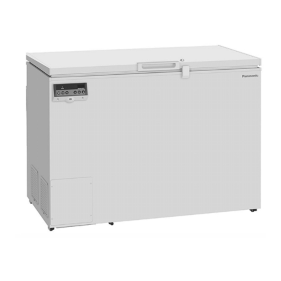
FREEZER COMPONENTS MDF-137 Power cord MDF-437... - Page 10 FREEZER COMPONENTS 1. Door: To open the door, grip the handle. 2. Handle: Always grip this handle to open and close the door. 3. Lock: Turn counterclockwise to 180 with a key and the door is securely locked. 4. Access port: This is used for leading the measuring cable from the chamber to the outside. 5.
-
Page 11: Control Panel
FREEZER COMPONENTS Control panel 1. Alarm lamp (ALARM): This lamp is flashed when unit is in alarm status. See page 18. 2. Digital temperature indicator: Normally, the current chamber temperature is displayed. In alarm status, an error code and chamber temperature is displayed alternately. See page 18. 3. -
Page 12: Installation Site
INSTALLATION SITE To operate this unit properly and to obtain maximum performance, install the unit in a location with the following conditions: A location not subjected to direct sunlight Do not install the unit under direct sunlight. Installation in a location subjected to direct sunlight cannot obtain the intended performance. -
Page 13: Installation
INSTALLATION 1. Removing the packaging materials and tapes Remove all transportation packaging materials and tapes. Open the door and ventilate the unit. If the outside panels are dirty, clean them with a diluted neutral dishwashing detergent. (Undiluted detergent can damage the plastic components. For the dilution, refer to the instruction of the detergent.) After the cleaning with the diluted detergent, always wipe it off with a wet cloth. -
Page 14: Start-Up Of Unit
START-UP OF UNIT Follow the procedures for the initial and consequent operations of the unit. 1. Turn the power switch ON with the chamber empty. 2. Turn ON the battery switch. 3. Set the chamber temperature to a desired value. 4. -
Page 15: Chamber Temperature Setting
CHAMBER TEMPERATURE SETTING Table 1 shows the basic procedure for setting the chamber temperature. Perform key operations in the sequence indicated in the table. The example in the table is based on the assumption that the desired temperature is -25 Note: The unit is set at the factory that the set temperature -30 Table 1. -
Page 16: Alarm Temperature Setting
ALARM TEMPERATURE SETTING This unit is provided with both high and low temperature alarms. The temperature at which the alarm is activated may be changed. The available set range for high temperature alarm is between +5 C and +15 C, and -5 C and -15 C for low temperature alarm against the chamber temperature. -
Page 17: Setting Of Alarm Resume Time
SETTING OF ALARM RESUME TIME The alarm buzzer is silenced by pressing alarm buzzer stop key (BUZZER) on the control panel during alarm condition. The alarm buzzer will be activated again after certain suspension if the alarm condition is continued. The suspension time can be set by following the procedure shown in the Table 5 below. The example in the table is based on the assumption that the desired duration is 20 minutes. -
Page 18: Change Of Compressor Delay Time
CHANGE OF COMPRESSOR DELAY TIME The compressor delay time can be changed to reduce the load on the power line and to facilitate the start-up (resume) of the freezer after power failure. The example in the table is based on the assumption that the delay time is changed to 4 minutes. (The delay time is set in 3 minutes at the factory.) Note: The set range for delay time is between 3 and 15 minutes. -
Page 19: Alarms & Safety Functions
ALARMS & SAFETY FUNCTIONS This unit has the alarms and safety functions and also self diagnostic functions shown in Table 7. Table 7. Alarms, safety functions and self diagnostic functions Alarm Situation Indication Buzzer Safety operation If the chamber temperature is higher Alarm lamp is flashed. -
Page 20: Routine Maintenance
ROUTINE MAINTENANCE WARNING Always disconnect the power supply to the unit prior to any repair or maintenance of the unit in order to prevent electric shock or injury. Ensure you do not inhale or consume medication or aerosols from around the unit at the time of maintenance. -
Page 21: Troubleshooting
TROUBLESHOOTING Malfunction Check/Remedy The circuit breaker of power source is active. The chamber is not cooled The voltage is too low. (In this case, call an electrician.) at all The power switch is not ON. The large amount of articles (load) is stored in the chamber at one time. -
Page 22: Disposal Of Unit
DISPOSAL OF UNIT WARNING If the unit is to be stored unused in an unsupervised area for an extended period ensure that children do not have access and door cannot be closed completely. The disposal of the unit should be accomplished by appropriate personnel. Always remove lids to prevent accidents such as suffocation. - Page 23 The symbol mark and recycling systems described below apply to EU countries and do not apply to countries in other areas of the world. Your Panasonic product is designed and manufactured with high quality materials and components which can be recycled and/or reused.
- Page 24 POUR LES UTILISATEURS DE UE Le symbole et les systèmes de recyclage évoqués ci-dessous s'appliquent uniquement aux pays de UE. Votre produit Panasonic est conçu et fabriqué avec des composants et des matériaux de hautes qualités qui peuvent être recyclés et/ou réutilisés.
- Page 25 O símbolo e os sistemas de reciclagem descritos abaixo aplicam-se aos países da UE e não se aplicam aos países noutras áreas do mundo. O seu produto Panasonic foi concebido e fabricado com materiais e componentes de elevada qualidade que podem ser reciclados e/ou reutilizados.
- Page 26 Het symbool en de recycleersystemen die hieronder beschreven worden, zijn van toepassing op de landen in de EU en zijn niet van toepassing op landen in andere delen van de wereld. Uw Panasonic product is ontworpen en gemaakt met materialen en onderdelen van hoge kwaliteit, die gerecycleerd en opnieuw gebruikt kunnen worden.
-
Page 27: Disposal Of Battery
DISPOSAL OF BATTERY Location of a nickel-metal-hydride battery This unit is provided a nickel-metal-hydride battery for the power failure alarm. The battery is located in the control box at the back of the product. (Fig. 1) The high voltage components are enclosed in the control box. The cover should be removed by a qualified engineer or a service personnel only to prevent the electric shock. -
Page 28: Temperature Recorder (Option)
TEMPERATURE RECORDER (OPTION) Installation of MTR-4015LH and MTR- G85C The chamber temperature is recorded and maintained by attaching a temperature recorder available as an optional component. For the attachment, the recorder fixing is necessary. Consult our sales representative or agent for the temperature recorder installation. Temperature recorder Recorder fixing MTR-4015LH... - Page 29 TEMPERATURE RECORDER (OPTION) 4. Place the recording paper beneath the arm and between the plate spring and guide plate in the direction of the arrow. Note: Do not scratch or put pressure on the recording paper. Do no bend the recording paper. Do not reverse the recording paper manually.
-
Page 30: Setting Of Mtr-G85C
TEMPERATURE RECORDER (OPTION) Setting of MTR-G85C Chart guides Pen cap holder Backup battery Pen arm Chart hub cover Pen lifter Recording paper Pen lifter stopper Ink pen Paper speed selector Key lock Latch Pilot lamp Fast feed button Power switch Zero adjustment screw Loading the ink pen: 1. - Page 31 TEMPERATURE RECORDER (OPTION) Starting recording and setting the time: Turn the power switch ON. The ink pen will move inward on the circular recording paper and stop temporarily at the Ink pen 0% position (equivalent to the 40 C line). Then the ink pen will move to the position which indicates the measured Hour temperature.
-
Page 32: Interface Board (Option)
INTERFACE BOARD (OPTION) The temperature log of our medical equipment can be loaded into a personal computer by using the combination of optional interface board (MTR-480) and data acquisition system (MTR-5000). For the loading, RS-232C is needed to connect our medical equipment with a personal computer. The combination of optional LAN interface board (MTR-L03) and data acquisition system (MTR-5000) enables the equipment monitoring (such as chamber temperature) by connecting our medical equipment with the data acquisition system (MTR-5000) with LAN. -
Page 33: Specifications
SPECIFICATIONS Biomedical Freezer Biomedical Freezer Biomedical Freezer Product name MDF-137 MDF-237 MDF-437 W640 mm x D687 mm x W905 mm x D687 mm x W1265 mm x D807 mm x External dimensions H881 mm H881 mm H902 mm W525 mm x D440 mm x W790 mm x D440 mm x W1140 mm x D550 mm x Internal dimensions ... -
Page 34: Performance
PERFORMANCE Biomedical Freezer Biomedical Freezer Biomedical Freezer Name MDF-137 MDF-237 MDF-437 Model number MDF-137-PE MDF-237-PE MDF-437-PE Cooling performance C (ambient temperature; 35 C, no load) Temperature control range C to -30 Rated voltage AC 220 V/230 V/240 V Rated frequency 50 Hz Rated power consumption 95 W/100 W/100 W... -
Page 35: Safety Check Sheet
CAUTION Please fill in this form before servicing. Hand over this form to the service engineer to keep for his and your safety. Safety check sheet □Yes □No 1. Freezer contents : □Yes □No Risk of infection: □Yes □No Risk of toxicity: □Yes □No Risk from radioactive sources:... - Page 36 1-1-1 Sakata, Oizumi-Machi, Ora-Gun, Gunma 370-0596, Japan Printed in Japan 7FB6P15159100 © Panasonic Healthcare Co., Ltd. 2013 S0913-0...