Table of Contents
Quick Links
Table of Contents

Related Manuals for Huawei EM820W


Summary of Contents for Huawei EM820W
- Page 1 HUAWEI EM820W HSPA+ PC Embedded Module User Guide Issue Date 2010-12-30...
- Page 2 E-mail: [email protected] Please refer color and shape to product. Huawei reserves the right to make changes or improvements to any of the products without prior notice. Copyright © Huawei Technologies Co., Ltd. 2009. All rights reserved. No part of this document may be reproduced or transmitted in any form or by any means without prior written consent of Huawei Technologies Co., Ltd.
- Page 3 HUAWEI EM820W HSPA+ PC Embedded Module User Guide About This Document About This Document History Version Date Chapter Descriptions 2010-12-30 Creation Huawei Proprietary and Confidential Issue 01 (2010-12-30) Copyright © Huawei Technologies Co., Ltd.
-
Page 4: Table Of Contents
3.4 RF Antenna Interface ........................6 .............................7 4 Usage Guide 4.1 Usage of the EM820W Simplified Board ................... 7 4.2 Test Points on the EM820W Simplified Board ................8 4.3 Material List ........................... 9 Huawei Proprietary and Confidential Issue 01 (2010-12-30) - Page 5 HUAWEI EM820W HSPA+ PC Embedded Module User Guide Tables Tables Table 4-1 Material list ......................... 9 Huawei Proprietary and Confidential Issue 01 (2010-12-30) Copyright © Huawei Technologies Co., Ltd.
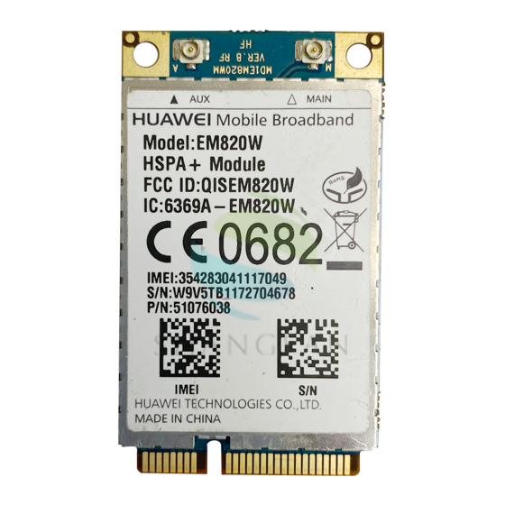
- Page 6 HUAWEI EM820W HSPA+ PC Embedded Module User Guide Figures Figures Figure 1-1 Overall appearance of an EM820W module ............... 1 Figure 2-1 Structure of the EM820W simplified board ..............2 Figure 3-1 External power interface circuit ..................4 Figure 3-2 SIM card circuit ........................
-
Page 7: Product Overview
Antenna interface It is used to connect and fix an antenna. Fixing hole A screw, metal fastener, and nut are used to fix an EM820W module on a development board through this fixing hole. PCI Express connector It is connected to the PC PCI Express connector. -
Page 8: Introduction To The Development Board
The EM820W module works inside the portable computer through the Mini PCI-E interface, which is inconvenient for the user during measurement and commission. With the EM820W simplified board, the signals that the EM820W module needs on the Mini PCI-E interface are simulated outside the portable computer. The signals are used for product development, commission, and software upgrade on production lines. - Page 9 HUAWEI EM820W HSPA+ PC Embedded Module User Guide Introduction to the Development Board On the module, the Mini-PCI interface signals are: voltage of power, SIM card interface, USB D+, D-interface, LED indicator interface. The implementation of signals on the simplified board is as follows: Voltage of power: The USB port of the PC supplies the power (5 V), which is converted into 3.3 V power for the module.
-
Page 10: Functions Of The Interfaces On The Development Board
Functions of the Interfaces on the Development Board 3.1 Power Interface The power interface is used to connect an external Mini USB Port to the EM820W module. Thus, power can be supplied to the module. Figure 3-1 shows a circuit of the external power interface. -
Page 11: Mini Pci Express Interface
Figure 3-2 SIM card circuit 3.3 Mini PCI Express Interface The interface of the EM820W is a standard Mini PCI Express interface. The EM820W consists of several major signals, as shown in the following figure. Figure 3-3 Mini PCI Express Interface USIM interface: The USIM interface provides the interface for a USIM card. -
Page 12: Rf Antenna Interface
Functions of the Interfaces on the User Guide Development Board voltage bus, USB functions implemented on EM820W which are expected to report as self-powered devices. Control signals: The auxiliary signals provide some other functions. Power sources and grounds: The PCI Express Mini Card provides a 3.3 V power source. -
Page 13: Usage Guide
Usage Guide Usage Guide 4.1 Usage of the EM820W Simplified Board Connect the devices as follows to establish the test environment: Connect one end of the module to the Mini PCI-E connector, and lock the other end to the locker. Insert the SIM card into the card holder, and connect the PC and the board with the USB cable as shown in the Figure 4-1. -
Page 14: Test Points On The Em820W Simplified Board
(For the connection method, see Figure 4-2) 4.2 Test Points on the EM820W Simplified Board On the EM820W simplified board, some important signals related to the module on the Mini-PIC-E interface are the test points, as shown in Figure 4-3. -
Page 15: Material List
HUAWEI EM820W HSPA+ PC Embedded Module User Guide Usage Guide TS201: WAKE_NB_N, which is the signal that the module wakes up the host. TS219: W_DISABLE_N, which is the signal that enable/disable the RF. TS227: LED_WWAN, which is the signal that indicates the network card status.