Siemens 3AH3 Instruction Manual
Vacuum circuit breaker operator modules 4.16 kv to 38 kv
Hide thumbs
Also See for 3AH3:
- Operating instructions manual (27 pages) ,
- Operating instructions manual (64 pages)

Related Manuals for Siemens 3AH3


Summary of Contents for Siemens 3AH3
- Page 1 Instruction manual Types 3AH3 and 3AHc vacuum circuit breaker operator modules 4.16 kV to 38 kV Installation operation maintenance E50001-F710-A251-V1-4A00 Answers for infrastructure and cities.
- Page 2 Such persons are permitted maintenance of the equipment purchased. to work within limited approach of exposed Siemens reserves the right to make changes live parts operating at 50 volts or more, and in the specifications shown herein or to...
-
Page 3: Table Of Contents
The sales contract contains the entire obligation of Siemens Industry, Inc. The warranty contained in the contract between the parties is the sole warranty of Siemens Industry, Inc. Any statements contained herein do not create new warranties or modify the... -
Page 4: Introduction
Caution (without safety alert symbol) - Indicates a potentially hazardous situation In this instruction manual, reference to type that, if not avoided, may result in property 3AH includes both type 3AH3 and type 3AHc damage. operator modules. When information specific to the type 3AH-compact (3AHc) - Page 5 Contact control power removed before regional service centers, sales offices or the performing any tests, maintenance or factory for details, or telephone Siemens repair. field service at 1-800-347-6659 or 1-919- 2. Always perform maintenance on the 365-2200 outside the U.S.
-
Page 6: Receiving, Handling And Storage
Important: The manner in which visible covers the receiving, handling and storage shipping damage is identified by consignee instructions for a type 3AH3 vacuum circuit prior to signing the delivery receipt can breaker operator module. This section of the determine the outcome of any damage instruction manual is intended to help the claim to be filed. - Page 7 365-2200 outside the U.S. their agent, Siemens cannot be held liable 5. Arrange for a carrier inspection of the for repairs. Siemens will not be held liable damage immediately. for repairs in any case where repair work was performed prior to authorization from Important: Do not move the equipment Siemens.
- Page 8 Storage procedure 1. Whenever possible, install the circuit breaker operator module in its assigned switchgear enclosure or end location for storage. 2. When the circuit breaker operator module needs to be placed on its pallet for storage, be sure the unit is securely bolted to the pallet and covered with polyethylene film at least 10 mils thick.
-
Page 9: Installation Checks And Functional Tests
Installation checks and functional tests Hazardous voltage and high-speed moving parts. Will cause death, serious injury and property damage. Read instruction manuals, observe safety instructions and use qualified personnel. Introduction De-energizing control power in This section provides a description of the switchgear inspections, checks and tests to be When the circuit breaker is mounted in... - Page 10 Spring-discharge check (refer to Figure 1) Automatic spring-charging check Perform the spring-discharge check before The automatic spring-charging features of removing the circuit breaker or operator the circuit breaker must be checked. Control module from the pallet or removing it from power is required for automatic spring- the switchgear.
-
Page 11: Vacuum Interrupter/Operator
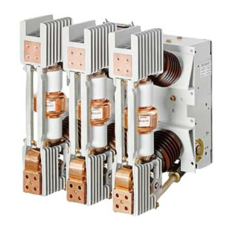
Vacuum interrupter/ operator Figure 2: Vacuum circuit breaker operator module 3AH vacuum circuit breaker operator 3AHc vacuum circuit breaker operator Item Description Item Description Pole head Guide link Upper connection pad Upper post insulator Introduction Strut Operator housing The type 3AH vacuum circuit-breaker Vacuum interrupter Lower post insulator operator is intended for application in a... - Page 12 Figure 3 is a section view of a typical vacuum interrupter. The entire assembly is sealed after a vacuum is established. 3AH3 operator mechanism The vacuum interrupter stationary contact is 3AH vacuum circuit breaker operator connected to the upper pole head of the circuit breaker.
- Page 13 Phase barriers (if applicable) The energy-storing mechanism and all the Plates of glass-polyester insulating material control and actuating devices are installed are attached to the circuit breaker and in the operator housing. The mechanism is provide suitable electrical insulation of the spring stored-energy type and is between the vacuum interrupter and mechanically and electrically trip-free.
- Page 14 During closing, the opening spring (64.0) Motor-operating mechanism (refer to (refer to Figure 6) and the contact pressure Figure 5) springs (49.0) are charged and latched by The spring-charging motor (50.4) is bolted pawl (64.2) (refer to Figure 6). The closing to the charging mechanism (50.2) gear box spring (62.0) (refer to Figure 5) of the installed in the operator housing.
- Page 15 Figure 5: Stored-energy operating mechanism (circuit breaker shown in OPEN position) (straight linkage shown) 62.5 55.2 62.3 50.3 62.1 62.5.2 62.2 68.0 53.0 50.5 62.6 50.2 55.1 53.1 62.0 54.1 50.4.1 54.0 55.0 50.4 64.0 68.1 58.0 63.0 63.1 63.5 61.8 59.0 60.0...
- Page 16 Item Description Closing (refer to Figures 5, 7-10) If the circuit breaker is to be closed 54.0 Open pushbutton manually, the closing spring is released by 62.8.1 62.8 Trip-free coupling rod pressing the Close button (53.0). In the case 62.8.1 Spring-return latch of remote electrical control, the close coil Trip-free coupling link...
- Page 17 Trip-free coupling link (62.8.2) and trip-free Manual operation coupling lever (62.8.3) cause the spring- Electrically operated vacuum circuit breakers return latch position to be dependent upon can be operated manually if the control the normal tripping components and the supply should fail. racking interlock (if applicable).
- Page 18 Figure 7: Operating mechanism section diagram (drawout trip-free linkage shown) mechanism OPEN, closing spring DISCHARGED Item Description 48.0 Insulating coupler 50.3 Charging flange 50.3.1 Driver 53.0 Close pushbutton 62.5.1† 62.5 53.1 Close coil 52SRC 62.1 54.0 Open pushbutton 62.3† 50.3 54.1 Trip coil 52T 62.2†...
- Page 19 Figure 8: Operating mechanism section diagram (drawout trip-free linkage shown) mechanism OPEN, closing spring DISCHARGED Item Description 48.0 Insulating coupler 50.3 Charging flange 50.3.1 Driver 53.0 Close pushbutton 53.1 Close coil 52SRC 62.2† 54.0 Open pushbutton 50.3.1† 54.1 Trip coil 52T 62.1†...
- Page 20 Figure 9: Operating mechanism section diagram (drawout trip-free linkage shown) mechanism CLOSED, closing spring DISCHARGED Item Description 48.0 Insulating coupler 53.0 Close pushbutton 53.1 Close coil 52SRC 62.1 Charging shaft 62.2 Crank 62.2.2 Closing-spring mounting 62.3 Cam disc 62.5 Lever 62.5.1 62.5.1 Pawl roller...
- Page 21 Figure 10: Operating mechanism section diagram (drawout trip-free linkage shown) mechanism CLOSED, closing spring CHARGED Item Description 50.3 Charging flange 50.3.1 Driver 62.1 Charging shaft 62.2 Crank 62.2.2 Closing-spring mounting 62.3 Cam disc 62.5 Lever 62.5.1 Pawl roller 62.2 50.3.1 62.3 62.1 62.5...
- Page 22 Figure 11: Operator sequential operation diagram Closing Closed voltage applied. Anti-pumping feature (52Y) assures a continuously applied closing command does not cause the circuit breaker to reclose automatically after it has tripped out on a fault. Spring-charge motor Undervoltage device Continuous (88.0) energized.
- Page 23 The schematic shown in Figure 14 is intended to aid in understanding the 50.0 mechanism operation discussed in this 50.5 53.0 instruction manual. It shows a drawout circuit breaker as an example. Refer to the schematic diagram furnished with your circuit breaker for specific information.
- Page 24 Figure 14: Typical elementary diagram SD16 SD13 LS21 Motor LS41 DC supply LS22 52SRC SD14 SD15 SD11 SD12 SD10 Standard: Fuses in close circuit. Slugs in trip circuit (fuses optional). Shown with springs discharged, trip-latch reset, circuit breaker open, connect or withdrawn position. Item Description Item...
- Page 25 Indirect releases - secondary shunt release (dual trip) (52T1) or undervoltage (27.0) 33.0 The indirect release provides for the 23.0 conversion of modest control signals into 31.0 27.0 25.0 powerful mechanical-energy impulses. It is 21.0 primarily used to open medium-voltage 11.0 13.0 circuit breakers while functioning as a...
- Page 26 Construction and mode of operation of secondary shunt-release and Position A: locked (disabled) undervoltage release (refer to Figures 15, 16 and 17) The release consists of a spring-power stored-energy mechanism, a latching device 29.0 and an electromagnet. 23.0 These elements are accommodated side by side in a housing (3.0), with a detachable cover and three through-holes (5.0) for fastening screws.
- Page 27 Since the striker pin of the undervoltage Shock absorber release 3AX1103 is latched only when the Circuit breakers are equipped with a armature is energized, the undervoltage hydraulic shock absorber (61.8) (refer to release is provided with a screw (29.0), for Figure 5).
-
Page 28: Maintenance
Introduction and maintenance intervals Regardless of the length of the maintenance Periodic inspections and maintenance are and lubrication interval, Siemens essential to safe and reliable operation of recommends that circuit breakers should be the circuit breaker operator module. inspected and exercised annually. - Page 29 User’s purposes, the matter should be referred to the local Open-end wrench: 55 mm used to Siemens sales office. exchange shock absorber (Quantity: two pieces are required for the task) Checks of the primary power path...
- Page 30 The use of unauthorized parts in the repair of the equipment, or tampering by unqualified personnel can result in hazardous conditions, that can result in death, serious injury or property damage. Follow all safety instructions contained herein. Inspection items and tests Cleanliness check Figure 2 is a side view of the circuit breaker Primary-power path checks...
- Page 31 Maintenance and lubrication Lubricants composed of ester oils and Table 2 gives the recommended lithium thickeners will generally be maintenance intervals for circuit breakers. compatible. These intervals assume that the circuit For all lubrication (except electrical breaker is operated under “usual service moving or sliding surfaces), use one of conditions”...
- Page 32 Figure 19: Operator mechanism lubrication Klüber L32 or Klüber L32N Typical for all three-phases...
- Page 33 High-speed moving parts. Can result in serious injury. Tripping spring is charged. If trip latch is moved, the stored-energy springs will discharge rapidly. Stay clear of circuit breaker components that are subject to sudden, high- speed movement. The contact-erosion check procedure is: a) Be sure the circuit breaker primary contacts are CLOSED.
- Page 34 Hazardous voltage and high-speed moving parts. Will cause death, serious injury and property damage. De-energize before working on this equipment. Read instruction manuals, observe safety instructions and use qualified personnel. Check of the wiring and terminals Electrical close and trip check (control 1.
- Page 35 Table 3: Typical vacuum interrupter contact life expectancy Right hand limit Rated maximum Interrupting class Vacuum Rated short-circuit current Graph of curve (refer to voltage kV interrupter type Figure 21) VS-17006 4.76 29 kA @ 4.76 kV; 36 kA @ 3.85 kV VS-17040 4.76 41 kA @ 4.76 kV;...
- Page 36 Figure 21: Typical vacuum interrupter contact life curves Load graph "A" vacuum interrupter type VS-17006 Load graph "C" vacuum interrupter type VS-25008 Load graph "E" vacuum interrupter type VS-17040 Permissible operating cycles 100,000 50,000 20,000 10,000 5,000 2,000 1,000 31.5 Breaking current (symmetrical value) Note: Right-hand vertical segment of curve is located at the maximum symmetrical interrupting current rating of the circuit breaker, as indicated in...
- Page 37 Figure 21: Typical vacuum interrupter contact life curves (continued) Load graph "B" vacuum interrupter type VS-15052 Load graph "D" vacuum interrupter types VS-30030 and VS-30041 Load graph "F" vacuum interrupter type VS-17085 Permissible operating cycles 100,000 50,000 20,000 10,000 5,000 2,000 1,000 Breaking current (symmetrical value)
- Page 38 Checks of the spring-charging motor Vacuum-integrity check (using (88.0) mechanical test) (refer to Figure 22) No additional checks of the spring-charging Before putting the circuit breaker into motor are necessary. If it is necessary to service, or if a vacuum interrupter is remove or replace the spring-charging suspected of leaking as a result of motor, torque motor-mounting hardware to...
- Page 39 Vacuum interrupters may emit X-ray radiation. Can result in serious injury. Keep personnel more than six feet away from a circuit breaker under test. High-potential tests High-potential test voltages The next series of tests (vacuum-integrity The voltages for high-potential tests are test and insulation tests) involve use of shown in Table 4.
- Page 40 Item Description 48.0 Insulating coupler 48.6 Lever Detach lever (48.6) and insulated Step 1 coupler (48.0) 48.0 Primary contact CLOSED position and Step 2 Step 2 insulated coupler disconnected 48.6 48.0 Primary contact OPEN position (forced Step 3 Operating open by manual pressure) 48.0 48.6 position...
- Page 41 Insulation and contact-resistance test Inspection and cleaning of circuit breaker Contact Current rating resistance procedure insulation Micro-Ohms 1. Observe safety precaution listed in the 1. Perform the spring-discharge check danger and warning advisories for the (refer to page 9) on the circuit breaker 1,200 vacuum integrity check tests (refer to after all control power is removed.
-
Page 42: Overhaul
Replacement of vacuum interrupters Vacuum interrupters as determined by It is recommended that vacuum interrupters vacuum integrity test, contact erosion or be replaced only by a qualified Siemens field according to overhaul schedule (refer to service representative. The information in Table 6) the following sections is provided to aid in understanding the replacement procedures. - Page 43 These extension, loosen and remove hex-cap interrupters must be replaced by factory- screw fastening the pole head to the trained personnel. Contact Siemens post insulator. Completely remove the medium-voltage customer service at 1-800- pole head and set aside.
- Page 44 Figure 23: Vacuum interrupter replacement illustration - type 3AH Item Description 20.0 Upper pole-support (pole head) 28.0 Strut 28.1 Centering ring 20.0 29.1 Flexible connector 31.2 29.2 Terminal clamp 29.3 Spacer (or shoulder) 30.0 Vacuum interrupter 31.2 Upper terminal bolt 36.1 Moving terminal 36.3...
- Page 45 Figure 24: Illustration showing required technique for fastening terminal-clamp hardware Item Description Moving contact (36.1) Spacer (shoulder) (29.3) Torque wrench Direction of force (P) Terminal clamp (29.2) Holding wrench Vacuum interrupter Position of torque wrench to avoid undue stressing of moving contact (36.1) 2.5 Attach struts (28.0) to the upper pole- 2.7 Raise the terminal clamp (29.2) against support (20.0), replace hardware...
- Page 46 2.8 Align pole head (20.0) correctly and 3.5 Repeat the measurement described in tighten bolt fastening it to the post step 3.3 again with care to maximize insulator. Torque M16 bolt to 130 Nm accuracy. Record your result. (96 ft-lb). Fasten securely all bolts 3.6 Determine difference between the associated with struts (28.0).
-
Page 47: Technical Data And Troubleshooting
33 [email protected] kV; If you need assistance achieving 8.25 VS-15052 1,200, 2,000, 3,000 8.5-9.5 41 [email protected] kV the indicated stroke setting, con- tact the nearest Siemens 18 [email protected] kV; 15.0 VS-17006 1,200, 2,000 representative. 23 [email protected] kV 28 [email protected] kV;... - Page 48 5. Motor cut-off switch LS21 or LS22 fails to operate. Replace if necessary. 6. Mechanical failure of operating mechanism. Check and contact the factory or Siemens field service at 1-800-347-6659 or 1-919-365-2200 outside the U.S. 1. Secondary control circuit de-energized or control circuit fuses blown.
- Page 49 Check and replace if required. not open. In other words, they remain closed. 1. Mechanical failure of operating mechanism. Check and contact the factory or Siemens Tripping coil (52T) energizes. Tripping sound is field service at 1-800-347-6659 or 1-919- heard, but circuit breaker contacts do not 365-2200 outside the U.S.
- Page 50 Table 9: Circuit breaker control data ANSI/IEEE C37.06 control voltages Spring charging motor Close Trip coil Inrush coil Range Charging (Average) (Peak) Nominal Close Trip Seconds 24 Vdc 19-28 14-28 15/---- ---- ---- ---- 48 Vdc 36-56 28-56 11.4 11.4/30 125 Vdc 100-140 70-140...
- Page 51 Table 11: Type 3AH vacuum circuit breaker ratings (new "constant kA" ratings basis) Maximum These ratings are in Withstand voltage Continuous Short-circuit design accordance with: levels current Voltage voltage (V) Circuit breaker range ANSI/IEEE C37.04-1999 Lightning type factor Power Standard Rating Structure impulse kV rms frequency...
- Page 52 Table 11: Type 3AH vacuum circuit breaker ratings (new "constant kA" ratings basis) (continued) Permissible Interrupting Max. sym. % dc Short-time tripping delay Closing and latching (momentary) time interrupting (I) component current (I) (3 s) Circuit breaker type Asymmetrical Peak ms/cycles kA rms sym kA rms...
- Page 53 Table 12:Type 3AH vacuum circuit breaker ratings (historic "constant MVA" ratings basis) These ratings are in Nominal Maximum Voltage accordance with: Nominal three- design Continuous range Withstand voltage voltage phase ANSI/IEEE C37.04-1979 voltage current factor levels class Standard Rating Structure Circuit class breaker type...
- Page 54 Table 12:Type 3AH vacuum circuit breaker ratings (historic "constant MVA" ratings basis) (continued) Short-circuit Rated (at rated maximum Maximum Short-time Permissible maximum Interrupting design symmetrical current (I) Closing and latching tripping delay design time voltage (V) interrupting (three (momentary) voltage) divided by K (K x I) seconds)
- Page 55 Table 13: Type 3AH3 vacuum circuit breaker weight in lbs (kg) (circuit breaker operator only) Footnote: Circuit breaker type Weight in lbs (kg) Add 100 lbs (45 kg) for packaging. Interrupting Continuous current For weights of circuit breakers Maximum voltage...
- Page 56 All product designations may be trademarks or product names of Siemens AG or supplier companies whose use by third parties for their own purposes could violate the rights of the owners.