Table of Contents
Quick Links
INSTALLATION & OPERATION
A53689 AIRLINK VENUS
SOFTWARE DEFINED RADIO (SDR)
OCTOBER 2021
DOCUMENT NO. COM-00-21-04
VERSION A.1
Siemens Mobility, Inc.
One Penn Plaza
Suite 1100
New York, NY 10119-1101
1-800-793-SAFE
www.usa.siemens.com/rail-manuals
Copyright © 2021 Siemens Mobility, Inc.
All Rights Reserved
PRINTED IN U.S.A.
Table of Contents

Related Manuals for Siemens AIRLINK VENUS


Summary of Contents for Siemens AIRLINK VENUS
- Page 1 A53689 AIRLINK VENUS SOFTWARE DEFINED RADIO (SDR) OCTOBER 2021 DOCUMENT NO. COM-00-21-04 VERSION A.1 Siemens Mobility, Inc. One Penn Plaza Suite 1100 New York, NY 10119-1101 1-800-793-SAFE www.usa.siemens.com/rail-manuals Copyright © 2021 Siemens Mobility, Inc. All Rights Reserved PRINTED IN U.S.A.
-
Page 2: Proprietary Information
English. Any translation of the manuals and product information is unofficial and can be imprecise and inaccurate in whole or in part. Siemens Mobility, Inc. does not warrant the accuracy, reliability, or timeliness of any information contained in any translation of... -
Page 3: Fcc Rules Compliance
Connect the equipment into an outlet on a circuit different from that to which the receiver is connected. • Consult Siemens Customer Service for help. Modifications not expressly approved by the manufacturer could void the user's authority to operate the equipment under FCC rules. -
Page 4: Human Exposure Statement
HUMAN EXPOSURE STATEMENT This equipment is designed to generate and radiate radio frequency (RF) energy using an external antenna. When terminated into a non-radiating RF load, the radio is certified to comply with FCC regulations pertaining to human exposure to RF radiation in accordance with the FCC Rules Part 1 section 1.1310 as published in title 47 code of federal regulations and procedures established in TIA/EIA TSB92, Report On EME Evaluation for RF Cabinet Emissions Under FCC MPE Guidelines. -
Page 5: General Safety Precautions
GENERAL SAFETY PRECAUTIONS Safety precautions must be observed at all times during all phases of installation, operation, service, and repair of the equipment described in this manual. The following precautions are warnings to be aware of. These warnings and precautions are necessary for the safe operation of the equipment. -
Page 6: Document History
DOCUMENT HISTORY Version Release Sections Details of Change Date Changed 10-05-2021 Initial Release 10-26-2021 Pg 1-3 Section 1.1 Specifications, changed power consumption peak from 23.4 watts to 48 watts (2 Amps) Updated Glossary, Pg 1-3, Section 1.1 Add Title to compliance standard Pg 1-4 Section 1.2 Add FCC Certification ID COM-00-21-04... -
Page 7: Table Of Contents
TABLE OF CONTENTS Section Title Page PROPRIETARY INFORMATION ......................ii TRANSLATIONS ............................. ii WARRANTY INFORMATION ........................ii SALES AND SERVICE LOCATIONS ....................... ii FCC RULES COMPLIANCE ........................iii HUMAN EXPOSURE STATEMENT......................iv GENERAL SAFETY PRECAUTIONS ...................... v MANUAL SCOPE ............................ v DOCUMENT HISTORY .......................... - Page 8 WinSCP ........................5-5 5.2.7 Startup Dialog ......................5-5 5.2.8 Base Station ......................5-6 5.2.8.1 Base Station Remote Access .................. 5-6 5.2.8.1.1 BS50000 File Structure ..................5-6 5.2.9 WinSCP Configuration of Airlink Venus..............5-8 viii COM-00-21-04 OCTOBER 2021 Version No.: A.1...
- Page 9 Remote Radio Station ................... 5-10 5.2.12 Remote Radio Configuration Overview ..............5-11 5.2.12.1.1 Cobalt Remote Software Configuration for the Airlink Venus Radio ....5-11 Maintaining Multiple Configuration File Versions ..............5-13 Coordinated Configuration File Changes ................5-14 OPERATION ..........................6-1 Description ..........................
-
Page 10: List Of Figures
Figure 2-2 Venus Radio Components ....................2-2 Figure 2-3 Airlink Venus Radio Dimensions ..................2-3 Figure 2-4 Airlink Venus Radio Modular Board Design ................ 2-4 Figure 2-5 RF and IF SAW Filter Block Diagram ................. 2-6 Figure 3-1 Wall Mount Example ......................3-3 Figure 3-2 Mounting Dimensions –... - Page 11 LIST OF TABLES Section Title Page Table 1-1 Airlink Venus Part Numbers ....................1-4 Table 3-1 Connection Summary ......................3-11 Table 4-1 Troubleshooting Matrix ......................4-1 Table 5-1 Console Configuration ......................5-3 Table 5-2 Base Station Configuration Overview .................. 5-9 Table 5-3 Remote Station Configuration Overview ................
-
Page 12: Notes, Cautions, And Warnings
EQUIPMENT. CAUTIONS TAKE PRECEDENCE OVER NOTES AND ALL OTHER INFORMATION, EXCEPT WARNINGS. NOTE Generally used to highlight certain information relating to the topic under discussion. If there are any questions, contact Siemens Mobility, Inc. Application Engineering. COM-00-21-04 OCTOBER 2021 Version No.: A.1... -
Page 13: Electrostatic Discharge (Esd) Precautions
(ESD) during the handling, shipping, and storage of electronic modules and components. Siemens Industry, Inc. has instituted these practices at its manufacturing facility and encourages its customers to adopt them as well to lessen the likelihood of equipment damage in the field due to ESD. -
Page 14: Glossary
GLOSSARY TERM DESCRIPTION Association of American Railroads - An organization that establishes uniformity and standardization among different railroad systems. Advanced Encryption Standard Branch is Less or Equal Base Station Communications Base Board Command Line Interface decibel milliwatts A DIN rail is a metal rail of a standard type widely used for mounting circuit breakers and industrial control equipment inside equipment racks. - Page 15 TERM DESCRIPTION Intermediate Frequency Internet Protocol - ISO Model Layer 3 (network) protocol that performs proper routing of packets. Intermediate & Radio Frequency Module Local Area Network - A limited network where the data transfer medium is generally wires or cable. Light Emitting Diode NEMA National Electrical Manufacturers Association...
- Page 16 TERM DESCRIPTION Surface Acoustic Wave SCADA Supervisory Control and Data Acquisition Software Defined Radio Sub-Miniature version A SNMP Simple Network Management Protocol Secure Shell Software Time Division Duplexing Transmit ULSF Up Link Sub Frame COM-00-21-04 OCTOBER 2021 Version No.: A.1...
-
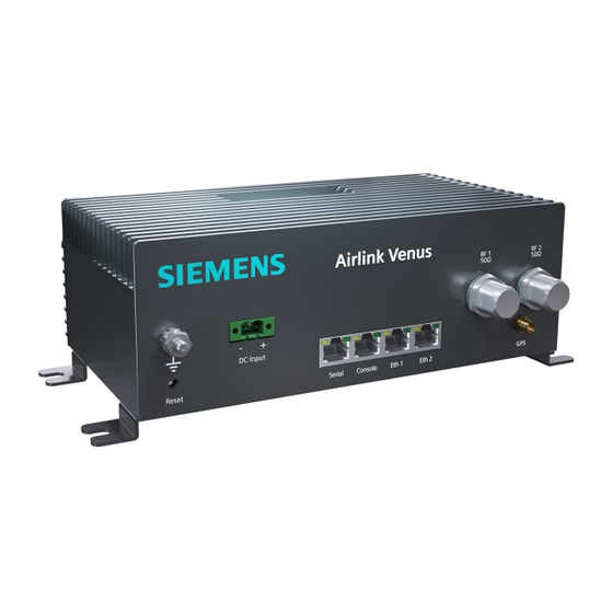
Page 17: Product Description
Figure 1-1 A53689 Airlink Venus Radio The Airlink radio network can be made up of Airlink Venus radios or used in conjunction with Siemens’ other hardware platforms to build a multi-cell, point-to-multipoint (PtMP) networks using IEEE 802.16 –... -
Page 18: Specifications
PRODUCT DESCRIPTION _________________________________________________________________________________________________________ Specifications RADIO SPECIFICATIONS Frequency Range 70 MHz to 6 GHz Channel Sizes 12.5 kHz to 10 MHz Throughput Up to 10 Mbps TX Power 36 dBm @ Antenna Port RX Sensitivity As low as -117 dBm OFDMA Waveform (orthogonal frequency-division multiple access) Modulation... - Page 19 PRODUCT DESCRIPTION _________________________________________________________________________________________________________ Specifications (continued) PHYSICAL CHARACTERISTICS 50Ω RF Antenna (2X) Active 5 VDC Input Voltage 18 to 60 VDC Data Interface 100 Base T, RS-232 No Load: 13.1 watts @ 24 VDC Power Consumption Peak Load: 48 watts (2 Amps) @ 24 VDC Indicators LCD Panel, Power LED 9.9”...
-
Page 20: Ordering Information
PRODUCT DESCRIPTION _________________________________________________________________________________________________________ Ordering Information Table 1-1 lists the ordering information for the Airlink Venus equipment. Table 1-1 Airlink Venus Part Numbers Part Number Description FCC Certificate ID 9000-53689-00 XX Base Station 160 MHZ FCC Certification Pending Base Station 217/218 MHZ... -
Page 21: Introduction
SECTION 2 INTRODUCTION INTRODUCTION Siemens’ system of frequency agnostic (software-defined) wireless base stations, fixed and mobile remote radios are based on IEEE 802.16s (the standard for broadband, wireless, fixed/mobile access systems) that enables wide-area, Internet Protocol connectivity. This allows railroads to transition from multiple, single-purpose networks to a common, managed, multi- purpose/multi-band network and realize a significant reduction of infrastructure and operating costs. -
Page 22: Summary Of Operating Features
INTRODUCTION _________________________________________________________________________________________________________ Summary of Operating Features Figure 2-2 Venus Radio Components ● Lightweight, compact, fan-less design for rugged environments ● Software Defined Radio (SDR) platform for future flexibility and new radio requirements ● Capable of Base Station and fixed or mobile remote operation ●... -
Page 23: Mechanical Design
_________________________________________________________________________________________________________ Mechanical Design The Airlink Venus radio is housed in a compact enclosure that can be wall-mounted using screws. Its enclosure is designed for rugged environments such as electrical substation control houses or switch cabinets, rail bungalows, trains, pump-off controller enclosures, or other SCADA or industrial enclosures. -
Page 24: Electrical Design
INTRODUCTION _________________________________________________________________________________________________________ Electrical Design The Airlink Venus radio is made up of modular boards as shown in the following figure. Figure 2-4 Airlink Venus Radio Modular Board Design Power Supply Unit (PSU) The PSU requires an input voltage of 18 – 60 VDC capable of supplying a minimum of 5 amps. -
Page 25: Intermediate And Radio Frequency Module (Irf)
(FFR). 2.4.4 Filtering Architecture The Airlink Venus radio is designed to operate over a wide range of frequencies and channel configurations while minimizing interference. The Airlink Venus radio can operate from 70 MHz to 6 GHz using channel sizes from 12.5 kHz to 10 MHz. With Quadrature Phase Shift Keying (QPSK) using a convolution turbo coding (CTC) rate of ½, the receiver sensitivity ranges from -... -
Page 26: Figure 2-5 Rf And If Saw Filter Block Diagram
INTRODUCTION _________________________________________________________________________________________________________ The Airlink Venus radio incorporates filtering at the following stages: ● RFM/IRF ○ RF (Image) Filter which is centered at the RF frequency of operation ○ Intermediate Frequency (IF) Filter which is centered at the IF frequency of operation ●... -
Page 27: Security Architecture Authentication And Authorization
INTRODUCTION _________________________________________________________________________________________________________ Security Architecture Authentication and Authorization Authentication is the act of verifying the user is who they claim to be. Authorization is the process of giving the user permission to access a specific resource or function. Both functions are handled by the Authentication, Authorization, and Accounting (AAA) server using multi- factor authentication. -
Page 28: Encryption
INTRODUCTION _________________________________________________________________________________________________________ The Airlink base stations and remote stations support remote digital certification revocation, renewal, and change using the Apollo toolkit as an operation that is enabled to the administrator only. Airlink currently uses a single default username and password for all base stations and remote stations. -
Page 29: Installation Overview
This information is intended to serve as an overview for installing the Airlink Venus radio and its associated equipment. Instructions for each task are provided in the following sections. -
Page 30: Environmental Considerations
3.1.4 Input Power Requirements The Airlink Venus radio requires an 18 to 60 VDC power input. The DC source must be capable of supplying 2 amps and should be on a dedicated circuit protected with a fuse or circuit breaker rated at 5 amps. -
Page 31: Equipment Installation
Figure 3-1 Wall Mount Example 3.2.3 Radio Grounding Guidelines The Airlink Venus Radio is equipped with a single ground lug located on the front of the radio. The ground post must be connected to earth ground. Install at least a 12 AWG protective ground wire with #10 size ring terminal to a safe grounding position. -
Page 32: Mechanical Installation
Mounting brackets are provided for attaching the Airlink Venus enclosure to a vertical flat surface. Note that Airlink Venus has a passive cooling system and as such, the external cooling fins should not be blocked. Provide adequate airflow around the radio enclosure, maintaining a minimum 2”... -
Page 33: Electrical Connection
3.4.1 DC Power Supply Connection The Airlink Venus radio is supplied with a mating screw terminal plug, Phoenix P/N: 1777989, this plug will accept up to 12 AWG wires from an 18 to 60 VDC power supply. The DC source must be capable of supplying 2 amps and is recommended to be on a dedicated circuit that is protected by a fuse or circuit breaker capable of 5 amps. -
Page 34: Figure 3-4 Electrical Connections
INSTALLATION _________________________________________________________________________________________________________ The electrical connections consist of a LED/Reset switch combination, a two-position terminal socket, and a grounding post on the front panel as shown in Figure 3-4. ● For PERMANENTLY CONNECTED EQUIPMENT, a readily accessible power disconnect device should be incorporated external to the equipment. ●... -
Page 35: Antenna System Connections
GPS Synchronization 3.5.1 Overview Airlink Venus employs optional GPS-based timing to synchronize the operation of the network if necessary. An optional L1 GPS antenna such as the Trimble Bullet III antenna or equivalent as noted in the following section can be ordered. When used, GPS information can be retrieved by the Command Line Interface (CLI) or SNMP interface. -
Page 36: Gps System
INSTALLATION _________________________________________________________________________________________________________ 3.5.2 GPS System The GPS consists of an Airlink Venus internal GPS module connected to an external active GPS antenna connected to the female GPS antenna port. Figure 3-6 GPS Antenna System 3.5.3 Internal GPS Module The internal GPS module includes an oscillator that may be synchronized by the GPS satellite network via the external active (+5V) antenna. -
Page 37: Gps Antenna
_________________________________________________________________________________________________________ 3.5.4 GPS Antenna The optional antenna recommended for use with the Airlink Venus is a Trimble Bullet III GPS antenna (or equivalent) as shown in Figure 3-7. This antenna requires 5 VDC which is supplied through the Airlink Venus GPS connector. -
Page 38: System Cable Connections
INSTALLATION _________________________________________________________________________________________________________ 3.5.5 System Cable Connections Depending on the type of system the Airlink Venus radio is connected to, various connections will be needed. ● Serial - RJ45 8-pin socket wired using the Cisco interface specification for RS232 serial data. -
Page 39: Connection Summary
RF1 50 Ω connector to 15 inch-pounds with 5/8” open-end wrench. Never energize the Airlink Venus radio without a 50 Ohm (4 Watt min) load (or antenna) on the RF connector. 50Ω N-Type female connector for RF input/output from the antenna. Torque hex RF2 50 Ω... -
Page 40: Special Installations
INSTALLATION _________________________________________________________________________________________________________ Special Installations NOTE A small flat blade screwdriver will be needed for the removal of RJ-45 connectors if the RJ-45 tab is cut Figure 3-9 RJ-45 Tab Cut Mandatory product labels can be found on the side of the unit as shown in Figure 3-10 Figure 3-10 Mandatory Product Labels 3-12 COM-00-21-04... -
Page 41: Post Installation Checklist
3.7.1 Applying Power Before applying power to the station, make sure all cables are securely connected. Turn ON the DC circuit breaker or install the fuse that is supplying power to the Airlink Venus radio. 3.7.2 Verifying Proper Operation When the station is starting up, initially there will be this message on the screen: While this screen appears, the radio is going through its startup menu and launching the configuration file. - Page 42 INSTALLATION _________________________________________________________________________________________________________ If the base station does not start properly, the original screen will stay up, and no other screens will scroll on the LED screen: If the remote radio does not find a base station in range to connect to or is not configured properly, the following screen will appear on the remote station’s LED screen: 3-14 COM-00-21-04...
-
Page 43: Troubleshooting
TROUBLESHOOTING _________________________________________________________________________________________________________ SECTION 4 TROUBLESHOOTING TROUBLESHOOTING If properly configured, the Remote Station (RS) and the Base Station (BS) should connect within one minute after being turned on. If the connection is not established, then the following needs to be investigated. Table 4-1 Troubleshooting Matrix PROBLEM TROUBLESHOOTING PROCEDURE... - Page 44 TROUBLESHOOTING _________________________________________________________________________________________________________ PROBLEM TROUBLESHOOTING PROCEDURE If the BS is detected (DL ACQUIRED) but a connection is not established, then the following needs to be determined: An RF scan using Apollo should be performed to verify that there is no interference in the channel. This needs to be performed at both the RS site and the BS site.
-
Page 45: Configuration
(e.g. provisioning and Quality of Service), certain elements are preconfigured in the remote radio. There are two recommended methods of changing the configuration of the Airlink Venus radios: ● Apollo (preferred) – Siemens’ Graphic User Interface (GUI) – Information on this is provided in a separate manual ●... -
Page 46: Remote Access
WinSCP over an Ethernet connection as described in the following sections. 5.2.1 Radio Control Access Console access to Airlink Venus radios is provided by the RJ45 8 pin Console port using a Cisco standard console (USB to RJ45) cable as shown in Figure 5-1. -
Page 47: Default Passwords And Change
CONFIGURATION _________________________________________________________________________________________________________ The Console interface may be accessed using a serial application (Putty, HyperTerminal, minicom, MobaXterm, etc.) configured with the following characteristics: Table 5-1 Console Configuration Parameter Value Speed 115,200 Data Bits Stop Bits Parity None Flow Control None NOTE The console interface is also used for status reporting which can make CLI use a challenge. -
Page 48: Base Station
CONFIGURATION _________________________________________________________________________________________________________ 5.2.3 Base Station Console access to a base station radio is password protected. The username “operator” is limited to performance commands without access to configuration commands, “admin” is limited to the CLI performance AND configuration commands, while “root” provides unrestricted use. 5.2.4 Remote Station Console access to a remote radio is password protected. -
Page 49: Winscp
CONFIGURATION _________________________________________________________________________________________________________ More advanced users familiar with the Linux Operating System will find a subset of standard commands, some with limited functionality that may be used for system navigation and file manipulation in the online application partition. The open-source tool WinSCP as described in the following section may provide a more familiar environment for Windows users. -
Page 50: Base Station
CONFIGURATION _________________________________________________________________________________________________________ Figure 5-3 Entering Password 5.2.8 Base Station 5.2.8.1 Base Station Remote Access 5.2.8.1.1 BS50000 File Structure The right side of the WinSCP screen shows the BS5000 files. Within the root directory, the following subdirectories are shown. Figure 5-4 Main Session Window COM-00-21-04 OCTOBER 2021 Version No.: A.1... -
Page 51: Figure 5-5 Selecting A Higher Directory
CONFIGURATION _________________________________________________________________________________________________________ Because this is a windows environment, double-clicking on the selected directory will bring up the subdirectory. The BS5000 config files can be found in the BS5000 subdirectory. Double-clicking on will bring up a higher directory. See Figure 5-5. Figure 5-5 Selecting a Higher Directory COM-00-21-04 OCTOBER 2021... -
Page 52: Winscp Configuration Of Airlink Venus
Figure 5-6 Configuration File Example 5.2.9 WinSCP Configuration of Airlink Venus There are three methods used to change the configuration using WinSCP: 1. Upload and relink: Upload a new configuration file and relink the file (preferred) 2. -
Page 53: Table 5-2 Base Station Configuration Overview
• start_bs.sh – This is the base station configuration file. It can be a single file or a file the base station uses when it’s initially booted up. This file will be custom tailored by Siemens based on each customer's requirements. Changes should be coordinated with Siemens. -
Page 54: Remote Radio Station
CONFIGURATION _________________________________________________________________________________________________________ ○ IP CONFIGURATION (IP address, Netmask, Gateway, etc.) ○ UL/DL Frequency ○ BSIRP ○ RX_Gain ○ Sub-channel bitmap ● snmpd.conf – snmpd configuration information ● MSProfiles – Remote profile information ● Serviceprofiles – Service profile information 5.2.11 Remote Radio Station The operation of a remote station is determined by a set of configuration parameters organized into the following files in the application partition. -
Page 55: Remote Radio Configuration Overview
This section describes the key configuration elements for the Cobalt remote software on a per file basis. Cobalt remote software runs on the Airlink Venus remote radio. Be aware that the configuration files contain many other parameters which should not be modified. -
Page 56: Figure 5-7 Airlink Venus Remote Radio Files
CONFIGURATION _________________________________________________________________________________________________________ Figure 5-7 Airlink Venus Remote Radio Files Figure 5-8 Configuration Files 5-12 COM-00-21-04 OCTOBER 2021 Version No.: A.1... -
Page 57: Maintaining Multiple Configuration File Versions
CONFIGURATION _________________________________________________________________________________________________________ Maintaining Multiple Configuration File Versions As previously mentioned, there are three methods used to change the configuration using WinSCP: Upload and relink: Upload a new configuration file and relink the file (preferred) – This method uses WinSCP to transfer a new configuration file to the radio. -
Page 58: Coordinated Configuration File Changes
CONFIGURATION _________________________________________________________________________________________________________ (Show Symbolic link): root@BS5000:/root# cd BS5000/ root@BS5000:/root/BS5000# ls -l bs_config.xml l rwxrwxrwx 1 root root 16 Jan 2 05:43 bs_config.xml -> bs_config.xml_1M (Remove symbolic link and create new symbolic link): root@BS5000:/root/BS5000# rm bs_config.xml root@BS5000:/root/BS5000# ln -s bs_config.xml_1M_asym bs_config.xml root@BS5000:/root/BS5000# ls -l bs_config.xml (Show new Symbolic link): root@BS5000:/root/BS5000# ls -l bs_config.xml... -
Page 59: Operation
OPERATION _________________________________________________________________________________________________________ SECTION 6 OPERATION OPERATION Description After the radio and antenna system has been installed and the radio properly configured, the radio can be placed into operation. Base Station Operation The basic functionality of the base station can be determined from the LCD screen. If a remote station is connected to the base station, a series of LCD screens will be cycled in succession as shown in Figure 6-1. -
Page 60: Basic Cli Use
OPERATION _________________________________________________________________________________________________________ 6.2.1.1 Basic CLI Use Use SSH to login to a base station radio with user “admin” and password. After successful login, the following prompt will be displayed as shown in Figure 6-2. Figure 6-2 Successful “admin” Login To avoid a conflict between simultaneous updates, only a single CLI instance is supported per radio. -
Page 61: Figure 6-5 Additional Options
OPERATION _________________________________________________________________________________________________________ Press the tab key to view more options. Figure 6-5 Additional Options To view the current system performance, type “measurement report all”. Figure 6-6 View Current System Performance If known, all of the CLI commands can be typed together on a single line Figure 6-7 Show All BS Measurement Report COM-00-21-04 OCTOBER 2021... -
Page 62: Remote Station (Cobalt) Cli Operation
OPERATION _________________________________________________________________________________________________________ This is a small sample of the many CLI capabilities and their use. For further detail, please reference the BS5000 and Cobalt-Plus CLI Operations and Configuration Manual for your software version. Remote Station (Cobalt) CLI Operation The basic functionality of Cobalt software operating on a remote radio can be determined from the LCD screen. -
Page 63: Remote Station Cli
OPERATION _________________________________________________________________________________________________________ 6.3.1 Remote Station CLI The remote station CLI includes many features for manipulating key configuration parameters however it is recommended that it be used primarily for obtaining measurement and status information as described below. 6.3.1.1 Basic CLI Use Use SSH to login to the Cobalt admin user with the password. -
Page 64: Figure 6-11 View Connected Measurement Report
OPERATION _________________________________________________________________________________________________________ As an example, to see a connected measurement report for the ms, type show and tab as shown in Figure 6-11. Figure 6-11 View Connected Measurement Report COM-00-21-04 OCTOBER 2021 Version No.: A.1... -
Page 65: Figure 6-12 Measurement Report Screen
OPERATION _________________________________________________________________________________________________________ These are the CLI commands available for the RS. If the command “show ms measurement report” is typed, then the measurement report is displayed as shown in Figure 6-12. Figure 6-12 Measurement Report Screen COM-00-21-04 OCTOBER 2021 Version No.: A.1... -
Page 66: Temporary Operational Non-Permanent Changes (No Reboot Required)
OPERATION _________________________________________________________________________________________________________ The results displayed are to be interpreted as follows: Table 6-1 Measurement Results Interpretation Parameter Interpretation DL Preamble CINR Reuse 1 CINR when we consider all the tones DL Preamble CINR Reuse 3 CINR when we consider only modulated tones Rx Gain MS Rx AD9361 gain Frequency Error... - Page 67 OPERATION _________________________________________________________________________________________________________ For Remote Station (ms) type: “config ms max fec dl 5” as shown: Where bs = base station ms = remote station dl =downlink ul=uplink fec=fec modulation code which can be 0, 1, 2, 3, 5, 6, 7 NOTE The fec code 4 can be set but the max fec code will be 3 2.
- Page 68 OPERATION _________________________________________________________________________________________________________ Set Minimum Remote Station transmit power, Type: “Config ms radio mintxpower 20” as shown: Where ms = remote station 20 = min transmit power (range is -39 to 43 dBm) 3. Change Receive Gain for the Base Station, Type “config bs rf rxgain 60”...
-
Page 69: Software Updates
SOFTWARE UPDATES _________________________________________________________________________________________________________ SECTION 7 SOFTWARE UPDATES SOFTWARE UPDATES Software updates to the radio are made using the following methods: ● Apollo can upgrade the software and should be used whenever possible. ● Complete reflash of the radio – this is a 25 – 30 Mbyte file and should be done locally on the radio. - Page 70 SOFTWARE UPDATES _________________________________________________________________________________________________________ ● Over the Air Update – This is a delta package that contains only the changes to the software and can be done remotely over the air ● New configuration files – This is a change to configuration files and can be done locally or remotely as described in this document using Apollo or WinSCP.