Mitsubishi Electric Fatec GOT2000 Series Basic Training Textbook
Graphic operation terminal
Hide thumbs
Also See for Fatec GOT2000 Series:
- Connection manual (1224 pages) ,
- User manual (654 pages) ,
- Hardware user manual (438 pages)

Related Manuals for Mitsubishi Electric Fatec GOT2000 Series


Summary of Contents for Mitsubishi Electric Fatec GOT2000 Series
- Page 1 Graphic Operation Terminal (GOT2000 Series) Basic Training Textbook (for GT Works3)
-
Page 3: Safety Precautions
SAFETY PRECAUTIONS (Make sure to read before training) When designing a system, always read the relevant manuals and give due consideration to safety. In addition, pay careful attention to the following points for proper handling during training. [Precautions during training] Danger ●... - Page 4 A - 2...
-
Page 5: Revisions
This textbook confers no industrial property rights or any rights of any other kind, nor does it confer any patent licenses. Mitsubishi Electric Corporation cannot be held responsible for any problems involving industrial property rights which may occur as a result of using the contents noted in this textbook. - Page 6 A - 4...
-
Page 7: Table Of Contents
CONTENTS SAFETY PRECAUTIONS ......................... A - 1 REVISIONS .............................. A - 3 CONTENTS .............................. A - 5 Introduction ............................... A - 8 Relevant manuals ............................. A - 9 Copyright notice ............................A - 9 System configuration in this textbook ...................... A - 10 1. - Page 8 Connection to PLC CPU (Ethernet connection) ................4 - 28 4.4.1 Connecting the cable ......................4 - 28 Checking whether data has been properly transferred to the GOT ..........4 - 29 4.5.1 System alarm ........................4 - 29 4.5.2 Executing the monitor ......................
- Page 9 6.3.4 Method for factor search operation ..................6 - 16 6.3.5 Operation check (2) ......................6 - 18 Device monitor function ........................6 - 19 6.4.1 About the device monitor function ..................6 - 19 6.4.2 Method for starting the system monitor................6 - 20 6.4.3 Operation check (device monitor operation) ................
-
Page 10: Introduction
Introduction This textbook is a "basic edition". Practice how to use Mitsubishi Graphic Operation Terminal exercising the training in this textbook. [Basic edition] Learn basic subjects relating to Mitsubishi graphic operation terminal skills. Course content: 1. GOT2000 series function, performance and system configuration 2. -
Page 11: Relevant Manuals
GT SoftGOT2000 Version1 Operating Manual SH-081201ENG Stored in GT Works3 in PDF Format. Copyright notice GOT is a registered trademark of Mitsubishi Electric Corporation. Other company and product names herein are either trademarks or registered trademarks of their respective owners. A - 9... -
Page 12: System Configuration In This Textbook
System configuration in this textbook CPU module Output module Power supply Input module module Base unit Q38DB Q61P QCPU Empty (64 points) (64 points) (16 points) (16 points) (0 point) I/O panel BCD digital display (four digits x 2) Ethernet cable Y5C Y58 Y54 Y50 Y4C Y48 Y44 Y40 Y40 to Y5F... -
Page 13: What Is The Got
What is the GOT? "G" "O" "T" …Graphic …Operation …Terminal The GOT (Graphic Operation Terminal) is a programmable display manufactured by Mitsubishi Electric Corporation. 1. What is the GOT? 1 - 1 1.1 About the GOT... -
Page 14: Procedures For Monitoring The Plc Cpu By Got
1.2 Procedures for monitoring the PLC CPU by GOT 1) Create a screen to be displayed Run lamp Run Stop in GOT using GT Designer3, software Data Display panel figures known as objects, such as the switch, lamp, and numerical display, etc., are Personal computer pasted to create the screen. -
Page 15: Got2000 Series Features
1.3 GOT2000 series features (1) High-speed processing Easily operate the screens even during high-load processing, such as logging, script, alarm or device data transfer. (Monitor performance is 2-fold or higher Compared to GOT1000 series GT16 models. (2) Increased memory capacity •... -
Page 16: Got Function List
1.4 GOT function list The following table shows the function list for each GOT model. For the details of functions, supported controllers, and connection types, please refer to the GOT2000 series manual or Help. : Supported —: Not supported ● Category Function name GT27... - Page 17 : Supported —: Not supported ● Category Function name GT27 GT25 GT21 Necessary devices SoftGOT2000 ● ● ● ● Figure ● ● ● ● Logo text ● ● ● ● Touch switch ● ● ● ● Lamp Numerical display, numerical ●...
- Page 18 : Supported —: Not supported ● Category Function name GT27 GT25 GT21 Necessary devices SoftGOT2000 (SD card, USB ● ● ● ● Logging memory, or battery) (SD card or USB ● ● ● ● Recipe memory) ● ● ● ● Device data transfer ●...
- Page 19 : Supported —: Not supported ● Category Function name GT27 GT25 GT21 Necessary devices SoftGOT2000 ● ● ● ● Barcode function ● ● ● ● RFID function ● ● — — GOT Mobile function License, (SD card) ● ● — —...
- Page 20 : Supported —: Not supported ● Category Function name GT27 GT25 GT21 Necessary devices SoftGOT2000 ● ● ● ● Base screen ● ● ● ● Overlap window ● ● ● ● Superimpose window ● ● ● ● Dialog window ● ●...
- Page 21 : Supported —: Not supported ● Category Function name GT27 GT25 GT21 Necessary devices SoftGOT2000 ● ● ● — Device monitor Sequence program monitor SD card or USB ● ● — — (Ladder) memory Sequence program monitor SD card or USB ●...
-
Page 22: Equipment Required For Using Got
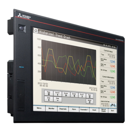
1.5 Equipment required for using GOT GOT external appearance and interface [Front face] Human sensor Simple design The GOT detects an operator and The stylish and simple design with a linear motif is sleek and displays its screen automatically. complements any machine design. - Page 23 Required equipment The equipment required to connect the GOT to the PLC CPU is shown below. Personal computer GOT2000 USB cable Connection cable GT Works3 Communication unit Equipment name Application [1] Personal computer Device to be used for writing the data stored in GOT. [2] GT Works3 Device to be used for writing the data stored in GOT.
- Page 24 What is GT Designer3 GT Designer3 is software to create screens for GOT2000 series and GOT1000 series. This software enables you to create and simulate a project, and transfer data between the GOT and a personal computer. Project creation Simulation Data transfer Personal computer (GT Designer3)
- Page 25 Operating environment for GT Designer3 Item Description Model Personal computer that Windows runs on. • Microsoft Windows 10 Enterprise (32 bit, 64 bit) *1*2*4*6 • Microsoft Windows 10 Pro (32 bit, 64 bit) *1*2*4*6 • Microsoft Windows 10 Home (32 bit, 64 bit) *1*2*4 •...
- Page 26 Item Description To use the simulation function on a personal computer, one of the following software applications must be installed. • GX Simulator3 (included in GX Works3 Version1.007H or later) • GX Simulator2 (included in GX Works2 Version1.12N or later) •...
- Page 27 • Software version of GX Simulator Software version of PLC CPU compatible with simulation GX Simulator QCPU (A mode), ACPU, motion controller CPU (A series) Version5.00A or later QnACPU Version5.40E or later FX0 series, FX0N series, FX0S series, FX1 series, FX1N series, FX1NC Version5.40E or later series, FX1S series, FX2 series, FX2C series, FX2N series, FX2NC series QCPU (Q mode) (except for Q00J, Q00, and Q01CPU)
- Page 28 • Software version of GX Simulator3 Software version of PLC CPU compatible with simulation GX Simulator3 R04CPU, R08CPU, R16CPU, R32CPU, R120CPU Version1.007H or later R08PCPU, R16PCPU, R32PCPU, R120PCPU Version1.010L or later R08SFCPU, R16SFCPU, R32SFCPU, R120SFCPU, R04ENCPU, Version1.020W or later R08ENCPU, R16ENCPU, R32ENCPU, R120ENCPU FX5U series, FX5UC series Version1.025B or later •...
- Page 29 List of software applications included in GT Works3 GT Designer3 (GOT2000) Version1 This software is used to create screens for GOT2000 series. GT Designer3 (GOT1000) Version1 This software is used to create screens for GOT1000 series. GT Designer2 Classic This software is used to create screens for GOT900 series.
-
Page 30: Applicable Connection Type Between The Got And The Plc Cpu
1.6 Applicable connection type between the GOT and the PLC CPU The GOT can perform monitoring by connecting it to the PLC using the following connection types. Therefore, the connection type suitable for the system configuration or usage can be selected. (1) Ethernet connection GOT can be connected to the Ethernet connection. - Page 31 (4) Bus connection Bus connection is a method using an extension connector of a base unit to connect a GOT (connection by I/O bus). This connection type enables the fastest response to a PLC CPU among all GOT connection types. By occupying one stage of the extension base unit, up to maximum five GOTs can be connected.
- Page 32 (7) CC-Link IE Field Network connection CC-Link IE Field Network is a high-speed and large-capacity Field Network that handles a mix of control data and management data of devices. Additionally, distribution of controllers, I/O control, motion control, and safety functions can be seamlessly set. QCPU Partner manufacturer (8) Applicable connections with third party PLCs...
-
Page 33: Connection To Equipment Other Than The Plc
Connection to equipment other than the PLC (1) Microcomputer Data can be read and written from a personal computer, microcomputer board, PLC to GOT virtual devices. (2) Bar-code reader The data read with the bar-code reader can be written to PLC CPU. (3) Temperature controller, Inverter, Servo amplifier, CNC The controllers can be monitored and modification in parameters is also possible. -
Page 34: Multi-Channel Function
Channel No. 4 Servo amplifier connection To use the multi-channel function, read the GOT2000 Series Connection Manual (Mitsubishi Electric Products) and select systems and the communication units to be mounted on a GOT. 1 - 22 1. What is the GOT? -
Page 35: Got Operation
GOT operation GOT enables reading and writing to PLC CPU devices (bit, word) with the switches, lamp, numerical display/input, message display, etc. on the GOT screen. 2.1 Summary of operation With GT Designer3, display pane figures called objects, such as the touch switch, lamp, and numerical display, etc., are pasted on the GOT screen. -
Page 36
While the touch switch "Run" on the GOT is (GOT) (PLC CPU) being touched, the bit device "M0" has been ON. Touch. Turns ON. Run lamp Run Stop Data MOV K123 D10 When the bit device "M0" turns ON, the bit (PLC CPU) (GOT) Turns ON. - Page 37 To change the value of the word device "D10", (GOT) touch the numerical input on the GOT. Run lamp Stop Data Touch. Input the numerical value on the key window to (GOT) be displayed. To store the value, touch the [Enter] button. Run lamp Run Stop Data...
- Page 38 2 - 4 2. GOT operation 2.1 Summary of operation...
-
Page 39: About Gt Designer3
GT Designer3 (GOT1000) can be installed from the DVD-ROM or CD-ROM of GT Works3. Creating or editing a GOT900 project To create or edit a GOT900 project, use GT Designer2 Classic. GT Designer2 Classic can be downloaded from the MITSUBISHI ELECTRIC FA Global Website. 3. About GT Designer3 3 - 1... -
Page 40: Gt Designer3 Screen Configuration And Features
3.2 GT Designer3 screen configuration and features 3.2.1 Screen layout of GT Designer3 The following shows the screen layout, toolbars, and windows of GT Designer3. Item Description Displays the software name. 1) Title bar The title bar displays a project name (workspace format) and a file name with a full path (single file format) according to the format in which the project is being edited. - Page 41 Item Description A window that can be docked with the screen of GT Designer3. The docking location can be customized. The following shows the types of windows that can be docked. [Utilize (Screen)] window Searches a screen of another project which can be utilized. [Project] window Displays the list of the settings of the whole project.
-
Page 42: Features Of Gt Designer3
3.2.2 Features of GT Designer3 The following shows the features of GT Designer3. (1) Categorized setting items enable users to select an item easily. (Work tree) Setting items in a project are categorized into "Project", "System", and "Screen" so that users can find an appropriate item easily. - Page 43 (3) Parts to be used frequently can be registered. (Library) The tree view enables users to easily search for an item in the library. Objects can be selected not only from [Appearance], but also from [Function] or [Recently Used Library]. Just by selecting parts from the library and placing them on the editor, a beautiful screen can be created easily.
- Page 44 (6) Easy alignment (Editor) When a figure or object is dragged to move, the line display target exists in the horizontal or vertical direction for easy alignment of objects. You can place figures and objects with the help of guidelines (auxiliary lines). (7) Easy placement using the consecutive copy (Editor) Figures or objects can be copied for a specified number all at once.
- Page 45 (9) Data browser The common setting, figures, and objects set in the project are displayed in a list. The targets to be displayed in the data browser can be changed and the displayed settings can be changed collectively. Example) When the [Text Batch Edit] is selected from the menu (10) Simulation with just one click (Simulator) Use a personal computer to check the screen data operation.
- Page 46 (11) The required data is selected automatically. (Communication with the GOT) GT Designer3 (2000) selects the required system application, communication driver, and special data automatically from the project setting, adds them to the package data , and while transferring it to GOT. The following shows the three methods for transferring data to the GOT.
-
Page 47: How To Use Help
3.3 How to use Help 3.3.1 Displaying Help (1) Displaying Help from the menu To display Help, select [Help] → [GT Designer3 Help] from the menu. (2) Displaying a page corresponding to the operation status of GT Designer3 To display a page corresponding to the operation status of GT Designer3, press [F1] key while operating GT Designer3. - Page 48 3 - 10 3. About GT Designer3 3.3 How to use Help...
-
Page 49: From Got Screen Creation Up To The Test
From GOT screen creation up to the test 4.1 Preparation before using the GOT This section describes the procedure of creating screens up to monitoring of PLC by the GOT. Install the software package (GT Designer3 (GOT2000) and Help) (Refer to the GT Works3 Installation Instructions). Create project data (GT Designer3 (GOT2000)). -
Page 50: Screen Creation
4.2 Screen creation 4.2.1 Project creation Projects comprise all the data and settings displayed in one GOT. The screens displayed in the GOT and connection method with the PLC are set in a project wizard. In this section, the settings for the type of GOT used for training and the type of PLC connected to the GOT are described. - Page 51 (1) System settings for GOT The GOT type to be used and the color are set. When the left screen appears, set the GOT type and the color as follows. GOT Type: GT27**-S (800x600) After the selection is made, click the button.
- Page 52 (From previous page) When the left screen appears, set the communication driver as follows. Communication Driver: Ethernet(MELSEC), Q17nNC, CRnD-700, Gateway Click the button. On the screen shown left, click the button. On the screen shown left, set the GOT IP address as follows.
- Page 53 (From previous page) Click the button. The left screen is displayed. Confirm the settings. Click the button. If GT Designer3 (GOT1000) starts while GT Designer3 is running, start GT Designer3 (GOT2000) by using one of the following methods. (1) Click [Project] → [Start GT Designer3 (GOT2000)] from the menu of GT Designer3 (GOT1000). (2) Select [GOT2000] and click the [Next] button in the [New Project Wizard] dialog of GT Designer3 (GOT1000).
- Page 54 (3) Setting of Screen Switch Device The device for switching the screens displayed on GOT is set. (The settings made here can be changed later.) Refer to section 4.2.3 for details on screen switching device settings. When the left screen appears, the screen switching device is set as follows.
- Page 55 a rk Changing the GOT type or screen title The GOT type and screen title settings can be changed in the docking window. • Changing the GOT type • Changing the screen title Double-click this item. 1. Right-click this item. 2.
-
Page 56: Communication Settings
4.2.2 Communication settings Settings described in this section are not required when settings are made on the new project wizard (Section 4.2.1). The GOT and PLC CPU communication settings are performed. When using the GOT for the first time, set the channel number and communication driver for the communication interface, and write the settings to the GOT. - Page 57 (From previous page) Configure the controller setting. Set the items as shown below. (Settings for this item have already been performed in the new project wizard described in section 4.2.1.) Manufacturer: MITSUBISHI Controller Type: MELSEC-Q/QS, Q17nD/ M/NC/DR, CRnD-700 I/F: Standard I/F(Ethernet):Multi Driver: Ethernet(MELSEC), Q17nNC, CRnD-700, Gateway Configure the detail setting as follows.
- Page 58 (From previous page) Configure the Ethernet setting as follows. Net No.: 1 (Virtual) Station: 2 (Virtual) Unit Type: QnUD(P)V/QnUDEH IP Address: 192.168.3.39 Port No.: 5006 Communication: UDP Click the button. I NT Ethernet setting When the GOT is connected to the Ethernet port built in the QnUDVCPU or other PLC CPUs via the Ethernet connection, the setting items [Net No.] and [Station] do not exist on the PLC side.
-
Page 59: Screen Switching Device Settings
4.2.3 Screen switching device settings This section explains screen switching device settings. Set the base screen switching device to "D0", and the Overlap window1 screen switching device to "D1". Click on the [Common] – [GOT Environmental Setting] – [Screen Switching/ Windows] menu. - Page 60 (From previous page) I NT In the [Detail Setting] dialog box, the following contents can be set. • [Close the window when switching base screens] Closes the overlap window automatically without [X] when the base screen is switched. • [Display the title bar] Displays a title bar on the overlap window.
- Page 61 Screen switching device settings With the screen switching device, refer to the following to set the devices to be used. GOT internal device (GD) It is recommended to use a GD device when screens are not switched by a PLC CPU. Switch between screens with a specific touch switch ([Go To Screen Switch]).
- Page 62 4.2.4 Saving the project data This section explains the operations to save the created project data. This section explains to save a project to a desktop with an example. Click on the [Project] – [Save As] menu. The [Save As Project] dialog appears. (Next page) 4 - 14 4.
- Page 63 (From previous page) Select "Desktop" for [Save in]. Set the file name of the project to be saved as follows. File name : "kiso" Save as type : Project Data(*.GTX) Click the button to save the project. 4 - 15 4.
- Page 64 a rk Select [Project] → [Save As] from the menu to display the [Save As Project] dialog. • Single file format: Save the project in the [Save As Project] dialog. • Workspace format: Save the project in the [Save As Project] dialog. In this textbook, the project is saved in the single file format.
- Page 65 The workspace format project is the file format to manage multiple projects in the workspace. The workspace format project consists of multiple folders and files as the figure below. Storage folder Workspace folder 2 Workspace folder 1 Workspace Project Project Project folder Project folder management file...
-
Page 66: Reading Screens
4.2.5 Reading screens In this section, training is performed using screen prepared beforehand. (Specific creation methods for screen are explained in chapter 5.) Screen data is loaded from the project named "school" for which the settings described in sections 4.2.1 and 4.2.2 are configured. - Page 67 (From previous page) The [Open Project] dialog box appears and select "school.GTX". Click the button. As the dialog box to confirm whether to save the project data created this time appears, click the button. (Next page) 4 - 19 4. From GOT screen creation up to the test 4.2 Screen creation...
- Page 68 (From previous page) The screen is read. a rk Select [Project] → [Open] from the menu to display the [Open Project] dialog. • Workspace format: Open the project from the [Open Project] dialog (workspace format). • Single file format: Open the project from the [Open Project] dialog (single file format). In this textbook, a project in the single file format is opened.
-
Page 69: Data Transfer (Personal Computer To Got)
4.3 Data transfer (personal computer to GOT) This section explains procedures for writing data created on GT Designer3 to the GOT. 4.3.1 Connection from a personal computer to GOT Connect the personal computer and GOT. Notebook personal computer To USB To USB connector USB cable... -
Page 70: About Data Types Transferred To The Got
4.3.2 About data types transferred to the GOT To operate the GOT, it is necessary to transfer the following types of data to the GOT. Data type Outline Data transfer timing • When restoring the factory The program needed to control GOT hardware, and during communication between GOT and personal computers. -
Page 71: Communication Settings
4.3.3 Communication settings Settings for communication between the personal computer and the GOT are performed. Click on the [Communication] – [Communication Configuration] menu. In the [Communication Configuration] dialog, set the connection method and the connection interface as shown below. Connection to GOT: Direct PC side I/F: USB (In training, to connect the personal computer and GOT with the USB cable) -
Page 72: Writing The Package Data
4.3.4 Writing the package data This section describes how to write package data to the GOT. Click [Communication] → [Write to GOT] from the menu. When the [Communication Configuration] dialog appears, configure the settings as follows and click the button. Connection to GOT: Direct PC side I/F: USB (Next page) - Page 73 The [Communicate with GOT] dialog appears. Click the [Write Option] button to display the [Write Option] dialog. <[Communicate with GOT] dialog box> Write Data: Select the type of the data to be written to the GOT. Data Size: Displays the size of the data to be written to the GOT. Destination Drive: Select a GOT drive to which the project data or system applications are written.
- Page 74 (From previous page) Select [Package Data] in [Write Data]. Click the button. Select [Select] of [Write Mode]. Select the data to write. Click the button. Click the button. (Next page) 4 - 26 4. From GOT screen creation up to the test 4.3 Data transfer (personal computer to GOT)
- Page 75 (From previous page) Click the button to write the screen data. When writing the data is completed, a completion message appears. Click the button. After writing the data has been completed, the GOT restarts automatically. I NT Transferring data via a PLC GOT screen data can be transferred from a personal computer to the GOT via a PLC.
-
Page 76: Connection To Plc Cpu (Ethernet Connection)
4.4 Connection to PLC CPU (Ethernet connection) 4.4.1 Connecting the cable This section explains connection procedures for connecting the GOT and PLC CPU with the Ethernet connection cable. Power OFF the PLC CPU and GOT. Connect the Ethernet connection cable to the PLC module. -
Page 77: Checking Whether Data Has Been Properly Transferred To The Got
4.5 Checking whether data has been properly transferred to the GOT 4.5.1 System alarm The system alarm is a function used to display error codes and error messages when error occurs in the PLC, GOT, servo amplifier, communication system, etc. Error messages displayed in the system alarm do not need to be registered. -
Page 78: Executing The Monitor
4.5.2 Executing the monitor Operate the screen written to the GOT, and monitor the PLC. GOT Operation Image Lamp is lit when Y70 is turned ON. Lamp is lit when Y71 is Displays the value of D100. turned ON. Adds to the value of D100. Turn Y71 OFF. - Page 79 (2) Monitoring/changing the word device (D100) values To perform addition on the value of D100, touch a [Numeral Increase] switch. When the [Set Numeral] switch is touched, the D100 value is set. (3) Displaying the error message Power OFF the training machine and power OFF the PLC.
- Page 80 Checking package data Check whether the package data has been properly written to the GOT using GT Designer3. Click [Communication] - [Read from GOT] from the menu. The [Communicate with GOT] dialog appears. Select [Drive Information] in [Read Data]. Select [C:Built-in Flash Memory] in [Source Drive].
- Page 81 I NT Checking that the GOT recognizes the connected equipment Check that the GOT recognizes the connected equipment with the GOT utility. To avoid problems, always perform checks. Power ON the GOT. Utility call key Hold down the upper left corner for two seconds.
- Page 82 (From previous page) In [Ethernet I/F assignment], check that the Ethernet I/F setting of the channel No. 1 has been set to [Ethernet (standard I/F)]. When the target communication driver is not set, perform one of the following operations. Change the communication driver settings Touch the [Channel - Driver assign] button in the "Communication setting"...
-
Page 83: Drawing Fundamentals
Drawing fundamentals This chapter explains how to create screens on the GOT. The screen data created in this chapter works with the sequence program described in section 5.12. 5.1 Switching the screen to be displayed 5.1.1 The screen type The GOT2000 comprises the following screen types. Base screen Superimpose window 1, 2 Back... -
Page 84: Screen Switching Device
a rk • Up to 4096 base screens and up to 1024 window screens can be created. • For base screens and window screens, the range of registerable screen numbers is 0 to 32767. • For the display position setting of window screens, refer to the GT Designer3 (GOT2000) Screen Design Manual. - Page 85 (2) Screen switching of overlap windows and superimpose windows The GOT displays the window screen whose screen No. is the same as the value of the screen switching device as an overlap window or a superimpose window. Example) Setting D100 for the screen switching device of an overlap window Window screen: 10 Window screen: 20 The GOT displays a window...
- Page 86 (3) Screen switching of dialog windows The following two methods are available to display a created dialog window. • Displaying a created dialog window as a new message Storing the screen number of the created dialog window to the screen switching device enables the display of the dialog window.
-
Page 87: Base Screen Switching With The Sequence Program
5.1.3 Base screen switching with the sequence program GOT display screen is switched when the screen switching device value is written with the sequence program. Example: When the switching device for base screen is D0 Sequence program example Screen No. 6 MOV K2 Data 2 1234 MOV K3... -
Page 88: Base Screen Switching With The Touch Switch
5.1.4 Base screen switching with the touch switch GOT display screen is switched when the screen switching device value is written with the touch switch. Example: In the case of device for base screen switching: D0 Screen No. 5 RUN lamp No. -
Page 89: Window Screen Display And Switching
5.1.5 Window screen display and switching The window screen is displayed by writing the same No. as the window No. of the screen to be displayed into the switching device used in overlap windows 1 to 5. Two types of writing in the screen switching device are available: writing with the sequence program, and writing with the GOT touch switch. - Page 90 [Screens to be created] Screens to be created in this chapter and a summary of screen switching are as follows: " " refers to the screen switching (page switching) operation. Base Screen No. 2 Base Screen No. 1 (Displays the error which occurred in GOT or PLC.) (Sets objects such as switch, lamp, numerical display, etc.) Window Screen No.
-
Page 91: Before Creating The Screen
5.2 Before creating the screen 5.2.1 Operations before creating the screen Set the project using [New Project Wizard] in the following manner: (1) System Settings for GOT GOT Type: GT27**-S (800x600) Color Setting: 65536 Colors (2) Confirmation Controller Type: MELSEC-Q/QS, Q17nD/M/NC/ DR, CRnD-700 I/F: Standard I/F(Ethernet):Multi Communication Driver: Ethernet(MELSEC),... - Page 92 (4) Screen Property Enter "Base screen". (5) Saving project data Save the project data. Select [Project] - [Save As] from the menu and save the current project with the name "BASIC1". 5 - 10 5. Drawing fundamentals 5.2 Before creating the screen...
- Page 93 5.2.2 Figure drawing This section describes how to draw figures and how to edit the figures arranged on the screen. (1) Types of drawable figures The following figures can be drawn on GT Designer3: Shape Drawing example Reference Text (5) Text settings Logo text Line (2) Drawing line, rectangle, and circle...
- Page 94 (2) Drawing line, rectangle, and circle This section describes how to draw a line using an example. Click on the toolbar (Figure). Drawing rectangle: Click Drawing circle: Click Click the left mouse button at the starting point for drawing a line. Start point Drag and move the cursor to the end point.
- Page 95 (From previous page) Release the left mouse button to draw a line. Start point End point (3) Drawing polygon and line free form This section describes how to draw a polygon using an example. Click on the toolbar (Figure). Drawing line free form: Click Click the left mouse button at the starting point for drawing a polygon.
- Page 96 (From previous page) Drag and move the cursor to the second vertex. Start point Release the left mouse button to determine the second point. Second point Click the left mouse button at the third vertex. Repeat this procedure to increase the Start point number of vertexes.
- Page 97 (4) Drawing arc and sector This section describes how to draw an arc using an example. Click on the toolbar (Figure). Drawing sector: Click Click the left mouse button at the starting point for drawing an arc. Start point Set the starting point and the endpoint of a radius.
- Page 98 (From previous page) Drag and move the cursor to the end point. Release the left mouse button. A line from the Start point center of the circle is drawn. End point Drag and move the cursor to define the starting point of arc. Start point of arc Set the starting point and the endpoint of an arc.
- Page 99 (From previous page) Click to form an arc. a rk Drawing sector Double-click the drawn arc and check [Sector] in the Arc/Sector dialog box to draw a sector. 5 - 17 5. Drawing fundamentals 5.2 Before creating the screen...
- Page 100 (5) Text settings This section describes how to set a text (input a text). Click on the toolbar (Figure). Click the left mouse button at the starting point for placing a text. The setting dialog appears. (Next page) 5 - 18 5.
- Page 101 (From previous page) Enter a character string. Enter "GOT2000 series" here. After entering the character string, click the [OK] button. The character string is displayed. 5 - 19 5. Drawing fundamentals 5.2 Before creating the screen...
- Page 102 (6) Selecting data for editing This section describes how to select the desired figure/object for editing. Click on the toolbar (Main). To select data, first click the left mouse button Start point at the starting point to drag and move the cursor to the end point, and then release the left mouse button to include all the data necessary.
- Page 103 (7) Changing attribute Change the attribute of the created figure on the property sheet. This section describes how to change the color for a circle using an example. Select the figure. Change the attribute on the property sheet. Change the pattern color from [None] to [Fill Color (White)] for the circle.
- Page 104 (From previous page) The changes made are reflected on the figure. 5 - 22 5. Drawing fundamentals 5.2 Before creating the screen...
- Page 105 To change attributes other than the pattern figure color, use the following items of the property sheet. [Line Style] Select a line style of the figure. [Line Width] Select a line width. [Line Color] Select a line color. [Pattern] Select a filling pattern for the figure. [Shape Color] Select a fill color of the figure.
- Page 106 (8) Size change This section describes how to expand/reduce the size of figure/object. Select a figure/object of which the size needs to be changed. Click the left mouse button on the handle ( ● on the direction to which the figure is expanded/reduced, and then drag the cursor.
- Page 107 (9) Moving selected data This section describes how to move the figure/object. Select the figure/object to be moved. Move the cursor to the figure/object to be moved to change the cursor shape into Click the left mouse button and drag the figure/object to the desired position.
- Page 108 (10) Cutting, copying, pasting, or duplicating the selected data The following shows how to cut, copy, paste, or duplicate a figure or object. Cut and paste Select the desired figure/object. For cutting, click on the toolbar (Main). (For copying, click I NT •...
- Page 109 Pasting This section describes how to paste the cut or copied figure/object using an example. Click on the toolbar (Main). A display range frame appears. Move it to the desired position. Click the mouse button to paste the cut figure/object. •...
- Page 110 Duplicate Copies and pastes a selected figure or object at a time. Select a figure or an object placed on the screen editor and use [Duplicate]. Select a figure or an object. Select [Edit] → [Duplicate] from the menu. The selected figure or object is copied and pasted with a certain interval.
-
Page 111: Text Settings
5.3 Text settings This section describes how to create actual screens. Screen Screen No. 1 No. 2 Window No. 1 The following characters will be placed on Base Screen No.1. Set a title and a unit by using text figures. (Select a standard font or the outline gothic font in the text figure setting.) (1) Click... - Page 112 (3) Set the attributes for the entered characters. Style The following text styles are available. Standard Bold Solid Raised Reverse Rotate/Flip Font Font Image Classification Type Outline Square style Outline font Outline Gothic 6 × 8 dots (Gothic) 12-dot Standard (Gothic) Standard font 16-dot Standard (Mincho) 16-dot Standard (Gothic)
- Page 113 (4) Click the button. "Planned operating time" is displayed on the screen. 5 - 31 5. Drawing fundamentals 5.3 Text settings...
- Page 114 5.4 Numerical input/numerical display settings This function is used to write or display the data stored in the devices of the controller. Screen Screen In this section, create a numerical display showing the operating time, and a numerical input for No.
-
Page 115: Numerical Input/Numerical Display Settings
Changing the size of an object after being placed This section describes how to change the size of arranged object. Select the object to be changed in size. Position the cursor on the sizing handle, click and drag it to change the object size. 5 - 33 5. - Page 116 Making basic settings Set [Type] to [Numerical Input]. Click the button. Set "D10" for [Device]. After setting is completed, click the button. Setting the display format (to handle decimal number in a range of 0 - 9999) Set [Format] to "Signed Decimal". Set [Digits (Integral)] to "4".
- Page 117 Making settings on the screen Use text figure to assign unit to numerical input. This completes the settings of the numerical input. 5 - 35 5. Drawing fundamentals 5.4 Numerical input/numerical display settings...
-
Page 118: Numerical Display Settings
5.4.2 Numerical display settings Making the settings of numerical display (D20) (1) Click on the toolbar (Object), and then click any where on the drawing screen. (2) Double-click the numerical display, and make the settings as follows: (the same procedures as those described in section 5.4.1) Set "D20"... -
Page 119: Key Window
5.4.3 Key window The key window has two types: GOT default key window (standard key window) and key window created by the user (user-created key window). (1) Standard key window The standard key window is a GOT default window for inputting numerical values and characters. The type of the standard key window to be displayed changes automatically according to the data type of the input area (hexadecimal number, decimal number, octal number, binary number, or character string). - Page 120 (2) User-created key window By displaying a user-created window screen as a key window, it can be used as the user's original key window. Example) User-created key window (for text input) Example) User-created key window (for numerical input (decimal)) By registering a user-created window screen as a key window, the key window for numerical input can be used as the user's original key window.
-
Page 121: Settings Of Lamps
5.5 Settings of lamps This function is used to turn on/off the lamp depending on the bit device condition (on/off) or the value Screen Screen of word device. No. 2 No. 1 In this section, create a lamp that turns on when Y7A is on. Window No. - Page 122 (From previous page) Select [FA Metal_N Lamp 1] in the [Library] folder. Click the toolbar option and set the lamp color to "Green". Click "68 L_05_G". (Next page) 5 - 40 5. Drawing fundamentals 5.5 Settings of lamps...
- Page 123 (From previous page) On the screen, click the mouse button to place the lamp. Double-click the placed lamp to display the setting dialog. (2) Settings of lamps Set [Device] to "Y7A". When setting is done, click the button. (3) Making settings on the screen Use text figure to create title for Lamp.
-
Page 124: Touch Switch Settings
5.6 Touch switch settings Make the settings for the switches which behave as follows when touched. Screen Screen • Bit Switch : Turns bit device ON/OFF when touched. No. 2 No. 1 • Go To Screen Switch : Switches base screen/window screen when touched. Window No. - Page 125 (2) Bit switch settings Click the button in [Switch Action]. As the device setting dialog box appears, set the device to "M10". After setting is completed, click the button. Set [Action]. [Action] determines how the bit device will behave when touched. •...
- Page 126 (3) Setting a display style Click the [Style] tab. Click the button. (Next page) 5 - 44 5. Drawing fundamentals 5.6 Touch switch settings...
- Page 127 (From previous page) As the [Image List] dialog box appears, select the figure "33 SW_02_0_B". After setting is completed, click the button. Set the shape attribute for the OFF state as follows. Shape Color: Blue Click the shape of the ON state to set the shape attribute for the ON state.
- Page 128 (4) Creating other bit switches Copy the touch switch created in (2) and paste the copy to create a new touch switch. The following shows how to copy and paste a touch switch. Click the copy target touch switch to select it. Click on the toolbar.
- Page 129 To adjust the touch area of a touch switch according to the switch size, perform the following operations. Effective area for touch switch Touch switch size Right-click the mouse and select [Edit Touch Area] → [Manual Edit] from the menu. Change the size of the touch switch effective area so that it overlaps the touch switch figure size.
-
Page 130: Bit Switch Actions
5.6.2 Bit switch actions A bit switch turns on and off the bit device specified by the switch. The following shows the actions that can be set with bit switches. (1) Bit momentary Keeps a specified bit device on only while you touch the switch. X0001: OFF X0001: ON X0001: ON... -
Page 131: Operation Check 1
5.7 Operation check 1 Select [Communication] → [Write to GOT] from the menu to display the screen for writing project data. Select data and a write mode, and then click the [GOT Write] button to write all data to the GOT. Reset the PLC CPU using the RESET key switch, and then switch to RUN. - Page 132 (4) Test 4 Perform the following tests in screen No. 1. Test object Operating time Reset switch RUN lamp (numerical display) Item ──── ──── Touch Touch operation The operating time Screen status The switch is pressed. The lamp is off. becomes "0".
-
Page 133: Comment Display Settings
5.8 Comment display settings Two types of messages (comments) are displayed depending on the condition of devices. Screen Screen No. 1 No. 2 Window No. 1 Describes the line operation (Y7B: ON/OFF) of comment display in the form of comment. With Y7B ON, "line in operation"... -
Page 134: About The Comment Display
5.8.1 About the comment display There are the following three types of comment display. (1) Comment display (bit) It is the function to display the comment corresponding to the ON/OFF status of bit device. The following two comments are switched back and forth for displaying. X10 = OFF X10 = ON Pro. -
Page 135: Comment Display Settings By Bit Device
5.8.2 Comment display settings by bit device (1) Registering comments Double-click [New] of the [Comment] menu in the project tree. When [Comment Group Property] appears, configure the setting as follows. Group No.: 1, Line operating status Click the button. When the [Comment List] dialog appears, configure the settings as follows. - Page 136 Displaying multi-language comments (Language switching device) If you set multiple comment columns in a comment group, the comments can be registered in multiple languages for one comment No. The comments registered in multiple languages can be switched by switching the comment column to be displayed with the language switching devices.
- Page 137 (2) Click on the toolbar (Object) to place a comment on the object screen. (3) Comment display setting Double-click the comment display. The comment display (Bit) dialog box is displayed. Click the button to set the device to "Y007B". Click the [Comment] tab. Set [Font] to "Outline Gothic"...
- Page 138 (From previous page) Set comments to be displayed when the device is ON. Set [Comment No.] to 2. Click the button. A comment can be created with 1 to 1024 characters. Comments can be created on multiple lines. Comments are displayed in the GOT as follows: In operation now In operation now Y70 is ON.
- Page 139 (4) Settings on object screen Adjust the size of object frame so that all the comments are displayed. Create a frame for the comments. As the cursor changes to a re-sizing cursor when it is moved over to the handle, click the left mouse button and drag it to the desired size for displaying.
- Page 140 I NT • The display condition for set comments can be displayed switching between ON and OFF by pressing the "ON/OFF of object function" button on the toolbar (Display setting). • Adjust the size of display area when the comments vary in length depending on its ON/OFF condition as follows: (Example) In case of ON, [Alarm: The water level is at upper limit.].
-
Page 141: Window Screen Creation
5.9 Window screen creation Create a screen displayed over the base screen. Screen Screen Window screen No. 1 is displayed in Overlap window 1 here. No. 1 No. 2 Window No. 1 Displays the clock. (1) Making the settings of screen switch device Click the docked [System] tab. - Page 142 (From previous page) Check [Overlap Window1]. Click the button to set the device to "D1". Click the button. This completes the settings of the screen switching device. (2) Creating window screen Select the [Screen] - [New] - [Window Screen] menu. As a dialog box appears, check that the "Window Screen"...
- Page 143 (3) Setting the time displayed on the window screen The current time is displayed on the GOT. Click on the toolbar (Object). Click on the upper left portion of the screen to place a time display. Double-click the placed time display. The [Time Display] dialog appears.
- Page 144 Date and time displayed by time display function The time display function represents the date and time of the GOT maintained by the internal clock function. The clock function sets the clock to be used as standard for adjusting the time between the GOT and PLC CPU.
-
Page 145: System Alarm Settings
5.10 System alarm settings Create Base Screen No. 2 and set the system alarm. Screen Screen Refer to section 4.5.1 for details for system alarms. No. 1 No. 2 The following screen will be created in Base Screen No.2. Window No. - Page 146 (From previous page) Window screen No. 2 is displayed on the screen. (2) Creating a title text for the system alarm Enter "System alarm" in Text. (3) Setting a system alarm. Select Object- Alarm Display- System Alarm Display. Click on the screen to place a system alarm display.
- Page 147 I NT An adjustment of display area is required as illustrated below to keep part of alarm message from dropping out of the frame. 400 Unable to communicate with CPU Set in three lines. AC down error 803 Transient error Error message (Max.
- Page 148 a rk Misalignment of object and figure Centering the object in the figure Right click on the object to be realigned. Right-click the mouse and select [Centering] in menu. Moving the object to any position within the figure The position of object and shape can be changed separately as instructed below. Right-click the mouse and select [Edit Move the object to change the Touch Area] →...
-
Page 149: Go To Screen Switch Setting
5.10.2 Go To Screen Switch setting Create a switch which can switch a base screen to another or display a window screen by touch operation. (1) Placing a Go To Screen Switch. Display Base Screen No. 1. Select the [Object] - [Switch] - [Go To Screen Switch] menu. -
Page 150
(3) Setting the display (figure, color) of Go To Screen Switch. Click the [Style] tab. Set the Display Style of Go To Screen Switch as follows: "Shape": FA Control Switch Figure A1:SW_02_0_W (specified in Shape...)
[Shape Color]: White ... - Page 151 (From previous page) Set the text to be displayed in the switch as follows: [Font] : Outline Gothic [Text Size] : 12 [Text Color] : Black Set the display position of text as follows: [Display Position]: Center [Alignment]: X: The position of the texts used for switches and lamps can be selected among the following display positions: Left Switch figure Right...
-
Page 152: Operation Check 2
5.11 Operation check 2 Display the screen for writing a project, and then write data to the GOT. Reset the PLC CPU using the RESET key switch, and then switch to RUN. Check if the comment display in screen No. 1 is properly displayed, and that the overlap window (Window Screen No. 1) appears correctly here. - Page 153 (4) Test 4 Perform the following tests in screen No. 1. Test object Alarm screen switch Item 1) Touch operation Touch Screen status Switch to Base Screen No. 2. 2→D0 Write device ──── Read device (5) Test 5 Perform the following tests in screen No. 2. Test object System alarm Item...
- Page 154 (8) Test 8 Perform the following tests in screen No. 1. Test object Window screen Item 1) Touch operation Touch x in the upper right corner. Screen status Window screen No. 1 closes. 0→D1 Write device ──── Read device 5 - 72 5.
-
Page 155: Training Device List And Sequence Program
5.12 Training device list and sequence program (1) Training device list Device Signal name Device Signal name operation operation Line start/stop Numerical input Reset Numerical display RUN lamp Base screen switching Comment display Window screen switching R: Reading W: Writing I NT To identify the device used for the project data being edited, the Device List function of GT Designer3 will be useful. -
Page 156: How To Check The Devices Used In The Created Project
5.13 How to check the devices used in the created project To check the devices used in the created project, use the device list on GT Designer3. Display the list of the devices used in the project which has been created in this training. Click the [Search/Replace] - [Device List] - [Project] menu. -
Page 157: About Debug
About debug This chapter describes the debug function used for troubleshooting and maintenance of the PLC system. 6.1 Extended function To use extended functions, install the extended system applications on the GOT. (1) List of extended functions Function name Reference Graphic acceleration driver Standard font Outline font... - Page 158 Function name Reference Recipe operation Recipe display (record list) GT Designer3 (GOT2000) Screen Design Manual Operation log screen image Operator authentication File manager GOT2000 Series User's Manual (Utility) Document display GT Designer3 (GOT2000) Screen Design Manual MELSEC-L troubleshooting function GOT2000 Series User's Manual (Monitor) GOT platform library GT Designer3 (GOT2000) Screen Design Manual GOT function expansion library...
- Page 159 (2) Writing the extended functions The following explains the procedure for writing the extended functions. In this section, the sequence program monitor (ladder) and device monitor for training in section 6.3 and section 6.4 are written. Click [Communication] - [Write to GOT] from the menu.
- Page 160 (From previous page) Select [Extended Function] - [Sequence Program Monitor(Ladder)] and [Device monitor] from the tree view, and click the button. Click the button. 6 - 4 6. About debug 6.1 Extended function...
-
Page 161: Training Screen Creation
6.2 Training screen creation Add the following Base Screen No. 3 to the screen created in chapter 5. Base Screen No. 3 Numerical display Displays the operating time of the line. (D32: hours, D31: minutes, D30: seconds) Bit lamp Bit lamp Turns on during Lit if the operating display line operation (M34). - Page 162 (From previous page) Place the numerical display, and make the settings as follows: [Device] tab Device: D30 Font: Outline Gothic Number Size: 32 Digits (Integral): 2 Select [Fill with 0]. Copy and paste the numerical display created in , and make the settings as follows: 1) Device "D31"...
- Page 163 (From previous page) Select [Object] - [Switch] - [Bit Switch] and click a desired position on which a bit switch is to be placed. Change the width of the switch and configure the settings as follows. [Device] tab Device: M31 Action: Alternate [Style] tab Shape: FA Control Switch Figure A1...
-
Page 164: Writing A Project
6.2.2 Writing a project Display the screen for writing the project and write all data to the GOT. Reset the PLC CPU using the RESET key switch, and then switch to RUN. 6.2.3 Training sequence program To identify the device used for the project data being edited, the Device list function of GT Designer3 will be useful. Refer to section 5.13 of this textbook for details. -
Page 165: Sequence Program Monitor (Ladder)
6.3 Sequence program monitor (Ladder) 6.3.1 Sequence program monitor (Ladder) (1) Features With the sequence program monitor (ladder) function, you can use the GOT to monitor or edit the sequence program of a controller in the ladder diagram format and change the current device values. This function supports the display switching (decimal or hexadecimal format), the display of the device comments written to a PLC CPU, and the display language switching. - Page 166 (3) Required extended system application The following extended system applications are required. • Sequence program monitor • GOT platform library • GOT function expansion library (4) Required hardware The following hardware is required. Hardware Data storage (SD card, USB memory, and etc) 6 - 10 6.
-
Page 167: Operation Check (1)
6.3.2 Operation check (1) Perform the following operation checks for screen No.3 created in section 6.2. (1) Test Perform the following tests in screen No. 3. Test object Operation Item 1) Touch operation Touch Run/Stop. (Under normal conditions) The Operating lamp turns ON, and the operating time starts counting. -
Page 168: Startup Procedure Of Sequence Program Monitor (Ladder)
6.3.3 Startup procedure of sequence program monitor (Ladder) Hold down the upper left corner of the GOT Utility call key monitor screen for two seconds. Hold down the upper left corner for two seconds. Touch [Monitor] tab. Touch [Monitor]. Touch [Seq. program monitor (Ladder)]. Touch [Seq. - Page 169 (From previous page) The communication setting window appears. 1) The names of the communication drivers installed on the GOT are displayed. 2) The channel No. is fixed to "1". Touch to move the cursor to network No. [ ]. Set the network No. to [0]. Set the station No.
- Page 170 (From previous page) On the [PLC Read] screen, select [Program Memory] from the target drive list of [PLC Drive] to list the files stored in the drive. Touch the key to select the sequence program displayed in the file list. Touch the key to write the sequence program to the data storage device...
- Page 171 (From previous page) The sequence program file selected in the list of files (connection destination) is displayed in the ladder monitor screen, and functions including the device search can be used. 6 - 15 6. About debug 6.3 Sequence program monitor (Ladder)
-
Page 172: Method For Factor Search Operation
6.3.4 Method for factor search operation The factor search function searches the ladder blocks for the conductive/non-conductive status of the contact that turns on or off a specific coil when the sequence program monitor (ladder) is performed. This section explains the operation procedures. Touch [Find]. - Page 173 (From previous page) Touch the [M] key to enter "M" into [Factor], and touch [0-9] to display the number keys. Set the device number to "34". Touch the [Enter] key. The block containing the specified device is displayed, and the device is enclosed in a green frame.
-
Page 174: Operation Check (2)
6.3.5 Operation check (2) Display the screen for writing a project, and then write data to the GOT. Reset the PLC CPU using the RESET key switch, and then switch to RUN. (1) Test Perform the following tests in screen No. 3. Test object Operation Item... -
Page 175: Device Monitor Function
6.4 Device monitor function 6.4.1 About the device monitor function (1) Features The device monitor function monitors and changes the devices of a PLC CPU or an intelligent module. With this function, you can troubleshoot the system and streamline maintenance. (2) Monitoring method available with system monitor function Monitoring method Description... -
Page 176: Method For Starting The System Monitor
(4) Required extended system application The following extended system application is required. System application Device monitor GOT platform library 6.4.2 Method for starting the system monitor Hold down the upper left corner of the GOT Utility call key monitor screen for two seconds. Hold down the upper left corner for two seconds. -
Page 177
(From previous page) The Device monitor screen appears. Touch the [Connect] key. Touch [Connect]. The communication setting window appears. Configure the settings as follows.
Ch No : 1 (Set a number using the channel No. selection keys.) Page 178: Operation Check (Device Monitor Operation)
6.4.3 Operation check (device monitor operation) In this section, the following operation checks are performed regarding the training screen created in section 6.2 using the device monitor of the system monitor function. Numerical display Displays the operating time of the line. (D32: hours, D31: minutes, D30: seconds) Bit lamp Lit if the operating display exceeds eight hours...- Page 179 (From previous page) The entry monitor screen appears. Touch the [Register] key. Touch [Register]. The device registration window appears. Touch the device display area. Set the device number to "D30". Touch the [Enter] key. (Next page) 6 - 23 6. About debug 6.4 Device monitor function...
- Page 180 (From previous page) Register the device. Registering the device now. Please Wait. When registration is complete, return to the device registration screen. Touch the [AC] key to clear the device value. Set the device number to "D31" and touch the [Enter] key to register the device.
- Page 181 (2) Operation procedure for test operation Touch the [Test] key on the device monitor screen. Touch [Test]. The confirmation dialog is displayed. Touch the [OK] key to switch to the test mode. Touch a device targeted for the test operation. (Next page) 6 - 25 6.
- Page 182 (From previous page) The device value setting window appears. Set the device value as follows and touch the [Enter] key. D30: Device value = 50 After the setting has been completed, touch [×] to exit the device value setting window. Set the following devices in the same manner.
- Page 183 (From previous page) Touch the [Test] key again to end the test mode. Touch the [Quit] key on the Device monitor screen. Touch [Test]. When the Main menu screen appears, touch [x]. 6 - 27 6. About debug 6.4 Device monitor function...
- Page 184 (3) Operation check Display Base screen No. 3. Check that the operating time indicates 7:59:50. Turn on X2, and touch the [Run/Stop] switch to start counting the operating time. When the operating time exceeds eight hours, check if the lamp turns ON. 6 - 28 6.
Page 185: Appendices
Appendices Appendix.1 Alarm Appendix.1.1 About the alarm The alarm display function displays the user-created comments as alarm messages, or displays the error codes and messages of the GOT, controllers, or networks. This function monitors the devices, GOT, controllers, and networks, and collects alarm data from them. This chapter explains the functions that display following alarms.- Page 186 (2) Available functions in the alarm The GOT collects and displays alarms as follows. Available functions in the alarm Description Remarks The following display methods are available: • Displaying comments by level in the Displaying the comment set previously at the You can register any comment for the hierarchy alarm occurrence...
- Page 187 Appendix.1.2 Collecting alarms by monitoring devices In a user alarm monitor, the time when set conditions of devices set as the alarm detection are satisfied or comments as the user alarm data history to a built-in memory of the GOT. The alarm detection condition An alarm set by the user is satisfied.
- Page 188 Specifications of the user alarm observation (1) Alarm detection condition and range Detection condition • Rising (OFF to ON) or falling (ON to OFF) of the bit device • Word device value Collection cycle (monitoring cycle) The user alarms can be collected and updated to a buffering area of the GOT in a cycle set by the user regardless of a displayed screen.
- Page 189 How to use the user alarm observation (1) Alarm collecting procedure and alarm history collecting method Alarm collecting procedure The user alarms are collected to a buffering area of the user area in a cycle (1 to 3600 seconds) set by the user regardless of a displayed screen.
- Page 190 Alarm history collecting method The following shows the alarm history collecting method. • History mode Adds the alarm contents to the user area of the GOT for each alarm occurrence. • Cumulative mode Collects the latest alarm status and the alarm counts or time together for each alarm. •...
- Page 191 Description Displayed Alarms in the information History mode Cumulative mode "Occurred" status only Displays the levels set for alarms. The alarms can be classified into the level according to the alarm importance. (9) Level You can display the alarm with higher level preferentially or display the alarms with specific level only.
- Page 192 Alarm display example The following shows the examples for displaying alarms with the alarm display (user) for each alarm collecting method. Alarm check by a user Temperature anomaly (M10: OFF → ON) Fuse error (M20: OFF → ON) 11:30 12:00 15:30 18:25 19:00...
- Page 193 • Cumulative mode Collects the latest alarm status, the alarm counts, and the time together for each alarm. (1) A temperature anomaly occurs. Error date and time Comment Restored Checked Frequency Cum. Time Down Time A temperature Jun. 1, 2013 11:30 Temperature anomaly 00:00 anomaly occurs.
- Page 194 • Alarms in the "Occurred" status only Collects the alarms that are currently occurring only. The histories of the alarms that have been recovered are not stored. Not collected if only the alarms in the "Occurred" status are displayed. (1) A temperature anomaly occurs. Error date and time Comment Restored Checked Frequency Cum.
- Page 195 (2) Deleting the collected user alarm data The user alarm data are stored in the buffering area in the user area of the GOT. The stored user alarms are deleted at the following timing. Powering off or resetting the GOT Configuring the controller setting of the GOT basic setting with the utility.
- Page 196 • Precautions for starting the GOT When reading and restoring the user alarm from the data storage, install the data storage on the GOT before powering-on the GOT. After powering-on the GOT, the data in the data storage cannot be restored. In addition, when the data storage is installed after the power-on, the user alarm data in the data storage are overwritten when other user alarm data are stored in the data storage.
- Page 197 Appendix.1.3 Collecting alarms by monitoring the GOT, controllers, and networks With system alarm monitors, system alarm data is stored as histories in the built-in memory of the GOT when errors of the GOT, a controller, or network occurs. An alarm occurred! An error occurred in the system.
- Page 198 How to use the system alarm observation (1) Alarm collecting procedure and alarm history collecting method Alarm collecting procedure • CPU errors, network errors CPU errors and network errors are collected in the cycle of three seconds in the buffering area in the user area of the GOT, regardless of the screen being displayed.
- Page 199 Alarm history collecting method The following shows the alarm history collecting method. • History mode Adds the alarm contents to the user area of the GOT for each alarm occurrence. • Only the current alarm Displays only the alarm in occurrence, and deletes the display after the alarm restoration. Depending on the collecting method, the types of information collected differs.
- Page 200 Alarm display example The following shows the examples for displaying alarms with the alarm display (system) for each alarm collecting method. Alarm check Alarm reset by a user by a user An alarm An alarm Recovery occurs. occurs. from the 402 A communication alarm timeout has occurred.
- Page 201 • Alarms in the "Occurred" status only Only the latest GOT error, CPU error, and network error are collected. The histories of the alarms that have been recovered are not stored. Not collected if only the alarms in the "Occurred" status are displayed. (1) Occurrence of a communication timeout Error date and time Comment...
- Page 202 Example) When the alarm of error code 460 occurs and the alarm is reset before the cause is eliminated Error date and time Comment Alarm status Jun. 1, 2013 11:30 803 Transient error Occurred Jun. 1, 2013 10:25 460 Communication unit error Occurred Reset the alarm.
- Page 203 (3) Deleting alarm Alarms in the "Restored" status can be deleted from the history. To delete alarms, turn the alarm status from "Occurred" to "Restored". (2) Recovery from alarms To delete alarm data, execute any one of the following operations. Powering off or resetting the GOT Delete alarm displays by powering off or resetting the GOT.
- Page 204 Appendix.1.4 Enabling the popup display for when an alarm occurs In the alarm popup display, the GOT displays alarms whether or not the target object for the alarm popup display is placed. Even a long comment can be displayed in the alarm popup display by scrolling across the screen from right to left. Displays the alarm with a popup display.
- Page 205 Float Comments displayed when alarms occur are displayed by scrolling from right to left. When multiple alarms occur, the alarms are displayed in order. When a temperature anomaly and the fuse error occur A 1254 A 1254 A 1254 A 1254 A 1254 A 1254 348 B 348 B...
- Page 206 Appendix.1.5 Viewing the collected alarms In the alarm display, either of user alarms or system alarms can be displayed in a list. The information on alarms is displayed in a list. Line No.1 An alarm Error date and time Comment Jun.
- Page 207 How to use the alarm display (1) Display method of comments • Fixed The comments to be displayed at the occurrence of an alarm are not scrolled in the display. • Float The comments to be displayed at the occurrence of an alarm are displayed by scrolling from right to left. In the scrolling display, the part of a comment that extends off the display area, and the second and the following successive rows of a comment that involves multiple rows are not displayed.
- Page 208 (2) Display order of alarms Set the display order of alarms as follows. Specify an item for sorting the display of alarms. The display of alarms is sorted according to the specified item. Display example) Displaying user alarms in the chronological order Sorting user alarms in the chronological order Error date and time Comment Alarm status Restored Checked Frequency Cum.
- Page 209 Setting example) Configure the setting in the [Extended] tab of the [Alarm Display (User)] dialog as follows. The sort criteria can be changed according to the value in the switching device (priority display attribute). 0: Without specification (sorting by the occurrence date and time) 1: Occurred 2: Restored 3: Checked...
Page 210: Appendix.2 Data Transfer To The Got With The Data Storage
Appendix.2 Data transfer to the GOT with the data storage Screen data, BootOS, or CoreOS can be written to the GOT from a data storage where the CoreOS, BootOS, or package data has been written. When the package data is written to multiple GOTs, using the data storage eliminates the need to carry a personal computer or cables, enhancing your convenience.- Page 211 Appendix.2.1 Overall procedure This section describes the overall procedures for data transfer to the GOT using a data storage. Data storage SD card USB memory *1 *2 Drive C 1) CoreOS • CoreOS 2) BootOS • BootOS • Package data 3) Package data Package data (SD card)
- Page 212 Precautions for data transfer Memory card Do not store any other data in a data storage where each type of data (CoreOS, BootOS, or package data) is to be written. When the data is written, the other data is deleted. CoreOS, BootOS, and package data cannot be stored in the same memory card.
Page 213: Appendix.3 About The Fa Transparent Function
Appendix.3 About the FA transparent function The FA transparent function allows the sequence programs of the Mitsubishi PLC to be read, written and monitored via GOT when the GOT is connected both to Mitsubishi GOT and to a personal computer. Debugging, starting up, and adjustment of the sequence program can be carried out through the USB port equipped in front of GOT, which requires no cumbersome steps like panel opening or reconnection of cables.- Page 214 Appendix.3.2 Procedures up to accessing This section describes the system configurations using the following connection examples: • Connection between the personal computer and GOT: USB connection • Connection between GOT and PLC: Ethernet connection The following shows the procedure before accessing. Connect the GOT to a Mitsubishi PLC.
- Page 215 Connection method for the Ethernet connection cable Connect the Ethernet connection cable to the GOT. (3) Access the PLC by GX Works2. The following describes the procedures for monitoring the PLC by GX Works2 using the FA transparent function. Refer to the GX Works2 Operating Manual for details on operation procedures for GX Works2. Connecting to PLC In the [Navigation] window of GX Works2, select [Connection Destination] - [Current Connection]...
- Page 216 (From previous page) Set [Transfer Setup]. PC side I/F: Serial USB PLC side I/F: GOT Other Station Setting: No specification Go back to [Transfer Setup], double-click [Serial USB] of [PC side I/F] to display [PC side I/F Serial Setting]. Check [USB] in [PC side I/F Serial Setting] and click the button.
- Page 217 (From previous page) Configure the setting in [GOT (Ethernet) Transparent Setting]. PLC Type: Ethernet Built-in CPU IP Address: IP Address set for Built-in Ethernet port QCPU Go back to [Transfer Setup], click the Connection Test button, and check that the connection to QCPU is established.
- Page 218 Monitoring PLC by GX Works2 In GX Works2, select the [Online] → [Monitor] → [Monitor Mode] menu. Monitoring of PLC starts. App - 34...
- Page 219 Appendix.3.3 About the restrictions This section describes the restrictions of the FA transparent function. Refer to the GOT2000 Series Connection Manual (Mitsubishi Products) for details on the specifications and cautions in using the FA transparent function. (1) GOT interface required to use the FA transparent function Connect the personal computer, to which GX Works2 or any other relevant software has been installed, to the USB interface or Ethernet interface of the GOT.
- Page 220 (3) Software available on one personal computer When multiple kinds of software are activated on one personal computer, only one of them is available for communications using the FA transparent function. Do not concurrently perform any communications using the FA transparent function.
Page 221: Appendix.4 Installing The Bootos
Appendix.4 Installing the BootOS This section explains how to install the BootOS to the GOT. I NT Since the BootOS has been installed to the GOT at factory shipment, installing BootOS is not usually necessary. However, the BootOS needs to be upgraded (newly installed) to use a function which the BootOS of the GOT does not support, such as an upgraded function of GT Designer3.- Page 222 I NT How to check the version of BootOS and package data To check if the BootOS or package data needs to be upgraded, the current version of the BootOS or package data can be displayed. BootOS installed on the GOT For the version of the standard system application, check [OS information] of the utility.
Page 223: Appendix.5 Installing The Coreos
Appendix.5 Installing the CoreOS This section explains how to install the CoreOS to the GOT. Use the data storage to install the CoreOS to the GOT. Canceling writing the package data When writing the package data is canceled during the process, the data in the GOT may be corrupt. When writing the package data has been canceled during the process, write the package data again.- Page 224 (From previous page) Click button to install the CoreOS. After writing to the data storage is completed, remove the data storage from the personal computer. Refer to the following to install the CoreOS to the GOT. (2) Installing the CoreOS to the GOT from the data storage Install the data storage that has been removed from the personal computer to the GOT.
- Page 225 (3) Checking the CoreOS version Hold down the upper left corner on the GOT Utility call key monitor screen for two seconds. Hold down the upper left corner for two seconds. Touch the [Maintenance] tab. Touch [Maintenance]. Touch [GOT Information]. Touch [GOT information].
- Page 226 (From previous page) The [GOT information] window appears. Check the CoreOS version. App - 42...
Page 227: Appendix.6 Reading The Project Data
Appendix.6 Reading the project data This section explains how to save the project data as a file for GT Designer3 from built-in memory of the GOT. Click [Communication] - [Read from GOT] from the menu. The Communicate with GOT dialog appears. Select Project Data in [Read Data].- Page 228 (From previous page) Click the button. The confirmation message that the drive information was acquired appears. Click Click the button. Click the button to read the project data. When the read is completed, confirm the data in "My Document". App - 44...
Page 229: Appendix.7 Checking Operations (Simulator)
Appendix.7 Checking operations (simulator) a rk This section explains the simulations connected to a sequence program (GX Simulator2). (For the details of simulations connected to the PLC CPU and description not indicated in this section, refer to the GT Designer3 (GOT2000) Screen Design Manual.) (1) Preparing a sequence program Open a sequence program to be monitored using simulators from GX Works2.- Page 230 (3) Starting the simulator for the GOT to check the created screen Start GT Simulator3 from GT Designer3 (GOT2000) to check the created screen. Select [Tools] → [Simulator] → [Set] from the menu bar of GT Designer3 (GOT2000). When the dialog shown left appears, select GX Simulator2 for Connection.
- Page 231 I NT Functions not available in GT Simulator3 Some functions are not available in GT Simulator3. Check the GOT for the functions that cannot be simulated and actual GOT display. How to reflect an editing project to GT Simulator3 Select [Tools] → [Simulator] → [Update] from the menu bar of GT Designer3 (GOT2000). When reflecting the editing project to the GOT, perform "GOT Write"...
Page 232: Appendix.8 Got Function
Appendix.8 GOT function The GOT has various functions useful on sites. This section introduces some of the functions. Lamp, switch Lamp display Bit switch Touch the switch to turn on or off a bit device. Changes the color of a lamp. M0: ON→OFF Word switch Special function switch...- Page 233 Numerical and text display Numerical display Numerical input A device value is displayed with a numerical Values are written into devices. value. D100: 45 D100: 334 D100 D100 Text display Text input A device value is displayed with a character. Character codes are entered to a device.
- Page 234 Alarm Alarm popup display Alarm display Displays GOT errors, communication errors, Displays GOT errors, communication errors, messages created by users with pop-up the message created by users as history when windows when an alarm occurs. an alarm occurs. Alarms are displayed hierarchically. 13:25 Line A stop Time Message 13:25 Line A stop...
- Page 235 * These are just some examples. Graph, meter Other functions are also provided. Level display Panel meter display A device value is displayed with a meter. A device value is displayed with the percentage of total. Statistics graph display Historical trend graph display Data including past and present data collected Multiple device values are displayed in a graph using the logging function is displayed with a...
- Page 236 * These are just some examples. External I/O Other functions are also provided. Report Video display Collects data such as production Displays video imag s. management and production status and prints the collected data. Barcode Operation panel Data read with the barcode reader is written Devices are written by operating the operation to devices.
Page 237: Appendix.9 Screen Gesture Function
Appendix.9 Screen gesture function This function enables zooming and scrolling the monitor screen of the GOT. The displayed contents of the objects can be scrolled or zoomed in and out touching directly the GOT screen by gestures such as pinching out and in. (Example) Pinching out the screen to zoom in the displayed contents (Example) Pinching in the screen to zoom out the displayed contents I NT...- Page 238 (1) Creating an object for the screen gesture Place the switch for switching to the screen gesture mode. Select [View] → [Docking Window] → [Library List] from the menu bar. Click the icon on the [Library List] window. Select [System Library] → [Search By Function] →...
- Page 239 (From previous page) Double-click [Gesture_Title(VGA)]. The registered styles are displayed in a list. Click [1 Gesture01_B]. Move the cursor to the screen editor, and click the top left of the screen. (The broken line that indicates the size of the object appears.) The object for the screen gesture is placed.
- Page 240 I NT Functions of the object for the screen gesture • Switching to the screen gesture mode Touching the following icon switches to the screen gesture mode. • Canceling the screen gesture mode Touching the following icon during the screen gesture mode cancels the screen gesture mode. •...
- Page 241 (2) Displaying the screen gesture inactive area The screen gesture inactive area, the area for 32 dots from the top of the screen, is not the target to be zoomed in and out and scrolled during the use of the gesture function. Select [Screen] →...
- Page 242 (3) Using the screen gesture function The monitor screen can be zoomed in and out by using the screen gesture function. Touch the switch for switching the screen gesture mode. A red line indicating the area that can be zoomed in and out appears. The screen can be zoomed in and out by pinching out and in this area.
- Page 243 (From previous page) To cancel the screen gesture mode, touch the 4. 5. switch for switching the screen gesture mode. The screen gesture mode is canceled and the screen display remains enlarged. To change the display to the full scale, touch the full scale display (100%) switch.
Page 244: Appendix.10 Glossary
Appendix.10 Glossary This glossary explains the terms used in this document. Access key A key used instead of selecting menu items for GT Designer3 or other applications. The underlined letter in a menu item shows its access key. Address A position in memory. The PLC has various devices, including data registers (D) and internal memory (M).- Page 245 Cascade (menu) When a GT Designer3 menu is selected, the menu is selected is displayed lined up from top to bottom. When an item in this vertical menu is selected, a horizontal menu is displayed on the left. This state is called cascade display.
- Page 246 The enabled/disabled area can be specified and the switch can also be protected conditionally. Graphic operation terminal The name of the Mitsubishi Electric display unit. The name GOT is an acronym for Graphic Operation Terminal. App - 62...
- Page 247 Handle This is the small filled square displayed on the rectangle surrounding a figure when a figure is selected. Moving the mouse cursor here changes the shape of the cursor. If the mouse is moved with the left mouse button held down, the figure size can be changed. By holding down Shift key while the above operation, the figure size can be changed while maintaining the...
- Page 248 Key window This is a window for inputting numerical values and characters which are used for objects including numerical input and text input. The type of the standard key window to be displayed changes automatically according to the data type of the input area (hexadecimal number, decimal number, octal number, binary number, or character string).
- Page 249 In the PLC, the OS is for running the sequence programs and in the GOT, the OS is the program for operating the screen or touch switches as set and is supplied by Mitsubishi Electric. Ordinary trigger A trigger that constantly updates the data display.
- Page 250 This is a file format for storing pixel images and is indicated with the extension (.PNG). In a GOT, PNG format files can be used as figures or part data. PNG format files can be output with image scanners or commercially-available graphics software. Project (file) The collection of all the information displayed on a single GOT is called a project.
- Page 251 Serial communication unit The module that provides the functions for connecting with the PLC and a computer (GOT or personal computer) and for reading/writing PLC devices. Connect the serial communication module to the GOT built-in interface or the communication unit. SET (Set) To switch ON the bit device or the specified bit of the word device of the PLC.
- Page 252 A color liquid crystal display using TFTs (Thin Film Transistors). Thin-film transistors are laid out at the intersection of transparent electrodes lined up vertically and horizontally. This is an active-matrix type of LCD in which the liquid crystal is driven by these thin-film transistors so laid out. The response is fast.
- Page 253 Unicode Unicode is an international standard for character codes. USB connection A personal computer and a GOT are connected using the USB cable. Window screen A pop-up screen that appears over the base screen. To move a window screen to any other position on the base screen, touch the window title bar and then touch the desired position on the base screen within three seconds.
- Page 254 App - 70...
- Page 255 Graphic Operation Terminal (GOT2000 Series) Basic Training Textbook (for GT Works3) SCHOOL-GOT2000-BSC-E MODEL MODEL 1D7MT6 CODE SH(NA)-081926ENG-A (1802) MEE HEAD OFFICE : TOKYO BUILDING, 2-7-3 MARUNOUCHI, CHIYODA-KU, TOKYO 100-8310, JAPAN NAGOYA WORKS : 1-14 , YADA-MINAMI 5-CHOME , HIGASHI-KU, NAGOYA , JAPAN When exported from Japan, this manual does not require application to the Ministry of Economy, Trade and Industry for service transaction permission.